Introduction
The purpose of this document is to provide an overview of the Cisco Catalyst 9800-40 and 9800-80 Wireless Controller Series, and their deployment within the Cisco Digital Network Architecture.
Prerequisites
Requirements
There are no specific requirements for this document.
Components Used
This document is not restricted to specific software and hardware versions.
The information in this document was created from the devices in a specific lab environment. All of the devices used in this document started with a cleared (default) configuration. If your network is live, make sure that you understand the potential impact of any command.
Conventions
Refer to Cisco Technical Tips Conventions for more information on document conventions.
Product Overview

The explosion of mobile clients in enterprise empowered by bring your own device (BYOD), the deployment of wireless in mission-critical applications, and the adoption of Wi-Fi in service provider networks enabling new business models require wireless networks to provide larger AP Scale, client scale and higher throughput.
The new Cisco Catalyst 9800 Wireless Controllers provide support for 40 and 80 Gbps throughput with support for 2000 APs, 32000 clients and 6000 APs and 64000 clients respectively to ensure better performance and scale for business-critical networks.
The table below captures some of the key hardware capabilities of this new platforms.
|
C9800-40-K9 |
C9800-80-K9 |
|
|---|---|---|
|
Form Factor |
1 RU |
2 RU |
|
IO Interface |
4 x 10G/1G with LAG |
BUILT-IN-6x10GE/2x1GE or 10GE |
|
Operating Temperature |
|
|
|
Operating Humidity |
|
|
|
Operating Altitude |
198 to 13,200 Feet (60 to 4000 Meters) |
198 to 13,200 Feet (60 to 4000 Meters) |
|
Power Options |
1100W AC w/ Optional Redundant PSU ( hot-swappable) |
|
|
AC/DC Input Range |
-40.5 to -72 VDC with 48V DC PEM 85 to 264 VAC with AC PEM |
|
Controller Key Attributes
|
Catalyst C9800-40-K9 |
Catalyst C9800-80-K9 |
|
|---|---|---|
|
Deployment Modes |
Centralized (Local), Distributed Branch (FlexConnect) , SD-Access Wireless (Fabric) |
Centralized (Local), Distributed Branch (FlexConnect), SD-Access Wireless (Fabric) |
|
Maximum Scale |
2000 APs 32000 Clients |
6000 APs 64000 Clients |
|
Connectivity |
4x10G ports |
8x10G ports |
|
Maximum Number of Rogue APs Management |
8000 |
24000 |
|
Maximum Number of Rogue Clients Management |
16000 |
32000 |
|
Maximum number of local users |
32000 |
64000 |
|
Maximum Number of RFID |
32000 |
64000 |
|
Maximum VLANs Supported |
4096 |
4096 |
|
Maximum WLANs Supported |
4096 |
4096 |
|
Fast Secure Roaming Clients/Max PMK Cache |
64000 |
128000 |
|
Maximum number of sleeping clients |
32000 |
64000 |
|
Maximum number of web-authentication clients |
32000 |
64000 |
|
Maximum number of APs per RRM group |
4000 |
12000 |
|
Maximum AP Join Profile |
1000 |
1000 |
|
Maximum Flex Profile |
2000 |
6000 |
|
Maximum Policy Profile |
1000 |
1000 |
|
Maximum RF Profiles |
4000 |
12000 |
|
Maximum Site Tags |
2000 |
6000 |
|
Maximum RF Tags |
2000 |
6000 |
|
Maximum Policy Tags |
2000 |
6000 |
AP Platform Support
The Cisco Catalyst 9800 Wireless Controller C9800-40-K9 and C9800-80-K9 supports the following 11ax, 11ac Wave 1 and Wave 2 Access Point models:
-
9115AX, 9117AX, 9120AX (AP Device pack in release 16.11)
-
AP18xx, 2802, 3802, 1540, 1560
-
1700, 2700, 3700, 1570
Image Specifications
Cisco Catalyst 9800 Wireless Controllers support all the features of Cisco Catalyst Wireless software release 16.10.
Cisco Catalyst 9800 Wireless Controller Series: C9800-40-K9

Front Panel View
Cisco C9800-40-K9 Wireless Controller supports several LED indicators, and external interfaces on the front panel.

|
S.No |
Description |
|---|---|
|
1 |
PWR—Power LED |
|
2 |
SYS—System LED |
|
3 |
ALM—Alarm LED |
|
4 |
HA—High-Availability LED |
|
5 |
CON—RJ-45 compatible console port |
|
6 |
EN—USB console-enabled LED |
|
7 |
CON—Mini USB console port |
|
8 |
USB ports 0 and 1 |
|
9 |
SP—RJ-45 10/100/1000 management Ethernet port |
|
10 |
RP—RJ-45 10/100/1000 redundancy Ethernet port |
|
11 |
RP—1-GE SFP port (The only supported SFPs on RP port are : GLC-SX-MMD and GLC-LH-SMD) |
|
12 |
LINK—RJ-45 connector LED |
|
13 |
SSD—SSD activity LED |
|
14 |
TE0—1-GE SFP/ 10-GE SFP+ Port 0 |
|
15 |
TE1—1-GE SFP/ 10-GE SFP+ Port 1 |
|
16 |
TE2—1-GE SFP/ 10-GE SFP+ Port 2 |
|
17 |
TE3—1-GE SFP/ 10-GE SFP+ Port 3 |
By default, the interfaces from 0 - 3 in the Cisco C9800-40-K9 Wireless Controller are enabled.
Detail on Redundancy Ports
If both the Redundancy Ports are connected,
-
SFP Gigabit Ethernet port takes precedence if they are connected at same time.
-
There is no change if SFP port is connected after HA is up over RJ-45 port.
-
HA between these two links is not supported.
-
Only Cisco supported SFPs (GLC-LH-SMD and GLC-SX-MMD) are supported for RP port.
-
When HA link is up via RJ-45, SFPs on HA port should not be inserted even if there is no link between them. As it is a physical level detection, this would cause the HA to go down as precedence is given to SFP.
Built-In SFP and SFP+ Ports
The following figure shows the port numbering for the built-in ports.

The port LEDs behave as follows:
-
Off—Indicates the port is not enabled by software.
-
Amber—Indicates the port is enabled by software but there is a problem with the link.
-
Green—Indicates the port is enabled by software and there is valid link.
Supported SFP and SFP+
Network ports for this controller support the following Cisco SFP/SFP+ modules:
SFP
-
GLC-BX-D
-
GLC-BX-U
-
GLC-LH-SMD
-
GLC-SX-MMD
-
GLC-ZX-SMD
-
GLC-TE
SFP+
-
SFP-10G-SR
-
SFP-10G-SR-X
-
SFP-10G-LR
-
SFP-10G-LRM
-
SFP-10G-LR-X
-
SFP-10G-ER
-
SFP-10G-ZR
-
SFP-H10GB-ACU7M
-
SFP-H10GB-ACU10M
-
DWDM-SFP10G-30.33 –DWDM-SFP10G-61.41
 Note |
|
Management LEDs and Behavior
The following figure shows LEDs on the front panel of the Cisco C9800-40-K9 Wireless Controller.

|
No |
LED Label |
Description |
LED Color |
Behavior |
||
|---|---|---|---|---|---|---|
|
1 |
PWR |
Power |
Green |
If all the power rails are based on the specification. |
||
|
2 |
SYS |
System |
On |
Remains ON during IOS boot complete. |
||
|
Blinking Green |
Remains blinking when IOS booting is in progress. |
|||||
|
Amber |
Remains ON during system crash. |
|||||
|
Blinking Amber |
Remains blinking during secure boot failure |
|||||
|
Off |
Remains OFF during ROMMON boot. |
|||||
|
3 |
ALM |
Alarm |
Green |
Remains ON during ROMMON boot complete. |
||
|
Blinking Green |
Remains blinking when system upgrade is in progress. |
|||||
|
Amber |
Remains ON during ROMMON and SYSTEM boot ups. |
|||||
|
Blinking Amber |
Remains blinking during temperature error and secure boot failure. |
|||||
|
Red |
Indicates that the system detects critical warnings.
|
|||||
|
Off |
Normal operation. |
|||||
|
4 |
HA |
High Availability |
Green |
Remains ON when HA is active. |
||
|
Blinking Green |
Remains blinking when HA Standby Hot.(Future) |
|||||
|
Amber |
Blinks slowly when booted or HA Standby Cold. (Future) |
|||||
|
Blinks Fast |
Blinks fast during HA maintenance. (Future) |
|||||
|
5 |
EN |
USB console enabled |
Green |
Indicates that the mini USB connector is used as the console. |
||
|
6 |
LINK |
Management |
Solid Green |
Indicates that the RJ-45 connector is not used as the console. |
||
|
Flash Green |
Indicates that the RJ-45 connector is being used as the console. |
|||||
|
Built-in ports (1 SFP + Port Status of 4 LEDs with 1 per SFP) Off |
Off |
Indicates that the port is not enabled. |
||||
|
Amber |
Port enabled with a problem in the Ethernet link. |
|||||
|
Green |
Port enabled with a valid Ethernet link. |
|||||
|
7 |
SSD |
SSD Activity |
Green |
Remains ON during the SSD activity. |
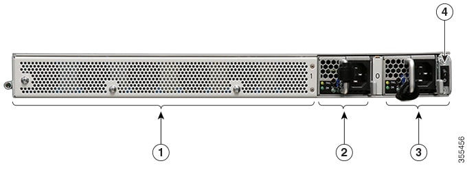
Rear Panel View
The following figure shows the rear of the Cisco C9800-40-K9 Wireless Controller.
|
1 |
Fans |
|
2 |
Power supply (PEM 1) |
|
3 |
Power supply (PEM 0) |
|
4 |
Power/standby switch |
|
Power Supply Condition |
Green (OK) LED Status |
Amber (FAIL) LED Status |
|---|---|---|
|
No AC power to all power supplies |
OFF |
OFF |
|
Power Supply Failure (includes over voltage, over current, over temperature and fan failure) |
OFF |
Red for Power Supply Failure Amber for Fan Failure |
|
Power Supply Warning events where the power supply continues to operate (high temperature, high power and slow fan) |
OFF |
1Hz Blinking |
|
AC Present/3.3VSB on (PSU OFF) |
1Hz Blinking |
OFF |
|
Power Supply ON and OK |
ON |
OFF |
Fans
The chassis has a front-to-rear airflow. Six internal fans draw cooling air into the chassis and across internal components to maintain an acceptable operating temperature. The fans are numbered from 0 to 5, right to left. The system is designed to operate indefinitely even if one of the fans fail. To reduce noise and power and increase fan lifetime, the speed of fans is automatically adjusted based on chassis inlet temperature. In the event of a single fan failure, all remaining fans will be increased to 100% fan speed account for the failed fan. However, multiple fan failures may result in over temperature and shut down.
Power Supply
Two power supplies (AC) are accessed from the rear of the controller and are hot-swappable. The Cisco C9800-40-K9 Wireless Controller supports AC power supply. The modular chassis configurations support the installation of two power supplies for redundancy. When an external power supply fails or is removed, the other power supply provides power requirements for the chassis. This allows you to hot-swap the power supply without impacting the functionality of the controller.
Power Supply LEDs
The following table describes the power supply LEDs.
|
Power Supply Condition |
Green (OK) LED Status |
Amber (FAIL) LED |
|---|---|---|
|
No AC power to all power supplies |
OFF |
OFF |
|
Power Supply Failure (includes over voltage, over current, over temperature and fan failure) |
OFF |
ON |
|
Power Supply Warning events where the power supply continues to operate (high temperature, high power and slow fan) |
OFF |
1 Hz Blinking |
|
Power Supply Condition |
Green (OK) LED Status |
Amber (FAIL) LED |
|---|---|---|
|
AC Present/3.3VSB on (PSU OFF) |
1Hz Blinking |
OFF |
|
Power Supply ON and OK |
ON |
OFF |
Power Supply Fans
The fans in the power supply module are used for cooling the power supply module itself while system-level cooling is provided by fans within the chassis. The power supplies do not depend on the system-level fans for cooling. Fan failure is determined by fan-rotation sensors.
Note |
|
Field Replaceable Units
Cisco C9800-40-K9 Wireless Controller shall have a minimal amount of separate orderable items, including all of the following:
-
AC Power Supplies
-
Rack mount bracket kit
Cisco Catalyst 9800 Wireless Controller Series: C9800-80-K9

The Cisco C9800-80-K9 Wireless Controller is a 100G wireless controller that occupies two rack unit space and supports a pluggable Module slot, and eight built-in 10GE/1GE interfaces.
Front Panel View
Cisco C9800-80-K9 Wireless Controller supports several LED indicators, and ports on the front panel. The front panel includes the following ports and LEDs.

|
S.No. |
Descriptions |
|---|---|
|
1 |
Power supply (PEM 0) |
|
2 |
Power supply (PEM 1) |
|
3 |
Power (PWR) switch |
|
4 |
PWR— Power LED |
|
5 |
SYS—System LED |
|
6 |
ALM—Alarm LED |
|
7 |
HA—High-Availability LED |
|
8 |
SP—RJ-45 10/100/1000 management Ethernet port |
|
9 |
RP— RJ-45 10/100/1000 redundancy Ethernet port |
|
10 |
RP— 1-GE SFP port(The only supported SFPs on RP port are : GLC-SX-MMD GLC-LH-SMD) |
|
11 |
USB ports 0 and 1 |
|
12 |
Bay 0—BUILT-IN-6x10GE/2x1GE or 10GE |
|
13 |
CON—RJ-45 compatible console port |
|
14 |
LINK—RJ-45 connector LED |
|
15 |
CON— Mini USB console port |
|
16 |
SSD— SSD activity LED |
|
17 |
SSD Access |
|
18 |
Bay 1 or Hot-Swap pluggable module |
Built-In SFP and SFP+ Ports
The following figure shows the port numbering for the built-in ports.

|
S.No |
Description |
|---|---|
|
1 |
Bay 0—The ports in Bay 0 use 1GE or 10GE SFP+ transceivers and are labeled TE0 - TE7. |
|
2 |
Bay 1—The ports in Bay 1 use 10GE SFP+ transceivers. BAY 1 supports.
|
The port Link and Status LEDs behave as follows:
|
Function |
Color or State |
Description |
|---|---|---|
|
A/L |
Green |
Port is enabled and the link is up. |
|
(Active/Link) |
Amber |
Port is enabled and the link is down. |
|
Off |
Port is not enabled. |
|
|
Status |
Green |
Module is ready and operational. |
|
Amber |
Module power is on and good, and the Module is being configured. |
|
|
Off |
Module power is off. |
C9800 Modules
-
C9800-18X1GE
Eighteen 1GE-ports that support small form-factor pluggable (SFP) optical transceivers to provide network connectivity. Ports are numbered 0 – 17
-
C9800-10X10GE
Ten 10GE-ports that support small form-factor pluggable (SFP+) optical transceivers to provide network connectivity. Ports are numbered 0 – 9.
-
C9800-2X40GE

-
C9800-1X40GE
-
C9800-1X100GE

Module LEDs
A module has two types of LEDs: an A/L (Active/Link) LED for each port on the Module, and a STATUS LED, as shown in the following table.
|
Function |
Color or State |
Description |
|---|---|---|
|
A/L (Active/Link) |
Green |
Port is enabled and the link is up. |
|
Amber |
Port is enabled and the link is down. |
|
|
Off |
Port is not enabled. |
|
|
Status |
Green |
Module is ready and operational. |
|
Amber |
Module power is on and good, and the Module is being configured. |
|
|
Off |
Module power is off. |
Supported SFP and SFP+
SFP
-
GLC-BX-D
-
GLC-BX-U
-
GLC-LH-SMD
-
GLC-SX-MMD
-
GLC-ZX-SMD
-
GLC-TE
Note |
|
SFP+
-
SFP-10G-SR
-
SFP-10G-SR-X
-
SFP-10G-LR
-
SFP-10G-LRM
-
SFP-10G-LR-X
-
SFP-10G-ER
-
SFP-10G-ZR
-
SFP-H10GB-ACU7M
-
SFP-H10GB-ACU10M
-
DWDM-SFP10G-30.33 –DWDM-SFP10G-61.41
Online Insertion and Removal (OIR)
We allow all ports to be independently configured as 1G ports or 10G ports and all SFP/SFP+(s) can be OIR'ed.
Management LEDs and Behavior
The following figure shows LEDs on the front panel of the Cisco C9800-80-K9 Wireless Controller.

The behaviour of the LEDs is as defined in the table below:
|
No |
LED Label |
Description |
LED Color |
Behavior |
||
|---|---|---|---|---|---|---|
|
1 |
PWR |
Power |
Green |
If all the power rails are based on the specification. |
||
|
2 |
SYS |
System |
On |
Remains ON during IOS boot complete. |
||
|
Blinking Green |
Remains blinking when IOS booting is in progress. |
|||||
|
Amber |
Remains ON during system crash. |
|||||
|
Blinking Amber |
Remains blinking during secure boot failure |
|||||
|
Off |
Remains OFF during ROMMON boot. |
|||||
|
3 |
ALM |
Alarm |
Green |
Remains ON during ROMMON boot complete. |
||
|
Blinking Green |
Remains blinking when system upgrade is in progress. |
|||||
|
Amber |
Remains ON during ROMMON and SYSTEM boot ups. |
|||||
|
Blinking Amber |
Remains blinking during temperature error and secure boot failure. |
|||||
|
Red |
Indicates that the system detects critical warnings.
|
|||||
|
Off |
Normal operation. |
|||||
|
4 |
HA |
High Availability |
Green |
Remains ON when HA is active. |
||
|
Blinking Green |
Remains blinking when HA Standby Hot.(Future) |
|||||
|
Amber |
Blinks slowly when booted or HA Standby Cold. (Future) |
|||||
|
Blinks Fast |
Blinks fast during HA maintenance. (Future) |
|||||
|
5 |
EN |
USB console enabled |
Green |
Indicates that the mini USB connector is used as the console. |
||
|
6 |
SSD |
SSD Activity |
Green |
Remains ON during the SSD activity. |
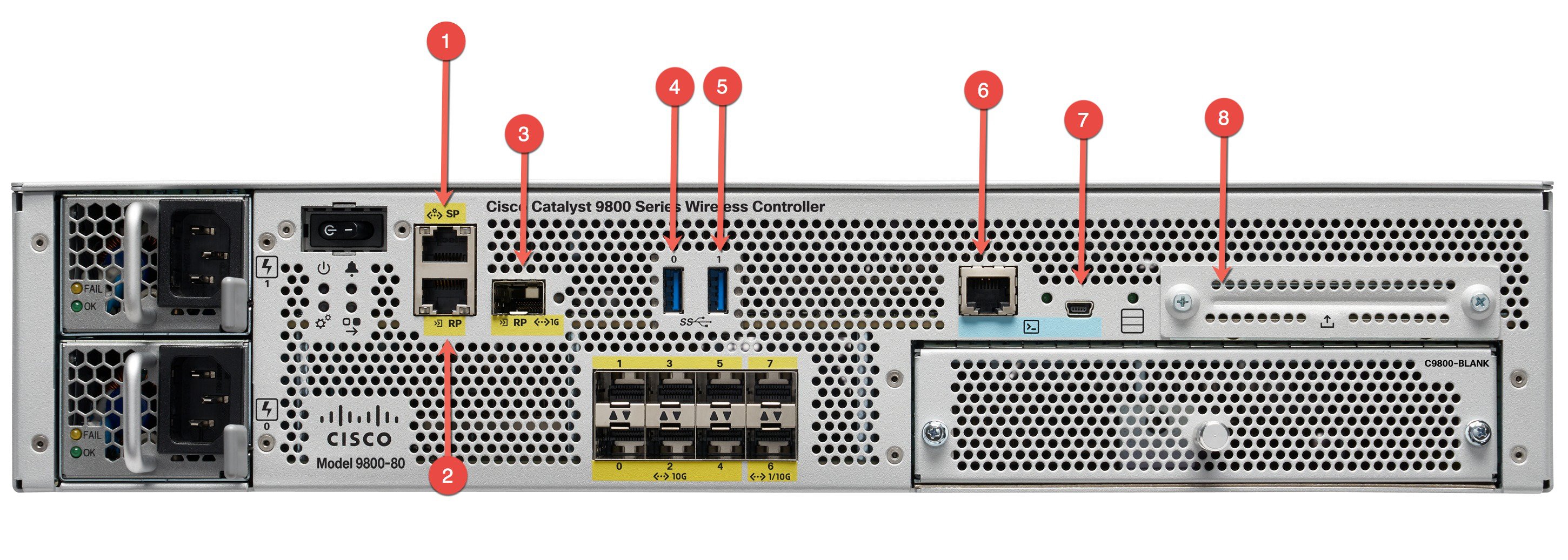
External Interfaces
|
S.No. |
Description |
|---|---|
|
1 |
MGMT— RJ-45 10/100/1000 management Ethernet port. |
|
2 |
RDCY— RJ-45 10/100/1000 redundancy Ethernet port. |
|
3 |
RDCY— 10GE SFP+ port. |
|
4 |
USB port 0 |
|
5 |
USB port 1 |
|
6 |
CON— RJ-45 compatible console port. |
|
7 |
CON— Mini USB connector console port. |
|
8 |
SSD Access |
Detail on Redundancy Ports
If both the Redundancy Ports are connected,
-
SFP Gigabit Ethernet port takes precedence if they are connected at same time.
-
HA between these two links is not supported.
-
Only Cisco supported SFPs (GLC-LH-SMD and GLC-SX-MMD) are supported for RP port.
-
When HA link is up via RJ-45, SFPs on HA port should not be inserted even if there is no link between them. As it is a physical level detection, this would cause the HA to go down as precedence is given to SFP.
Power Supply
-
The Cisco 9800 Wireless Controller support AC or DC power supply options. The modular chassis configurations support the installation of two power supplies for redundancy. When an external power supply fails or is removed, the other power supply provides power requirements for the chassis. This allows you to hot-swap the power supply without impacting the functionality of the controller.
-
A controller can support two AC or DC power supplies. Do not install mixed AC and DC power supply units in the same chassis.
-
The power supplies are used in a 1 + 1 redundant configuration. There is no input switch on the faceplate of the power supplies. A power supply is switched from Standby to On by way of a system chassis power switch.
Power Supply LEDs
The following table describes the power supply LEDs.
|
Power Supply Condition |
Green (OK) LED Status |
Amber (FAIL) LED Status |
|---|---|---|
|
No AC power to all power supplies |
OFF |
OFF |
|
Power Supply Failure (includes over voltage, over current, over temperature and fan failure) |
OFF |
Red for Power Supply Failure, Amber for Fan Failure |
|
Power Supply Warning events where the power supply continues to operate (high temperature, high power and slow fan) |
OFF |
1Hz Blinking |
|
AC Present/3.3VSB on (PSU OFF) |
1Hz Blinking |
OFF |
|
Power Supply ON and OK |
ON |
OFF |
Power Supply Fans
The fans in the power supply module are used for cooling the power supply module itself while system-level cooling is provided by fans within the chassis. The power supplies do not depend on the system-level fans for cooling. Fan failure is determined by fan-rotation sensors.
Rear Panel View
The following figure shows the rear of the Cisco C9800-80-K9 Wireless Controller.

Fans
The chassis has a front-to-rear airflow. Four internal fans draw cooling air in through the front of the chassis and across internal components to maintain an acceptable operating temperature. The fans are located at the rear of the chassis. The fans are numbered from 0 to 3, right to left.
The power supplies used in Cisco 9580 Wireless Controller are different and they should not be mixed or swapped. The size and structural dimensions are the same, therefore they both look alike. It would be hazardous, if you accidently inserted the wrong power supply into the PEM slot.
Field Replaceable Units
Cisco C9800-80-K9 Wireless Controller shall have a minimal amount of separate orderable items, including all of the following:
-
AC Power Supplies
-
Rack mount bracket kit
 Feedback