Context Aware Planning and Verification
Available Languages
Table Of Contents
Context Aware Planning and Verification
Planning for Data, Voice, and Location Deployment
Creating and Applying Calibration Models
Inspecting Location Readiness and Quality
Inspecting Location Readiness Using Access Point Data
Inspecting Location Quality Using Calibration Data
Using the Accuracy Tool to Conduct Accuracy Testing
Using Scheduled Accuracy Testing to Verify Accuracy of Current Location
Using On-demand Accuracy Testing to Test Location Accuracy
Using Chokepoints to Enhance Tag Location Reporting
Adding Chokepoints to the Cisco WCS
Removing Chokepoints from the WCS Database and Map
Using Location Sensors to Enhance Tag Location Reporting
Adding Location Sensors to Cisco WCS and Maps
Removing Location Sensors from Cisco WCS and Maps
Downloading Software for Location Sensors
Using Location Optimized Monitor Mode to Enhance Tag Location Reporting
Defining Inclusion and Exclusion Regions on a Floor
Defining an Inclusion Region on a Floor
Defining an Exclusion Region on a Floor
Defining a Rail Line on a Floor
Enabling Location Presence on a Mobility Services Engine
Modifying Context Aware Software Parameters
Modifying Filtering Parameters
Editing Advanced Location Parameters
Context Aware Planning and Verification
This chapter describes a number of tools and configurations that can be used to enhance the location accuracy of elements (clients, tags, rogue clients, and rogue access points) within an indoor or outdoor area.
Context Aware Software (CAS) installed on a mobility services engine retrieves location as well as other contextual information such as temperature and asset availability about a client or tag (Cisco CX version 1 or later) from access points.

Note
Non-Cisco CX tags are not tracked or mapped by Cisco WCS.
Note
This chapter contains the following sections:
•
•
•
•
•
•
•
•
•
•
•
Note
•
Planning for Data, Voice, and Location Deployment
You can calculate the recommended number and location of access points based on whether data and/or voice traffic and/or location will be active.
To calculate recommended number and placement of access points for a given deployment, follow these steps:
Step 1
Step 2
A map appears showing placement of all installed elements (access points, clients, tags) and their relative signal strength.
Step 3
A color-coded map summarizing contributing access points appears.
Step 4
Step 5
Note
Step 6
The recommended number of access points given the services requested appears.
Note
Note
Step 7
Note
Creating and Applying Calibration Models
If the provided RF models do not sufficiently characterize the floor layout, you can create a calibration model that is applied to the floor and better represents the attenuation characteristics of that floor. In environments in which many floors share common attenuation characteristics (such as in a library), one calibration model can be created and then applied to floors with the same physical layout and same deployment.
You can collect data for a calibration using one of two methods:
•
•
Note
Note
Use a laptop or other wireless device to open a browser to Cisco WCS and perform the calibration process.
To create and apply calibration models, follow these steps:
Step 1
Step 2
Step 3
Step 4
Step 5
Step 6
Figure 7-1 Starting to Calibrate
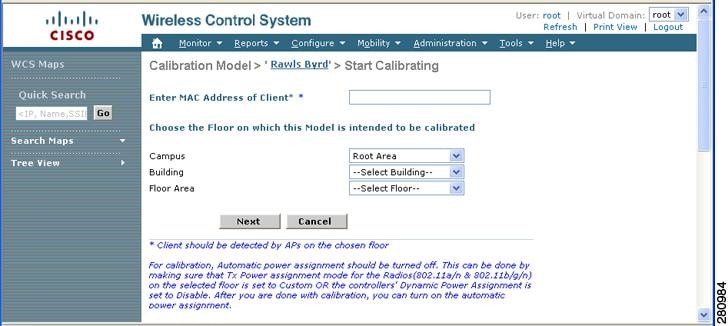
Step 7
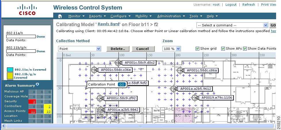
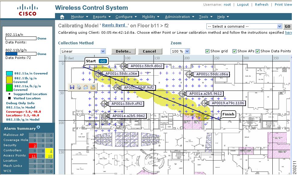
Using these locations as guidelines, you can perform either a point or linear collection of data by appropriate placement of either the Calibration Point pop-up (point) or the Start and Finish pop-ups (linear) that display on the map when the respective options are displayed. Figure 7-2 shows the starting window for a point calibration.
Figure 7-2 Positioning Calibration Points
a.
1.
2.
Note
3.
Note
Note
4.
Note
b.
1.
2.
3.
4.
Note
5.
Note
Figure 7-3 Linear Data Collection
Note
6.
Note
Step 8
Step 9
Step 10
Step 11
Step 12
Note
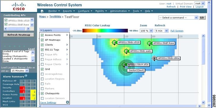
Inspecting Location Readiness and Quality
You can configure Cisco WCS to verify the ability of the existing access point deployment to estimate the true location of a client, rogue client, rogue access point, or tag within 10 meters at least 90% of the time. The location readiness calculation is based on the number and placement of access points.
You can also check the location quality and the ability of a given location to meet the location specification (10 m, 90%) based on data points gathered during a physical inspection and calibration.
Inspecting Location Readiness Using Access Point Data
To inspect location readiness using access point data, follow these steps:
Step 1
Step 2
A map displays showing placement of all installed elements (access points, clients, tags) and their relative signal strength.
Note
Step 3
A color-coded map appears showing those areas that do (Yes) and do not (No) meet the 10 meter, 90% location specification.
Inspecting Location Quality Using Calibration Data
After completing a calibration model based on data points generated during a physical tour of the area, you can inspect the location quality of the access points. To inspect location quality based on calibration, follow these steps:
Step 1
Step 2
A list of calibration models appears.
Step 3
Details on the calibration including date of last calibration, number of data points by signal type (802.11a, 802.11 b/g) used in the calibration, location, and coverage are displayed.
Step 4
A color-coded map noting percentage of location errors appears.
Note
Verifying Location Accuracy
By checking for location accuracy, you are checking the ability of the existing access point deployment to estimate the true location of an element within 10 meters at least 90% of the time.
You can analyze the location accuracy of non-rogue and rogue clients and asset tags by using the Accuracy Tool.
The Accuracy Tool enables you to run either a scheduled or on-demand location accuracy test. Both tests are configured and executed through a single window.
Using the Accuracy Tool to Conduct Accuracy Testing
There are two methods of conducting location accuracy testing:
•
•
Both are configured and executed through a single window.
Note
Follow these steps to enable the advanced debug option in Cisco WCS.
Step 1
Step 2
Step 3
Note
You can now run location accuracy tests on the mobility services engine using the Accuracy Tool.
Using Scheduled Accuracy Testing to Verify Accuracy of Current Location
To configure a scheduled accuracy test, do the following:
Step 1
Step 2
Step 3
Step 4
Step 5
Step 6
Step 7
Step 8
Note
Step 9
Note
Step 10
Step 11
When you check a MAC address check box, two icons which overlay each other appear on the map.
One icon represents the actual location and the other the reported location.
Note
Step 12
Step 13
Step 14
Note
Step 15
Step 16
The Scheduled Location Accuracy Report includes the following information:
•
•
•
•
•
Using On-demand Accuracy Testing to Test Location Accuracy
An On demand Accuracy Test is run when elements are associated but not pre-positioned. On demand testing allows you to test the location accuracy of clients and tags at a number of different locations. It is generally used to test the location accuracy for a small number of clients and tags.
To run an On-demand Accuracy Test, do the following:
Step 1
Step 2
Step 3
Step 4
Step 5
Step 6
Step 7
Step 8
Step 9
Step 10
Step 11
Step 12
Step 13
Step 14
Step 15
Step 16
The On-demand Accuracy Report includes the following information:
•
•
•
Note
•
•
•
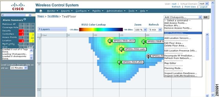
Using Chokepoints to Enhance Tag Location Reporting
Installing chokepoints provides enhanced location information for active RFID tags. When an active Cisco CX version 1 compliant RFID tag enters the range of a chokepoint, it is stimulated by the chokepoint. The MAC address of this chokepoint is then included in the next beacon sent by the stimulated tag. All access points that detect this tag beacon then forward the information to the controller and location appliance.
Using chokepoints in conjunction with active Cisco CX compliant tags provides immediate location information on a tag and its asset. When a Cisco CX tag moves out of the range of a chokepoint, its subsequent beacon frames do not contain any identifying chokepoint information. Location determination of the tag defaults to the standard calculation methods based on RSSIs reported by access point associated with the tag.
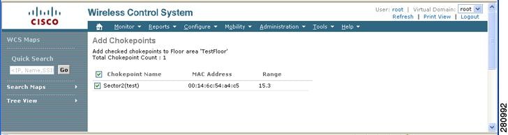
Adding Chokepoints to the Cisco WCS
Chokepoints are installed and configured as recommended by the chokepoint vendor. When the chokepoint is installed and operational, you can add the chokepoint to the location database and positioned on a Cisco WCS map.
Note
To add a chokepoint to Cisco WCS, follow these steps:
Step 1
The All Chokepoints summary window appears.
Step 2
The Add Chokepoint entry screen appears.
Figure 7-4 Add Chokepoint Window

Step 3
Note
Step 4
Note
Step 5
The All Chokepoints summary window appears with the new chokepoint entry listed (Figure 7-5).
Figure 7-5 All Chokepoints Summary Window

Note
Step 6
Figure 7-6 Monitor > Maps Window
Step 7
Figure 7-7 Selected Floor Map
Step 8
The Add Chokepoints summary window appears (Figure 7-8).
Note
Figure 7-8 Add Chokepoints Summary Window
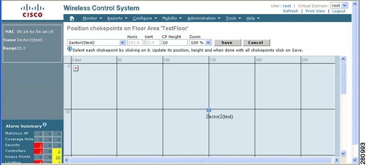
Step 9
A map appears with a chokepoint icon located in the top-left hand corner. You can now place the chokepoint on the map.
Step 10
Figure 7-9 Chokepoint Icon is Positioned on the Floor Map
Note
Step 11
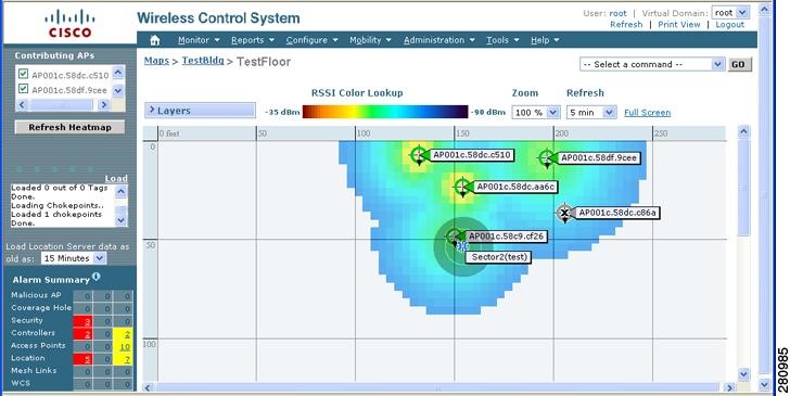
You are returned to the floor map and the added chokepoint appears on the map (Figure 7-10).
Note
Figure 7-10 New Chokepoint Displayed on Floor Map
Note
Note
Step 12
The chokepoint appears on the map (Figure 7-11).
Figure 7-11 Chokepoints Displayed on Map
Step 13
Note
Removing Chokepoints from the WCS Database and Map
You can remove one or multiple chokepoints at a time.
Follow these steps to delete a chokepoint.
Step 1
Step 2
Step 3
Figure 7-12 Removing a Chokepoint
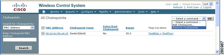
Step 4
You are returned to the All Chokepoints window. A message confirming deletion of the chokepoint appears. The deleted chokepoint(s) is no longer listed in the window.
Using Location Sensors to Enhance Tag Location Reporting
The location sensor (also known as a Wi-Fi TDOA location receiver) is an external system designed to receive signals transmitted from a tagged, tracked asset. These signals are then forwarded to the mobility services engine to aid in the location calculation of the asset. Location sensors use the method of Time Difference of Arrival (TDOA) to calculate tag location. This method uses data from a minimum of three location sensors to generate a tagged asset's location.
Note
•
Before using a location sensor within the Cisco Unified Wireless Network, you must:
1.
Refer to Chapter 2, "Adding and Deleting Systems" for details on adding a mobility services engine.
2.
Refer to "Adding Location Sensors to Cisco WCS and Maps" section for details on adding the location sensor to Cisco WCS.
3.
Refer to "Downloading Software for Location Sensors" section for details on downloading the software.
4.
Refer to Chapter 3, "Synchronizing Mobility Services Engines" for details on synchronization.
5.
Note
Note
Adding Location Sensors to Cisco WCS and Maps
After the location sensor is installed and configured by the AeroScout System Manager and the partner software is downloaded on the mobility services engine, you are ready to add the location sensor to the mobility services engine database and position it on a Cisco WCS map.
After adding location sensors to Cisco WCS maps, you continue to make configuration changes to the location sensor using the AeroScout System Manager application rather than Cisco WCS.
Note
To add a location sensor to the Cisco WCS database and appropriate map, follow these steps:
Step 1
Step 2
Step 3
Step 4
Note
Step 5
Step 6
Step 7
The Add Location Sensors summary window appears.
Note
Step 8
A map appears with a location sensor icon located in the top-left hand corner. You are now ready to place the location sensor on the map.
Step 9
Note
Step 10
You are returned to the floor heat map and the added location sensor appears on the map.
Note
Step 11
Step 12
Note
Figure 7-13 Location Sensor Enabled on Layers Menu for Map Display

Step 13
Note
Step 14
Refer to the "Downloading Software for Location Sensors" section for details.
Removing Location Sensors from Cisco WCS and Maps
You can remove one or multiple location sensors at a time. <ADD the maps section; if you remove from MP it comes back unassigned but still in database; approach below removes from WCS database.>
To delete a location sensor, follow these steps.
Step 1
Step 2
Step 3
Step 4
You are returned to the All Location Sensors window. A message confirming deletion of the location sensor appears. The deleted location sensor is no longer listed in the window.
Downloading Software for Location Sensors
Note
To download software for the location sensor to the mobility services engine, follow these steps:
Step 1
Step 2
Step 3
Step 4
a.
Cisco WCS downloads the binary images listed in the drop-down menu into the FTP server directory you specified during Cisco WCS installation.
b.
Step 5
Step 6
Note
Note
Once the partner engine software is installed on the mobility services engine, two additional options, Logs and Status, are available on the Partner Engine Menu. Refer to Chapter 9, "Performing Maintenance Operations" for details.
Note
Using Location Optimized Monitor Mode to Enhance Tag Location Reporting
To optimize monitoring and location calculation of tags, you can enable LOMM on up to four channels within the 2.4GHz band (802.11b/g radio) of an access point. This allows you to focus channel scans only on those channels on which tags are usually programmed to operate (such as channels 1, 6, and 11).
After enabling Monitor Mode at the access point level, you must then enable LOMM and assign monitoring channels on the 802.11 b/g radio of the access point.
Note
Follow the steps below to set enable LOMM and assign monitoring channels on the access point radio.
Step 1
Step 2
Step 3
Step 4
Step 5
Note
Step 6
Step 7
Step 8
The AP Mode display as Monitor/LOMM on the Monitor > Access Points window.
Defining Inclusion and Exclusion Regions on a Floor
To further refine location calculations on a floor, you can define the areas that are included (inclusion areas) in the calculations and those areas that are not included (exclusion areas).
For example, you might want to exclude areas such as an atrium or stairwell within a building but include a work area (such as cubicles, labs, or manufacturing floors).
Note
Guidelines
Inclusion and exclusion areas can be any polygon shape and must have at least three points.
You can only define one inclusion region on a floor. By default, an inclusion region is defined for each floor when it is added to Cisco WCS. The inclusion region is indicated by a solid aqua line, and generally outlines the region.
You can define multiple exclusion regions on a floor.
Newly defined inclusion and exclusion regions appear on heatmaps only after the mobility services engine recalculates location.
Defining an Inclusion Region on a Floor
Follow the steps below to define an inclusion area.
Step 1
Step 2
Step 3
Step 4
Note
Figure 7-14 Map Editor Window

Step 5
Step 6
Step 7
Step 8
Step 9
Note
Step 10
Step 11
Step 12
Step 13
Step 14
Check the Sync. Status column to ensure that the synchronization is successful (two green arrows).
Note
Defining an Exclusion Region on a Floor
To further refine location calculations on a floor, you can define areas that are excluded (exclusion areas) in the calculations.
For example, you might want to exclude areas such as an atrium or stairwell within a building.
As a rule, exclusion areas are generally defined within the borders of an inclusion area.
Follow the steps below to define an exclusion area.
Step 1
Step 2
Step 3
Step 4
Step 5
Step 6
Step 7
Step 8
Step 9
Figure 7-15 Defining Exclusion Areas on Floor Map
Step 10
Note
Step 11
Step 12
Step 13
Step 14
Step 15
Check the Sync. Status column to ensure that the synchronization is successful (two green arrows).
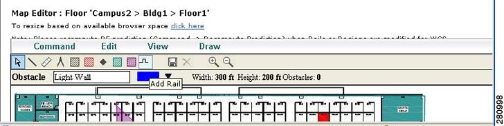
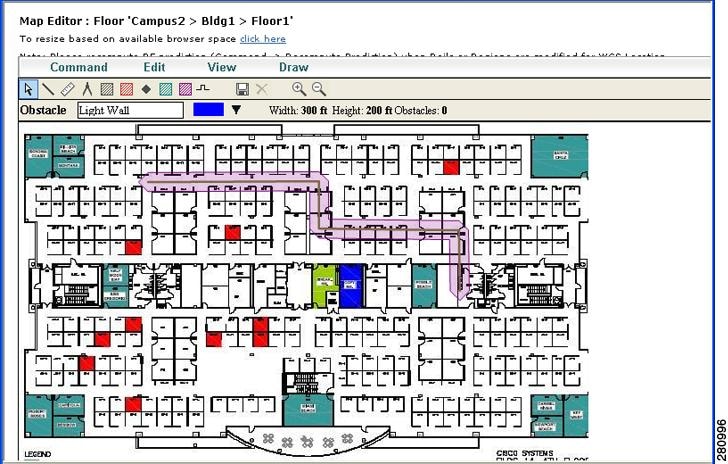
Defining a Rail Line on a Floor
You can define a rail line on a floor that represents a conveyor belt. Additionally, you can define an area around the rail area known as the snap-width to further assist location calculations. This represents the area in which you expect clients to appear. Any client located within the snap-width area is plotted on the rail line (majority) or just outside of the snap-width area (minority).
Note
The snap-width area is defined in feet or meters (user-defined) and represents the distance that is monitored on either side (east and west or north and south) of the rail.
Follow the steps below to define a rail with a floor.
Step 1
Step 2
Step 3
Step 4
Figure 7-16 Rail Icon on Map Editor Tool Bar
Step 5
Note
Step 6
Step 7
Figure 7-17 Rail Line
Note
Step 8
Step 9
Step 10
Step 11
Step 12
Check the Sync. Status column to ensure that the synchronization is successful (two green arrows).
Enabling Location Presence on a Mobility Services Engine
You can enable location presence by mobility services engine to provide expanded Civic (city, state, postal code, country) and GEO (longitude, latitude) location information beyond the Cisco default setting (campus, building, floor, and X, Y coordinates). This information can then be requested by clients on a demand basis for use by location-based services and applications.
Location Presence can be configured when a new Campus, Building, Floor or Outdoor Area is being added or configured at a later date.
Note
Follow these steps to enable and configure location presence on a mobility services engine. Once enabled, the mobility services engine is capable of providing any requesting Cisco CX v5 client its location.
Note
Step 1
Step 2
Step 3
Step 4
a.
–
b.
–
c.
–
Step 5
a.
b.
c.
Step 6
Step 7
Step 8
Step 9
Modifying Context Aware Software Parameters
You can modify Context Aware Software properties as to the type and number of clients or tags that are tracked and whether or not locations are calculated for those clients or tags.
You can also modify parameters that affect the location calculation of clients and tags such as Receiver Signal Strength Indicator (RSSI) measurements.
Note
Modifying Tracking Parameters
The mobility services engine can track up to18,000 clients and up to18,000 tags (with the proper license purchase). Updates on the locations of elements being tracked are provided to the mobility services engine from the Cisco wireless LAN controller.
Only those elements designated for tracking by the controller are viewable in Cisco WCS maps, queries and reports. No events and alarms are collected for non-tracked elements and none are used in calculating the 18,000 element limit for clients or tags.
You can modify the following tracking parameters using Cisco WCS:
•
•
For example, given a client license of 12,000 trackable units, you could set a limit to track only 8,000 client stations (leaving 4,000 units available to track rogue clients and rogue access points). Once the tracking limit is met for a given element, the number of elements not being tracked is summarized on the Tracking Parameters page.
•
To configure tracking parameters for a mobility services engine, follow these steps:
Step 1
Step 2
Step 3
Step 4
:
Step 5
Modifying Filtering Parameters
In Cisco WCS, you can limit the number of asset tags, clients, and rogue clients and access points whose location is tracked by filtering on:
•
Specific MAC addresses can be entered and labeled as allowed or disallowed from location tracking. You can import a file with the MAC addresses that are to be allowed or disallowed, or you can enter them individually from the WCS GUI window.
The format for entering MAC addresses is xx:xx:xx:xx:xx:xx. If a file of MAC addresses is imported, the file must follow a specific format as noted below:
–
–
–
Note
EXAMPLE file listing:
[Allowed]
00:11:22:33:*
22:cd:34:ae:56:45
02:23:23:34:*
[Disallowed]
00:10:*
ae:bc:de:ea:45:23•
Probing clients are clients that are associated to another controller but whose probing activity causes them to be seen by another controller and counted as an element by the "probed" controller as well as its primary controller.
To configure filtering parameters for a mobility services engine, follow these steps:
Step 1
Step 2
Step 3
Step 4
Step 5
Editing Advanced Location Parameters
You can use Cisco WCS to modify parameters that affect location calculations such as Receiver Signal Strength Indicator (RSSI) measurements for clients.
You can also apply varying smoothing rates to manage location movement of a client.
Note
To configure advanced location parameters, follow these steps:
Step 1
Step 2
Step 3
Step 4
Table 7-3 Advanced Location Parameters
Calculation time
Check the corresponding check box to enable the calculation of the time required to compute location.
Note

Caution
OW Location
Check the corresponding check box to enable Outer Wall (OW) calculation as part of location calculation.
Note
Relative discard RSSI time
Enter the number of minutes since the most recent RSSI sample after which RSSI measurement should be considered discarded. For example, if you set this parameter to 3 minutes and the mobility services engine receives two samples at 10 and 12 minutes, it keeps both samples. An additional sample received at 15 minutes is discarded. Default value is 3. Allowed values range from 0 to 99999. A value of less than 3 is not recommended.
Note
Absolute discard RSSI time
Enter the number of minutes after which RSSI measurement should be considered stale and discarded, regardless of the most recent sample. Default value is 60. Allowed values range from 0 to 99999. A value of less than 60 is not recommended.
Note
RSSI Cutoff
Enter the RSSI cutoff value, in decibels (dBs) with respect to one (1) mW (dBm), above which the mobility services engine will always use the access point measurement. Default value is -75.
Note
Note
Caution
Smooth Location Positions
Smoothing compares an element's prior location to its most recent reported location by applying a weighted average calculation to determine its current location. The specific weighted average calculation employed is tied to the given smoothing option selected. Default value is More Smoothing.
Options:
•
•
•
•
•
Note
Chokepoint Usage
Check the Enable check box to enable tracking of Cisco compatible tags by chokepoints.
Note
Use Chokepoints for Interfloor conflicts
Perimeter chokepoints or weighted location readings can be selected to determine the location of Cisco compatible tags.
Options:
•
•
•
Note
Chokepoint Out of Range Timeout
When a Cisco compatible tag leaves a chokepoint range, the timeout period entered is the period that passes before RSSI values are again used for determining location.
Note
Allow Civic Address updates from Switches
Check the enable check box to receive civic address updates from the controller. When enabled, the civic address parameter provides city, state, postal code and country specifics for the mobility services engine. This capability is in addition to the Cisco default settings of campus, building, floor, and X, Y coordinates. This information can then be requested by clients on demand for use by location-based services and applications.
Note
Step 5
 Feedback