Cisco IW-PWRADPT-MFIT Series Power Supply Installation Guide
This document describes the Cisco IW-PWRADPT-MFIT series Power Supply (referred to as the power supply in this document) and provides instructions for mounting the unit.
Product Overview
The Cisco power supply models IW-PWRADPT-MFIT4P= and IW-PWRADPT-MFITIN= are an outdoor single-phase AC/DC, 60-Watt output external wide temperature range power supply with the DC voltage output of 48V. The power supply operates between 90VAC to 264 VAC and 135VDC to 370VDC.
The IW-PWRADPT-MFITIN= power adapter is designed for the Indian market and meets the Indian regulatory compliance requirements.
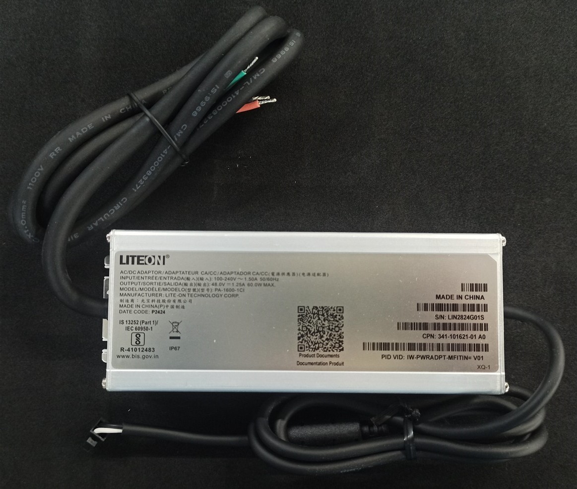
Unpacking the Power Adapter
The following items are shipped with the power adapter:
|
Power adapter |
|
AC power cord, integrated into power adapter, unterminated |
|
DC power cord, integrated into power adapter, terminated with micro-fit connector |
|
Power adapter |
|
AC power cord, integrated into power adapter, unterminated |
|
DC power cord, integrated into power adapter, terminated with micro-fit connector |
|
8MM NYLON WASHER (4X) |
|
SST FLAT WASHER (4X) |
|
SST SPLIT LOCK WASHER (4X) |
|
6-32 NUT (4X) |
If any item is missing or damaged, contact your Cisco representative or reseller.
AC Cable Assembly
Connect the corresponding phase of wire of AC cable with power system.
|
Phase |
IW-PWRADPT-MFIT4P= Wire Color 
|
IW-PWRADPT-MFITIN= Wire Color 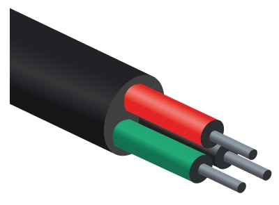
|
|---|---|---|
|
L |
Brown |
Red |
|
N |
Blue |
Black |
|
E |
Green/Yellow |
Green |
When connecting to AC plug, different types of plugs should be used in each country. The following table is for reference.
|
Plug Type |
Country |
Plug Type |
Country |
|---|---|---|---|

|
US, Taiwan, Japan, Canada, Mexico |

|
UK, Singapore |

|
European, Morocco |

|
Korea, Russia |

|
China, Australia, Argentina |

|
India, South Africa |
DC Cable Assembly
The power adapter is pre-terminated with a Molex Microfit 3.0 Receptacle with two contacts populated. The remaining positions are unused. The following table shows the pinouts. Output cable length shall be one meter +/- 5%.

Microfit 3.0 receptacle front view
|
Molex Microfit Pin |
Assignment |
|---|---|
|
Pin 1 |
Black ( - Negative Terminal) |
|
Pin 2 |
Not assigned |
|
Pin 3 |
White (+ Positive Terminal) |
|
Pin 4 |
Not assigned |
For DC cable asembly, insert the receptable into the header in system. The following picture is only for reference.

|
1 |
Receptacle Molex Microfit 3.0 430250400, crimp terminal,female, 430300040 |
2 |
Header/Plug: 4 Pin Microfit 3.0 compatible Plug |
Technical Specifications
This table lists specifications for the power supply:
|
Specification |
IW-PWRADPT-MFIT4P= |
IW-PWRADPT-MFITIN= |
|---|---|---|
|
Input-voltage range and frequency |
AC input: 100-240V, 50-60Hz (nominal) DC input: 35 to 370 VDC |
|
|
Output voltage and current |
48 VDC, 1.25A, 60 W Max |
|
|
Physical specification |
Dimensions (W x H x L): 46.5 mm x 62 mm x 171 mm Weight: 685g +/-30g |
|
|
Operating temperature |
-40°C to +65°C, still air condition including solar loading |
|
|
Non-operating temperature |
-40°C to +85°C |
|
|
Humidity |
Operating: 5% to 95%, condensing is allowed outside of adapter Non-operating: 5% to 95%, condensing is allowed outside of adapter IP67 Rated |
|
|
Thermal shock |
Operating thermal shock: -40°C to + 65°C at 0.5°C per minute Non-operating thermal shock: -40°C to +85°C, with change over time between 2 and 3 minutes |
|
|
Altitude |
Operating altitude: -500 to 17,000 feet from sea level Non-operating altitude:-1,000 to 30,000 feet from sea level |
|
|
Reliability |
MTBF: 300,000 hrs @ 40ºC |
|
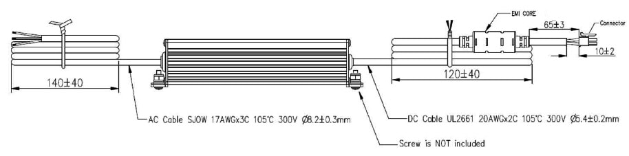
Mechanical Specifications
All measurements in the following figures are in mm.


Mounting Instructions
 Warning |
All IW-PWRADPT-MFIT4P= versions (before V02) did not have insulated mounting spacers. When mounting these power adapters, care should be exercised, and the chassis should be isolated from any conductive mounting surface. |
You can attach the power adapter to the IW9167EH access point on a pole using the mounting bracket AIR-ACCPMK3700= or AIR-ACCPMK3700-2=. For detailed information on mounting procedures, see Attaching a Power Adapter in Cisco Catalyst IW9167E Heavy Duty Access Point Hardware Installation Guide.
You can also mount the power adapter to most vertical or horizontal surfaces using the mounting tabs on the right and left of the unit. For details, see Mount Adapter using Screws and Mount Adapter using 6-32 Threaded Posts.
 Note |
The device must be connected to a grounded outlet. |
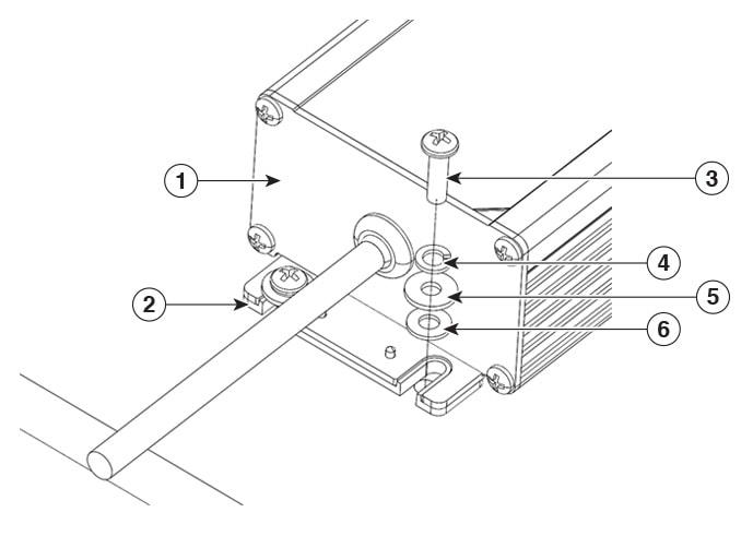
Mount Adapter using Screws
Follow these steps to mount the power adapter using screws to a vertical or horizontal surface using the mounting tabs.
|
1 |
Power Supply |
4 |
Split lock washer (SST) |
|
2 |
Insulator spacer integrated onto power adapter |
5 |
Flat washer (SST) |
|
3 |
6-32, M3.5 or equivalent sized hardware, Not Supplied |
6 |
Nylon insulating washer |
Procedure
|
Step 1 |
Using slots in Power Adapter or dimensions from detailed drawing, drill through holes or tapped holes depending on mounting surface type and hardware used to attach. The hardware must be able to support a 20 lb pull force. |
||
|
Step 2 |
Drill a hole at each marked location. |
||
|
Step 3 |
Assemble the washers onto the screw. Assemble the split lock washer, flat washer, and nylon insulating washer onto the screw as shown in Exploded View. The nylon insulating washer should rest againast the mounting flange on the power adapter.
|
Mount Adapter using 6-32 Threaded Posts
Follow these steps to mount the power adapter using 6-32 threaded posts to a vertical or horizontal surface using the mounting tabs.
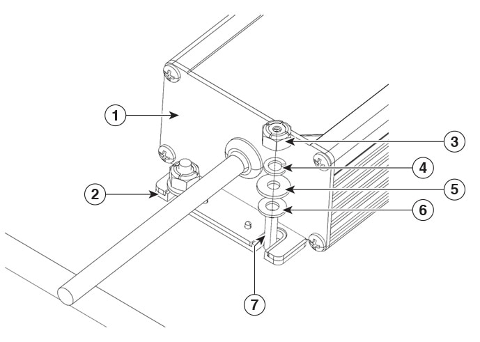
|
1 |
Power Supply |
5 |
Flat washer (SST) |
|
2 |
Insulator spacer integrated onto power adapter |
6 |
Nylon insulating washer |
|
3 |
6-32 Nut |
7 |
6-32UNC-2A threaded post |
|
4 |
Split lock washer (SST) |
Before you begin
Note |
You may skip steps 1-3 when installing the power adapter on the mounting bracket AIR-ACCPMK3700= or AIR-ACCPMK3700-2= as these posts are integrated into these brackets. |
Procedure
|
Step 1 |
Using the holes in the power adapter mounting tabs as a template, mark the locations on the surface where you will drill the holes for the 6-32 screw or threaded stand-off coming from back of mounting surface. |
||
|
Step 2 |
Drill a hole at each marked location. |
||
|
Step 3 |
Insert the #6-32 UNC-2A posts or screws from the underside of wall or surface through the mounting tabs holes. |
||
|
Step 4 |
Assemble the washers onto the post. Assemble the split lock washer, flat washer, and nylon insulating washer onto the post as shown in Exploded View. The nylon insulating washer should rest againast the mounting flange on the power adapter. Tighten the nut with 9-11 lb-in torque into the surface.
|
Regulatory Information
The following information is for FCC compliance of Class B devices:
The equipment described in this manual generates and may radiate radio-frequency energy. If it is not installed in accordance with Cisco’s installation instructions, it may cause interference with radio and television reception. This equipment has been tested and found to comply with the limits for a Class B digital device in accordance with the specifications in part 15 of the FCC rules. These specifications are designed to provide reasonable protection against such interference in a residential installation. However, there is no guarantee that interference will not occur in a particular installation.
Modifying the equipment without Cisco’s written authorization may result in the equipment no longer complying with FCC requirements for Class A or Class B digital devices. In that event, your right to use the equipment may be limited by FCC regulations, and you may be required to correct any interference to radio or television communications at your own expense.
You can determine whether your equipment is causing interference by turning it off. If the interference stops, it was probably caused by the Cisco equipment or one of its peripheral devices. If the equipment causes interference to radio or television reception, try to correct the interference by using one or more of the following measures:
-
Turn the television or radio antenna until the interference stops.
-
Move the equipment to one side or the other of the television or radio.
-
Move the equipment farther away from the television or radio.
-
Plug the equipment into an outlet that is on a different circuit from the television or radio. (That is, make certain the equipment and the television or radio are on circuits controlled by different circuit breakers or fuses.)
Modifications to this product not authorized by Cisco Systems, Inc. could void the FCC approval and negate your authority to operate the product.
 Feedback