Compliance to 3GPP Specifications

Feature Summary and Revision History

Summary Data

Table 1. Summary Data

Applicable Product(s) or Functional Area

AMF

Applicable Platform(s)

SMI

Feature Default Setting

Not Applicable

Related Documentation

Not Applicable

Revision History

Table 2. Revision History

Revision Details

Release

First introduced.

2021.04.0

Feature Description

The Access and Mobility Management Function (AMF) supports the 3GPP-released June-19 specifications on all the interfaces.

In the 5G network, the AMF offers services to the other AMF, PCF, NSSF, NRF, NEF, UDM, and AF via the Namf service-based interface (see 3GPP TS 23.501 and 3GPP TS 23.502).

The SMF, PCF, NRF, AUSF and UDM interfaces are currently supported from AMF. For more information, see http://www.3gpp.org/ftp/Specs/archive/29_series/29.518/29518-f00.zip.

The following reference diagram represents a high-level network containing AMF connected to other nodes.

Standards Compliance

Cisco AMF complies with the 3GPP standards. For more information, refer to Standards Compliance.

How it Works

This section describes how this feature works.

Call Flows

This section describes the key call flows of compliance to 3GPP specifications.

UE Registration

To enable UE tracking and reachability, a UE must register with the network to be authorized to receive services.

Initial Registration Request Call Flow

This section describes the Initial Registration Request call flow.

Figure 1. Initial Registration Request Call Flow
Table 3. Initial Registration Request Call Flow Description

Step

Description

1

An UE which wants to register itself with the 5G core sends a Registration-Request N1 message towards AMF with the following contents:

  • Registration type

  • SUCI or 5G-GUTI

  • Last visited TAI (if available)

  • Security parameters

  • Requested NSSAI

  • UE radio capability

  • UE MM core network capability

  • PDU session status

  • List of PDU sessions to be activated

  • Follow on request

If the subscriber is unknown, AMF allocates AMF-NGAP-id to the NGAP connection and subscriber data-store. The AMF-NGAP-id to AMF-Service is stored in etcd so that subsequent messages over the NGAP connection reach same AMF-Service. gNB selects an AMF and forwards the registration-request message to AMF.

2

If the identity received from the UE was either a SUCI, SUPI, or GUTI allocated by this AMF, the AMF authenticates the UE as presented in the authentication procedure.

3

If the AMF is configured to do EIR checks during registration, the AMF retrieves the PEI from the UE during security mode command procedure. It then checks the status of the equipment during registration procedure.

4

Depending on the status of the equipment from EIR, the AMF either rejects the registration or proceeds with the call. Actions to be taken when the status is grey listed is configurable on the call control policy currently active for the UE.

5

The AMF selects an UDM based on the PLMN information through NRF query or via static configuration and registers the UE with the UDM using Nudm_UECM_Registration.

6

The UDM stores the AMF identity and responds to the AMF request.

7

The AMF requests from the UDM the Access and Mobility Subscription, and SMF Selection Subscription Data using Nudm_SDM_Get and using multiple data set names. If integrity check passes and UDM subscription data already exit in UE context, AMF skips Steps 7 - 10.

8

The UDM responds to the request from the AMF. The AMF stores the subscription information.

9

The AMF subscribes to be notified using Nudm_SDM_Subscribe when the data requested is modified.

10

The UDM registers the AMF and responds to the AMF.

11

The AMF selects PCF based on PLMN-info and slice-info and performs a policy association establishment. PCF sends policy data to AMF with restrictions and other policies to be applied for the UE.

Note 

If the integrity check passes and PCF subscription data already exit in UE context, AMF skips this step.

12

The PCF responds to the AMF request along with AM-Policy configurations for the subscriber.

13

The AMF sends a Registration Accept message to the UE indicating that the Registration Request has been accepted. Registration Accept contains (registration area, mobility restrictions, PDU session status, allowed NSSAI, configured NSSAI for the serving PLMN, periodic registration update timer, emergency service support indicator, accepted DRX parameters).

14

If the AMF sends an Initial Context Setup Request, the gNB responds with an Initial Context Setup Response. This message could come after the message in Step 12.

15

The UE sends a Registration Complete message to the AMF to acknowledge that a new 5G-GUTI was assigned if a new 5G GUTI was included in the Registration Accept message.

16

If the UE did not include a follow-on indication in the request, the AMF releases the UE gNB context by sending a UE Context Release Command to the gNB

17

The gNB responds with a UE Context Release Complete message to the AMF.

Mobility Updating or Periodic Registration without AMF Change Call Flow

This section describes the Mobility Updating or Periodic Registration without AMF Change call flow.

Figure 2. Mobility Updating or Periodic Registration without AMF Change Call Flow
Table 4. Mobility Updating or Periodic Registration without AMF Change Call Flow Description

Step

Description

1

The UE triggers the Mobility Updating or Periodic Registration procedure under the following conditions:

  1. The Periodic Registration timer in the UE expires. The UE sets up the registration type as Periodic in this case, and the message arrives on the AMF as an Initial UE NGAP message.

  2. The UE is in idle state and moves to an area that is not currently part of its Tracking Area List. In this case, the UE sets the type to Mobility Updating, and the NGAP message is the Initial UE message.

  3. After or during handover, the UE is an area that is not part of the current Tracking Area List. In this case, the UE sets the type to Mobility Updating, and the NGAP message is the Uplink NAS Transport.

2

If the Registration Type is Mobility Updating, the AMF computes a new Tracking Area List for the UE. The AMF then adds this to a Registration Accept and uses a Downlink NAS Transport NGAP message to send it to the UE.

3

If the registration request in the initial UE message registration type is not Mobility Updating, and the FollowOn IE was not set by the UE, the AMF sends a UE Context Release Command to the gNB to release the resources at the gNB.

If the registration type is Mobility Updating, AMF service ignores FollowOn IE and doesn’t initiate UE Context Release Command.

4

The gNB responds with a UE Context Release Complete.

PDU Session Establishment Call Flow

This section describes the PDU Session Establishment call flow.

The UE receives data services through a PDU session, which is a logical connection between the UE and core network.

During the PDU session establishment, UE establishes a PDU session for accessing data services. Unlike EPS, where a default PDU session is always created while the UE registers to the network, in 5G, the UE can establish a PDU session when the service is needed.

Figure 3. PDU Session Establishment Call Flow
Table 5. PDU Session Establishment Call Flow Description

Step

Description

1

In order to establish a new PDU Session, the UE generates a new PDU Session ID and initiates the PDU Session Establishment procedure by the transmission of a NAS message containing a PDU Session Establishment Request within the N1 SM container. The PDU Session Establishment Request includes a PDU session ID, Requested PDU Session Type, Requested SSC mode, 5GSM Capability PCO, SM PDU DN Request Container, and Number of Packet Filters.

2

The AMF selects SMF based on slice-info and plmn-info provided by UE. SMF is selected by NRF query or by static configuration. AMF invokes the Nsmf_PDUSession_CreateSMContext Request towards SMF with SUPI, DNN, single or multiple S-NSSAIs, PDU Session ID, AMF ID, Request Type, PCF ID, Priority Access, N1 SM container (PDU Session Establishment Request), User location information, Access Type, PEI, GPSI, UE presence in LADN service area, Subscription For PDU Session Status Notification, DNN Selection Mode. Subscriber data-store is modified to store PDU information. The AMF-service stickiness is maintained for the subscriber for the PDU establishment transaction.

3

The SMF creates an SM context and responds to the AMF by sending Nsmf_PDUSession_CreateSMContext Response (Cause, SM Context ID or N1 SM container (PDU Session Reject (Cause)).

4

The SMF sends Namf_Communication_N1N2MessageTransfer to the AMF. The N2 SM information carries information that the AMF shall forward to the RAN. The N1 SM container contains the PDU Session Establishment Accept that the AMF provides to the UE. The Namf_Communication_N1N2MessageTransfer contains the PDU Session ID allowing the AMF to know which access towards the UE to use.

5

The AMF sends the NAS message containing PDU Session ID and PDU Session Establishment Accept targeted to the UE and the N2 SM information received from the SMF within the N2 PDU Session Request to the RAN.

6

The RAN forwards the NAS message (PDU Session ID, N1 SM container (PDU Session Establishment Accept)) to the UE.

7

The gNB sends the N2 PDU Session Request Ack to the AMF.

The N2 PDU Session Response included PDU Session ID, Cause, N2 SM information (PDU Session ID, AN Tunnel Info, List of accepted/rejected QFI(s), User Plane Enforcement Policy Notification).

8

The AMF sends the Nsmf_PDUSession_UpdateSMContext Request (N2 SM information, Request Type) to the SMF. The AMF forwards the N2 SM information received from the RAN to the SMF.

9

The SMF sends the Nsmf_PDUSession_UpdateSMContext Response to the AMF.

PDU Session Establishment with Initial Context Call Flow

This section describes the PDU Session Establishment with Initial Context call flow.

Figure 4. PDU Session Establishment with Initial Context Call Flow
Table 6. PDU Session Establishment for Existing PDU Call Flow Description

Step

Description

1

In order to establish a new PDU Session, the UE generates a new PDU Session ID and initiates the PDU Session Establishment procedure by the transmission of a NAS message containing a PDU Session Establishment Request within the N1 SM container. The PDU Session Establishment Request includes the following:

  • PDU session ID

  • Requested PDU Session Type

  • Requested SSC mode

  • 5GSM Capability PCO

  • SM PDU DN Request Container

  • Number of Packet Filters

2,3,4

If the PDU exists, then clean up at AMF and SMF (SmContextReleaseRequest) is done and PDU establishment is performed.

5, 6

The AMF selects SMF based on slice-info and plmn-info provided by UE. SMF is selected by NRF query or by static configuration. The AMF invokes the Nsmf_PDUSession_CreateSMContext Request towards SMF with SUPI, DNN, S-NSSAIs, PDU Session ID, AMF ID, Request Type, PCF ID, Priority Access, N1 SM container (PDU Session Establishment Request), User location information, Access Type, PEI, GPSI, UE presence in LADN service area, Subscription For PDU Session Status Notification, DNN Selection Mode. Subscriber data-store is modified to store PDU information. The AMF service stickiness is maintained for the subscriber for the PDU establishment transaction.

The SMF creates an SM context and responds to the AMF by sending Nsmf_PDUSession_CreateSMContext Response (Cause, SM Context ID or N1 SM container (PDU Session Reject (Cause)).

The SMF sends Namf_Communication_N1N2MessageTransfer to the AMF. The N2 SM information carries information that the AMF forwards to the RAN. The N1 SM container contains the PDU Session Establishment Accept that the AMF provides to the UE. The Namf_Communication_N1N2MessageTransfer contains the PDU Session ID allowing the AMF to know which access towards the UE to use.

The SMF receives Namf_Communication_N1N2MessageTransfer response from the AMF.

7

The gNB sends the Initial Context Setup Request to the AMF.

The RAN forwards the NAS message (PDU Session ID, N1 SM container (PDU Session Establishment Accept)) to the UE.

8

The AMF responds with the Initial Context Setup Response to the gNB.

The response includes the N2 PDU Session Response (PDU Session ID, Cause, N2 SM information (PDU Session ID, AN Tunnel Info, List of accepted/rejected QFI(s), User Plane Enforcement Policy Notification)).

9

The AMF sends Nsmf_PDUSession_UpdateSMContext Request to the SMF

The Nsmf_PDUSession_UpdateSMContext Request includes the N2 SM information and Request Type. The AMF forwards the N2 SM information received from RAN to the SMF.

10

The SMF sends the Nsmf_PDUSession_UpdateSMContext Response to the AMF.

PDU Session Establishment for Existing PDU Call Flow

This section describes the PDU Session Establishment for Existing PDU call flow.

If the UE starts the PDU Establishment Request for an existing PDU, the AMF performs local PDU release and sends the PDU release to SMF. It also initiates PDU Resource Setup Request. If the PDU release fails at SMF, the AMF sends the PDU reject.

Figure 5. PDU Session Establishment for Existing PDU Call Flow

The UE receives data services through a PDU session, which is a logical connection between the UE and the core network. The PDU Session Establishment procedure describes the procedures by which UE establishes a PDU session for accessing data services. In 5G, the UE can establish a PDU session when service is needed.

Table 7. PDU Session Establishment for Existing PDU Call Flow Description

Step

Description

1

In order to establish a new PDU session, the UE generates a new PDU Session ID and starts the PDU Session Establishment procedure by the transmission of a NAS message containing a PDU Session Establishment Request within the N1 SM container. The PDU Session Establishment Request includes the following:

  • PDU session ID

  • Requested PDU Session Type

  • Requested SSC mode

  • 5GSM Capability PCO

  • SM PDU DN Request Container

  • Number of Packet Filters

2,3,4

If PDU exists, then clean up at AMF and SMF (SmContextReleaseRequest) is done and PDU Session Establishment procedure is performed.

5

The AMF selects SMF based on slice-info and plmn-info provided by UE. The SMF is selected by NRF query or static configuration. The AMF invokes the Nsmf_PDUSession_CreateSMContext Request towards the SMF with SUPI, DNN, S-NSSAIs, PDU Session ID, AMF ID, Request Type, PCF ID, Priority Access, N1 SM container (PDU Session Establishment Request), User location information, Access Type, PEI, GPSI, UE presence in LADN service area, Subscription For PDU Session Status Notification, and DNN Selection Mode. The subscriber data store is modified to store the PDU information. The AMF service stickiness is maintained for the subscriber for the PDU establishment transaction.

6

The SMF creates an SM context and responds to the AMF by sending Nsmf_PDUSession_CreateSMContext Response (Cause, SM Context ID or N1 SM container (PDU Session Reject (Cause)).

7

The SMF sends Namf_Communication_N1N2MessageTransfer to AMF. The N2 SM information carries information that the AMF forwards to the RAN. The N1 SM container contains the PDU Session Establishment Accept that the AMF provides to the UE. The Namf_Communication_N1N2MessageTransfer contains the PDU Session ID allowing the AMF to know which access towards the UE to use.

8

The AMF sends the NAS message containing PDU Session ID and PDU Session Establishment Accept targeted to the UE and the N2 SM information received from the SMF within the N2 PDU Session Request to the RAN.

If the Initial Context Setup is incomplete, the AMF sends the NAS message information as a part of the Initial Context Setup Request.

9

The AMF sends the Initial Context Setup Request to the gNB.

The RAN forwards the NAS message (PDU Session ID, N1 SM container (PDU Session Establishment Accept)) to the UE.

10

The gNB sends the Initial Context Setup Response to the AMF with the N2 PDU Session Response (PDU Session ID, Cause, N2 SM information (PDU Session ID, AN Tunnel Info, List of accepted or rejected QFIs, User Plane Enforcement Policy Notification)).

11

The AMF forwards the N2 SM information received from RAN to the SMF.

The Nsmf_PDUSession_UpdateSMContext Request includes the N2 SM information and Request Type.

12

The SMF responds with the Nsmf_PDUSession_UpdateSMContext_Response to the AMF.

PDU Session Modification

The PDU Session Modification procedure is used when one or several of the QoS parameters exchanged between the UE and the network are modified.

In this release, only UE and SMF-initiated PDU session modification is supported. The RAN-initiated PDU session modification is not supported.

UE-Initiated PDU Session Modification Call Flow

This section describes the UE-Initiated PDU Session Modification call flow.

The PDU Session Modification is required when one or several of the QoS parameters exchanged between the UE and the network needs to be modified.

Figure 6. UE-Initiated PDU Session Modification Call Flow
Table 8. UE-Initiated PDU Session Modification Call Flow Description

Step

Description

1, 2, 3

The UE initiates the PDU Session Modification procedure by the transmission of an NAS message (N1 SM container (PDU Session Modification Request (PDU session ID, Packet Filters, Operation, Requested QoS, Segregation, 5GSM Core Network Capability)), and PDU Session ID) message. The AMF invokes the Nsmf_PDUSession_UpdateSMContext Request towards the SMF.

4

The SMF responds to the AMF through Nsmf_PDUSession_UpdateSMContext (N2 SM information (PDU Session ID, QFI(s), QoS Profile(s), Session-AMBR), N1 SM container (PDU Session Modification Command (PDU Session ID, QoS parameters, Session-AMBR))). The N2 SM information carries information that the AMF provides to the RAN. It may include the QoS profiles and the corresponding QFIs to notify the RAN that one or more QoS flows were added, or modified. It may include only QFI(s) to notify the RAN that one or more QoS flows were removed. The N2 SM information provided to the RAN includes information for establishment of User Plane resources. The N1 SM container carries the PDU Session Modification Command that the AMF provide to the UE.

5

The SMF invokes Namf_Communication_N1N2MessageTransfer (N2 SM information (PDU Session ID, QFI(s), QoS Profile(s), Session-AMBR), N1 SM container (PDU Session Modification Command (PDU Session ID, QoS rule(s), QoS parameters, and Session-AMBR).

6

The AMF sends N2 PDU Session Request (N2 SM information received from SMF, NAS message (PDU Session ID, N1 SM container (PDU Session Modification Command)) Message to the RAN.

7

The RAN issues AN-specific signaling exchange with the UE that is related with the information received from SMF.

8

The RAN acknowledges N2 PDU Session Request by sending a N2 PDU Session Ack (N2 SM information (List of accepted/rejected QFI(s), AN Tunnel Info, PDU Session ID), User location Information) Message to the AMF.

9, 10

The AMF forwards the N2 SM information and the User location Information received from the AN to the SMF through Nsmf_PDUSession_UpdateSMContext service operation. The SMF replies with a Nsmf_PDUSession_UpdateSMContext Response.

11

The UE acknowledges the PDU Session Modification Command by sending a NAS message (PDU Session ID, N1 SM container (PDU Session Modification Command Ack)) message.

12

The RAN forwards the NAS message to the AMF.

13

The AMF forwards the N1 SM container (PDU Session Modification Command Ack) and User Location Information received from the AN to the SMF through Nsmf_PDUSession_UpdateSMContext service operation. The SMF replies with a Nsmf_PDUSession_UpdateSMContext Response.

SMF-Initiated PDU Session Modification Call Flow

This section describes the SMF-Initiated PDU Session Modification call flow.

The PDU Session Modification is required when one or several of the QoS parameters exchanged between the UE and the network need to be modified.

Figure 7. SMF-Initiated PDU Session Modification Call Flow
Table 9. SMF-Initiated PDU Session Modification Call Flow Description

Step

Description

1

The SMF starts the PDU Session Modification to the AMF through Nsmf_PDUSession_UpdateSMContext (N2 SM information (PDU Session ID, QFI(s), QoS Profile(s), Session-AMBR), N1 SM container (PDU Session Modification Command (PDU Session ID, QoS parameters, Session-AMBR)). The N2 SM carries information that the AMF provides to the RAN. It includes the QoS profiles and the corresponding QFIs to notify the RAN that one or more QoS flows were added, or modified. It can also include only QFI(s) to notify the RAN that one or more QoS flows were removed. The N2 SM information provided to the RAN includes information for establishment of User Plane resources. The N1 SM container carries the PDU Session Modification Command that the AMF provides to the UE.

2

The SMF invokes Namf_Communication_N1N2MessageTransfer (N2 SM information (PDU Session ID, QFI(s), QoS Profile(s), Session-AMBR), N1 SM container (PDU Session Modification Command (PDU Session ID, QoS rule(s), QoS parameters, Session-AMBR))).

3

The AMF sends the N2 PDU Session Request (N2 SM information received from SMF, NAS message (PDU Session ID, N1 SM container (PDU Session Modification Command))) Message to the RAN.

4

The RAN issues AN-specific signaling exchange with the UE that is related with the information received from SMF.

5

The RAN acknowledges N2 PDU Session Request by sending a N2 PDU Session Ack (N2 SM information (List of accepted/rejected QFI(s), AN Tunnel Info, PDU Session ID), User location Information) Message to the AMF.

6

The AMF forwards the N2 SM information and the User location Information received from the AN to the SMF through Nsmf_PDUSession_UpdateSMContext service operation. The SMF replies with a Nsmf_PDUSession_UpdateSMContext Response.

7

If the RAN rejects QFI(s) the SMF is responsible of updating the QoS rules and QoS Flow level QoS parameters if needed for one or more QoS Flows associated with one or more QoS rules in the UE accordingly.

8

The UE acknowledges the PDU Session Modification Command by sending a NAS message (PDU Session ID, N1 SM container (PDU Session Modification Command Ack)) message.

9

The RAN forwards the NAS message to the AMF.

10

The AMF forwards the N1 SM container (PDU Session Modification Command Ack) and User Location Information received from the AN to the SMF through Nsmf_PDUSession_UpdateSMContext service operation. The SMF replies with a Nsmf_PDUSession_UpdateSMContext Response.

PDU Session Release

The PDU Session Release procedure is used to release all the resources associated with a PDU session.

In this release, UE and SMF-initiated PDU session release is supported.

UE-Initiated PDU Session Release Call Flow

This section describes the UE-Initiated PDU Session Release call flow.

The PDU Session Release procedure is used to release all the resources associated with a PDU session.

Figure 8. UE-Initiated PDU Session Release Call Flow
Table 10. UE-Initiated PDU Session Release Call Flow Description

Step

Description

1, 2

The UE initiates the UE Requested PDU Session Release procedure by the transmission of an NAS message (N1 SM container (PDU Session Release Request (PDU session ID)), PDU Session ID) message. The NAS message is forwarded by the RAN to the AMF with an indication of User Location Information. This message is relayed to the SMF corresponding to the PDU Session ID through N2 and the AMF.

3

The AMF invokes the Nsmf_PDUSession_UpdateSMContext service operation and provides the N1 SM container to the SMF together with User Location Information (ULI) received from the RAN.

4

The AMF may invoke the Nsmf_PDUSession_ReleaseSMContext service operation to request the release of the PDU session in case of mismatch of PDU session status between UE and AMF.

5

The SMF responds to the AMF with the Nsmf_PDUSession_UpdateSMContext response (N2 SM Resource Release request, N1 SM container (PDU Session Release Command)).

6

If the UP connection of the PDU session is active, the SMF shall also include the N2 Resource Release request (PDU Session ID) in the Namf_Communication_N1N2MessageTransfer, to release the RAN resources associated with the PDU session.

7

The SMF responds to the AMF with the Nsmf_PDUSession_ReleaseSMContext response.

8

The AMF transfers the SM information received from the SMF (N2 SM Resource Release request, N1 SM container) to the RAN.

9

When the RAN has received an N2 SM request to release the AN resources associated with the PDU session, it issues AN specific signaling exchanges with the UE to release the corresponding AN resources.

10

The RAN sends any NAS message (N1 SM container (PDU Session Release Command)) received from the AMF.

11

The AMF invokes the Nsmf_PDUSession_UpdateSMContext (N2 SM Resource Release Ack, User Location Information) to the SMF.

12

The SMF responds to the AMF with an Nsmf_PDUSession_UpdateSMContext response.

13

The UE acknowledges the PDU Session Release Command by sending a NAS message (PDU Session ID, N1 SM container (PDU Session Release Ack)) message over the RAN.

14

The RAN forwards the NAS message from the UE by sending a N2 NAS uplink transport (NAS message (PDU Session ID, N1 SM container (PDU Session Release Ack)), User Location Information) to the AMF.

15

The AMF invokes the Nsmf_PDUSession_UpdateSMContext (N1 SM container (PDU Session Release Ack, User Location Information) to the SMF.

16

The SMF responds to the AMF with an Nsmf_PDUSession_UpdateSMContext response.

17

The SMF invokes Nsmf_PDUSession_SMContextStatusNotify to notify AMF that the SM context for this PDU session is released. The AMF releases the association between the SMF ID and the PDU Session ID, DNN, and S-NSSAI.

SMF-Initiated PDU Release Call Flow

This section describes the SMF-Initiated PDU Release call flow.

The PDU Session Release procedure is used to release all the resources associated with a PDU session.

Figure 9. SMF-Initiated PDU Release Call Flow
Table 11. SMF-Initiated PDU Release Call Flow Description

Step

Description

1

If the UP connection of the PDU session is active, the SMF includes the N2 Resource Release Request (PDU Session ID) in the Namf_Communication_N1N2MessageTransfer, to release the RAN resources associated with the PDU session.

2

The SMF responds to the AMF with the Nsmf_PDUSession_ReleaseSMContext response.

3

The AMF transfers the SM information received from the SMF (N2 SM Resource Release request, N1 SM container) to the RAN.

4

When the RAN has received an N2 SM request to release the AN resources associated with the PDU session, it issues AN-specific signaling exchanges with the UE to release the corresponding AN resources.

5

The RAN sends any NAS message (N1 SM container (PDU Session Release Command)) received from the AMF.

6

The AMF invokes the Nsmf_PDUSession_UpdateSMContext (N2 SM Resource Release Ack, User Location Information) to the SMF.

7

The SMF responds to the AMF with an Nsmf_PDUSession_UpdateSMContext response.

8

The UE acknowledges the PDU Session Release Command by sending a NAS message (PDU Session ID, N1 SM container (PDU Session Release Ack)) message over the RAN.

9

The RAN forwards the NAS message from the UE by sending a N2 NAS uplink transport (NAS message (PDU Session ID, N1 SM container (PDU Session Release Ack)), User Location Information) to the AMF.

10

The AMF invokes the Nsmf_PDUSession_UpdateSMContext (N1 SM container (PDU Session Release Ack, User Location Information) to the SMF.

11

The SMF responds to the AMF with an Nsmf_PDUSession_UpdateSMContext response.

12

The SMF invokes Nsmf_PDUSession_SMContextStatusNotify to notify AMF that the SM context for this PDU session is released. The AMF releases the association between the SMF ID and the PDU Session ID, DNN, and S-NSSAI.

UE-Initiated Deregistration Call Flow

This section describes the UE-Initiated Deregistration call flow.

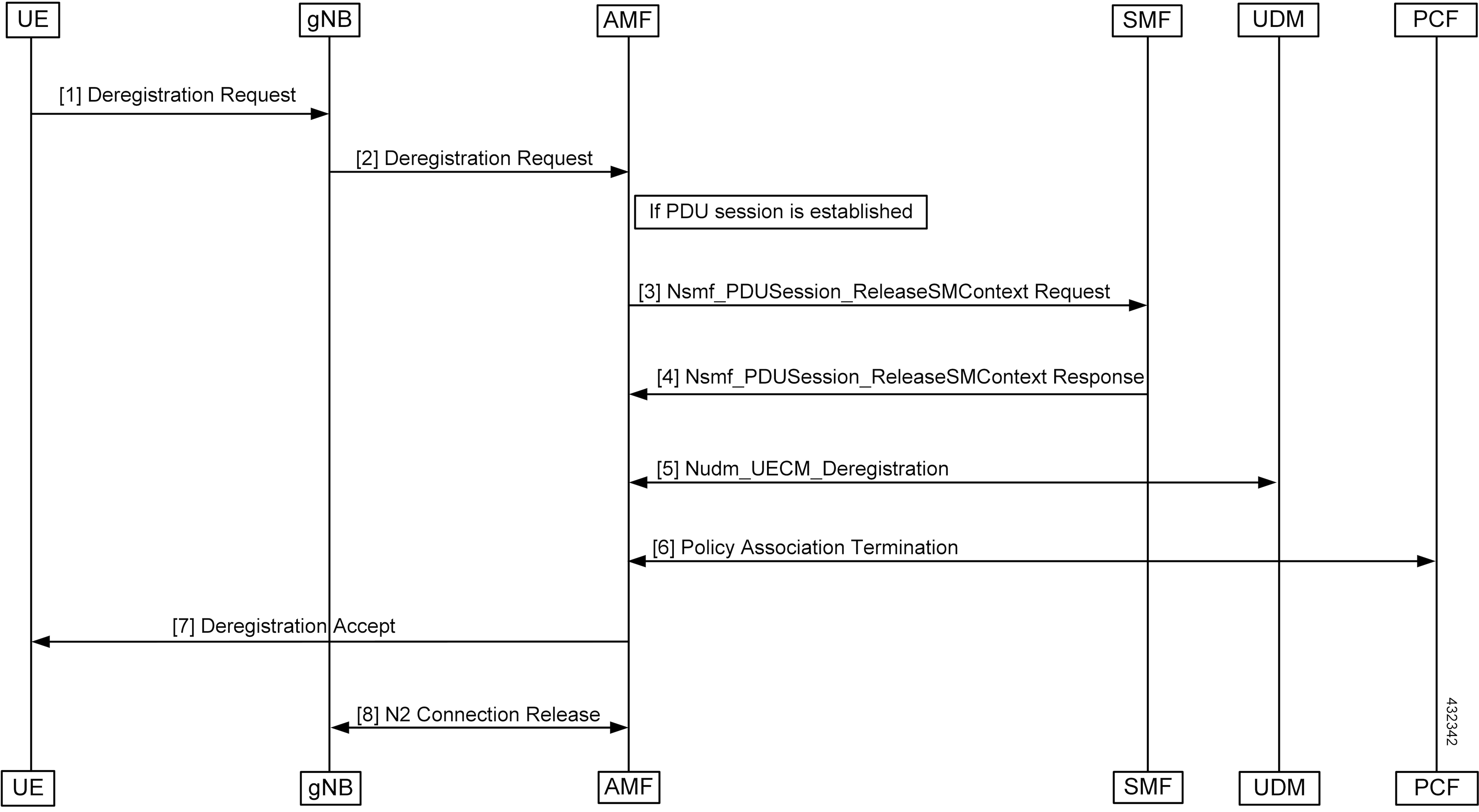
The deregistration procedure allows the UE to inform the network that it does not want to access the 5G data services.

Figure 10. UE-Initiated Deregistration Call Flow
Table 12. UE-Initiated Deregistration Call Flow Description

Step

Description

1, 2

The UE sends the NAS message Deregistration Request (5G-GUTI, Deregistration type, Access Type) to the AMF.

3

If the PDU session has been established, the AMF sends Nsmf_PDUSession_ReleaseSMContext (SUPI and PDU Session ID) to SMF. All the PDU sessions over the target access, which belong to the UE are released by the AMF by sending Nsmf_PDUSession_ReleaseSMContext Request (SUPI, PDU Session ID) message to the SMF for each PDU session.

4

The SMF releases all resources (for example, the IP address or prefixes that were allocated to the PDU session) and the corresponding User Plane resources. The SMF responds with Nsmf_PDUSession_ReleaseSMContext Response message.

5

The AMF invokes the Nudm_UECM_Deregistration service operation so that the UDM removes the association it had stored.

6

If there is any association with the PCF for this UE and the UE is no more registered over any access, the AMF performs an AMF-initiated AM Policy Association Termination procedure.

7

The AMF sends NAS message Deregistration Accept to UE depending on the Deregistration type i.e. if Deregistration type is switch-off, AMF does not send Deregistration Accept message.

8

The gNB exchanges the N2 UE Context Release with the AMF.

UDM-Initiated Deregistration Call Flow

This section describes the UDM-Initiated Deregistration call flow.

The UDM starts the deregistration process for an UE if the subscription is withdrawn for the UE. The UDM starts this procedure for operator-determined purposes to request the removal of a subscriber's RM context and PDU sessions of the UE.

Figure 11. UDM-Initiated Deregistration Call Flow
Table 13. UDM-Initiated Deregistration Call Flow Description

Step

Description

1

If the UDM wants to request the immediate deletion of a subscriber's contexts and PDU sessions, the UDM sends a Nudm_UECM_DeregistrationNotification (SUPI, Access Type, Removal Reason) message with Removal Reason set to Subscription Withdrawn to the registered AMF. If the AMF receives Nudm_UECM_DeregistrationNotification with Removal Reason as Subscription Withdrawn, the AMF executes the deregistration procedure over the access.

2

The AMF may explicitly deregister the UE by sending a Deregistration Request message (Deregistration type, Access Type) to the UE. The deregistration type may be set to Reregistration in which case the UE should reregister at the end of the deregistration procedure. If the Deregistration Request message is sent over 3GPP access and the UE is in CM-IDLE state in 3GPP access, the AMF pages the UE.

3

If the deregistration procedure is triggered by UDM, the AMF acknowledges the Nudm_UECM_DeRegistrationNotification to the UDM.

4

The AMF unsubscribes with the UDM using Nudm_SDM_Unsubscribe service operation.

5, 6

If the UE has any established PDU sessions, the UE-initiated Deregistration is performed.

7

If there is any association with the PCF for this UE and the UE is no more registered over any access, the AMF performs a AMF-initiated AM Policy Association Termination procedure

8

If the UE receives the Deregistration Request message from the AMF, the UE sends a Deregistration Accept message to the AMF. The NG-RAN forwards this NAS message to the AMF along with the TAI and cell identity of the cell which the UE is using.

9

The AMF exchanges the N2 UE Context Release with gNB.

AMF-Initiated Deregistration Call Flow

This section describes the AMF-Initiated Deregistration call flow.

If implicit detach timer expires, the AMF performs deregistration.

Figure 12. AMF-Initiated Deregistration Call Flow

In case of a clear subscriber, the AMF starts a deregistration procedure.

Table 14. AMF-Initiated Deregistration Call Flow Description

Step

Description

1

If the PDU session is established, the AMF sends Nsmf_PDUSession_ReleaseSMContext (SUPI, PDU, and Session ID) to SMF. All PDU sessions over the target access, which belong to the UE are released by the AMF by sending Nsmf_PDUSession_ReleaseSMContext Request (SUPI, PDU Session ID) message to the SMF for each PDU Session.

2

The SMF releases all resources (for example, the IP address/Prefixes that were allocated to the PDU Session) and the corresponding User Plane resources. The SMF responds with Nsmf_PDUSession_ReleaseSMContext Response message.

3

If there is any association with the PCF for this UE and the UE is no more registered over any access, the AMF performs an AMF-initiated AM Policy Association Termination procedure.

4

The AMF unsubscribes the UDM using the Nudm_SDM_Unsubscribe service operation.

5

The AMF invokes the Nudm_UECM_Deregistration service operation so that the UDM removes the association it had stored.

6

The AMF may explicitly deregister the UE by sending a Deregistration Request message (Deregistration type, Access Type) to the UE. The deregistration type may be set to reregistration in which case the UE should reregister at the end of the deregistration procedure. If the Deregistration Request message is sent over 3GPP access and the UE is in CM-IDLE state in 3GPP access, the AMF pages the UE.

7

After the UE receives the Deregistration Request message from the AMF, the UE sends a Deregistration Accept message to the AMF. The NG-RAN forwards this NAS message to the AMF along with the TAI and cell identity of the cell which the UE is using.

8

The AMF and gNB exchanges the N2 UE Context Release.

UE Identity Procedure for Authentication Failure Call Flow

This section describes the UE Identity Procedure for Authentication Failure call flow.

When the authentication fails at the Step 5 mentioned in the following call flow, the AMF triggers the Identity Request towards UE. Authentication is proceeded with the new UE identity.

Figure 13. UE Identity Procedure for Authentication Failure Call Flow
Table 15. UE Identity Procedure for Authentication Failure Call Flow Description

Step

Description

1

The UE sends a Registration Request to the gNB.

2

The gNB forwards the Registration Request with the AMF selection to the AMF.

3

The AUSF sends the authentication data along with the AUSF selection to the AMF.

4

The AMF sends an Authentication Request to the UE.

5

During the registration procedure when Authentication Response is received from the UE, the AMF examines the Authentication Response parameters and confirms that the authentication has failed. In such a case, the AMF triggers Identity Request to UE asking for its SUCI.

6

The UE sends the Identity Request message to AMF.

7

The UE responds with its SUCI in the Identity Response message to the AMF.

8

The AMF extracts fresh authentication data from AUSF using the SUCI of the subscriber.

9

The AMF sends Authentication-Request to the UE to initiate authentication of the UE identity.

10

The UE sends Authentication Response to the AMF to deliver a calculated authentication response to the network. The AMF verifies that the result received and if the result is as expected then the registration procedure starts.

11

The NAS security initiation is performed.

12

After the NAS security function setup is complete, the AMF starts the NGAP procedure to provide the 5G-AN with security context. The 5G-AN stores the security context and notifies it to the AMF. The 5G-AN uses the security context to protect the messages exchanged with the UE.

13

The AMF selects an UDM based on the PLMN info through the NRF query or static configuration and registers the UE with the UDM using Nudm_UECM_Registration. The UDM stores the AMF identity associated to the Access Type.

14

The AMF retrieves the Access and Mobility Subscription data using Nudm_SDM_Get. The AMF subscribes to be notified using Nudm_SDM_Subscribe when the data requested is modified.

15

The AMF selects PCF based on PLMN-info and slice- info and performs a Policy Association Establishment. The PCF sends policy data to the AMF with restrictions and other policies to be applied for the UE. The policies are not applied for UE and are stored in AMF.

16

The AMF sends a Registration Accept message to the UE indicating that the Registration Request is accepted. Registration Accept contains the following:

  • 5G-GUTI

  • Registration Area

  • Mobility restrictions

  • PDU Session status

  • Allowed NSSAI

  • Configured NSSAI for the Serving PLMN

  • Periodic Registration Update timer

  • Emergency Service Support indicator

  • Accepted DRX parameters

17

The UE sends a Registration Complete message to the AMF to acknowledge that a new 5G-GUTI was assigned.

UE Identity Procedure for Unknown Subscribers Call Flow

This section describes the UE Identity Procedure for Unknown Subscribers call flow.

When a Registration Request is received with unknown GUTI then AMF triggers an Identity Request towards UE and requests for an UE identity. Registration proceeds with the new UE identity.

Figure 14. UE Identity Procedure for Unknown Subscribers Call Flow
Table 16. UE Identity Procedure for Unknown Subscribers Call Flow Description

Step

Description

1

The UE sends the Registration Request with the GUTI to the gNB.

2

During the registration procedure, the AMF determines that the received GUTI is of a subscriber who is not present in AMF. In such case, AMF triggers an identity-request to UE asking for its SUCI.

3

The UE sends the identity-request message to the AMF.

4

The UE responds with its SUCI in the identity-response message to the AMF.

5

The AMF extracts fresh authentication data from the AUSF using the SUCI of subscriber.

6

The AMF sends Authentication Request to the UE to initiate authentication of the UE identity.

7

The UE sends Authentication Response to the AMF to deliver a calculated authentication response to the network. The AMF verifies that the result received and if the result is as expected then the registration procedure is proceeded.

8

The NAS security initiation is started.

9

After the NAS security function is set up, the AMF initiates the NGAP procedure to provide the 5G-AN with security context. The 5G-AN stores the security context and notifies it to the AMF. The 5G-AN uses the security context to protect the messages exchanged with the UE.

10

The AMF selects an UDM based on the PLMN info through the NRF query or static configuration and registers the UE with the UDM using Nudm_UECM_Registration. The UDM stores the AMF identity associated to the Access Type.

11

The AMF retrieves the Access and Mobility Subscription data using Nudm_SDM_Get.

The AMF subscribes to be notified using Nudm_SDM_Subscribe when the data requested is modified.

12

The AMF selects PCF based on PLMN-info and slice-info and performs a Policy Association Establishment. The PCF sends policy data to AMF with restrictions and other policies to be applied for the UE. Currently the policies are not applied for UE and are stored in AMF.

13

The AMF sends a Registration Accept message to the UE indicating that the Registration Request has been accepted. The Registration Accept contains the following:

  • 5G-GUTI

  • Registration Area

  • Mobility restrictions

  • PDU Session status

  • Allowed NSSAI

  • Configured NSSAI for the Serving PLMN

  • Periodic Registration Update timer

  • Emergency Service Support indicator

  • Accepted DRX parameters

14

The UE sends a Registration Complete message to the AMF to acknowledge that a new 5G-GUTI was assigned.

Configuring Compliance to 3GPP Specification

This section describes how to configure compliance to 3GPP specification.

Configuring Interfaces

The following are sample interface configurations. You need to configure interfaces based on your requirements.

config
profile nf-client nf-type ausf
 ausf-profile AUP1
  locality LOC1
   priority 30
   service name type nausf-auth
    endpoint-profile EP1
     capacity   30
     uri-scheme http
     endpoint-name EP1
      priority 56
      primary ip-address ipv4 <AUSF IP>
      primary ip-address port <Port number>
     exit
    exit
   exit
  exit
 exit
exit
exit
config
profile nf-client nf-type udm
 udm-profile UP1
  locality LOC1
   service name type nudm-sdm
    endpoint-profile EP1
     capacity   30
     uri-scheme http
     version
      uri-version v2
      exit
     exit
     endpoint-name EP1
      primary ip-address ipv4 <UDM IP Address>
      primary ip-address port <Port number>
     exit
    exit
   exit
exit
config
service name type nudm-uecm
    endpoint-profile EP1
     capacity   30
     uri-scheme http
     endpoint-name EP1
      primary ip-address ipv4 <UDM IP Address>
      primary ip-address port <Port number>
     exit
    exit
   exit
  exit
 exit
exit
exit
config
profile nf-client nf-type pcf
 pcf-profile PP1
  locality LOC1
   priority 30
   service name type npcf-am-policy-control
    endpoint-profile EP1
     capacity   30
     uri-scheme http
     endpoint-name EP1
      priority 56
      primary ip-address ipv4 <PCF IP Address>
      primary ip-address port <PCF Port number>
     exit
    exit
   exit
  exit
 exit
exit
exit
config
profile nf-client nf-type amf
 amf-profile AMF1
  locality LOC1
   priority 56
   service name type namf-comm
    endpoint-profile EP1
     capacity   30
     priority   30
     uri-scheme http
     endpoint-name EP1
      priority 30
      primary ip-address ipv4 <Peer AMF IP Address>
      primary ip-address port <Peer AMF Port number>
     exit
    exit
   exit
  exit
 exit
exit
exit
config
profile nf-client nf-type smf
 smf-profile SMF1
  locality LOC1
   priority 56
   service name type nsmf-pdusession
    endpoint-profile EP1
     capacity   30
     priority   30
     uri-scheme http
     endpoint-name EP1
      priority 30
      primary ip-address ipv4 <SMF IP Address>
      primary ip-address port <SMF Port number>
     exit
    exit
   exit
  exit
 exit
exit
exit

Sample Configuration

The following is a sample output of the interface configuration:

product amf(config-compliance-comp1)# show full
profile compliance comp1
   service namf-pdusession
      version uri v1
      version full 1.0.0
      version spec 15.2.0
product amf(config-service-namf-pdu)# compliance-profile comp1
product amf(config)# show full-configuration profile smf
profile amf smf1
   service name namf-pdu
   --------------------------------------------------------------
   compliance-profile comp1
   --------------------------------------------------------------
!
!