Introduzione
In questo documento viene illustrata una configurazione di esempio per Open Shortest Path First (OSPF) sul supporto di trasmissione, ad esempio Ethernet e Token Ring. Il comando show ip ospf interface verifica che OSPF venga eseguito su tutti i supporti di trasmissione come tipo di rete di trasmissione per impostazione predefinita.
Prerequisiti
Requisiti
I lettori di questo documento devono conoscere i seguenti argomenti:
Componenti usati
Le informazioni di questo documento si applicano a queste versioni software e hardware.
Le informazioni discusse in questo documento fanno riferimento a dispositivi usati in uno specifico ambiente di emulazione. Su tutti i dispositivi menzionati nel documento la configurazione è stata ripristinata ai valori predefiniti. Se la rete è operativa, valutare attentamente eventuali conseguenze derivanti dall'uso dei comandi.
Prodotti correlati
Questa configurazione può essere utilizzata anche con due router qualsiasi con almeno un'interfaccia Ethernet, Token Ring o FDDI.
Convenzioni
Per ulteriori informazioni sulle convenzioni usate, consultare il documento Cisco sulle convenzioni nei suggerimenti tecnici.
Configurazione
In questa sezione vengono presentate le informazioni che è possibile utilizzare per configurare le funzionalità descritte nel documento.
Nota: per ulteriori informazioni sui comandi menzionati in questo documento, consultare il documento Comandi OSPF o usare lo strumento di ricerca dei comandi (solo utenti registrati).
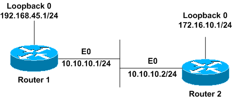
Esempio di rete
Il documento usa la seguente configurazione di rete.
Configurazioni
In questo documento vengono usate le seguenti configurazioni.
| Router1 |
interface Loopback0
 ip address 192.168.45.1 255.255.255.0
!
interface Ethernet0
 ip address 10.10.10.1 255.255.255.0
!
router ospf 1
 network 10.10.10.0 0.0.0.255 area 0

!--- OSPF is configured to run on the !--- Ethernet interface with an Area ID of 1.

! |
| Router2 |
interface Loopback0
 ip address 172.16.10.1 255.255.255.0
!
interface Ethernet0
 ip address 10.10.10.2 255.255.255.0
!
router ospf 1
 network 10.10.10.0 0.0.0.255 area 0

!--- OSPF is configured to run on the !--- Ethernet interface with an Area ID of 1.

! |
Verifica
In questa sezione viene spiegato come verificare che la configurazione funzioni correttamente.
Alcuni comandi show sono supportati dallo strumento Output Interpreter (solo utenti registrati); lo strumento permette di visualizzare un'analisi dell'output del comando show.
Router1#show ip ospf neighbor

 Neighbor ID   Pri    State          Dead Time      Address       Interface
 172.16.10.1    1     FULL/BDR       00:00:38     10.10.10.2      Ethernet0
Da questo output, lo stato del router adiacente è 'Full' nel router1 rispetto al router2 con ID router adiacente 172.16.10.1. Il router2 è un router designato per il backup (BDR) in questa rete broadcast. Per ulteriori informazioni sulla visualizzazione del comando show ip ospf neighbors, vedere What Does the show ip ospf neighbors Command Reveal?
Router1#show ip ospf interface ethernet 0
   Ethernet0 is up, line protocol is up
   Internet Address 10.10.10.1/24, Area 0
   Process ID 1, Router ID 192.168.45.1, Network Type BROADCAST, Cost: 10
   Transmit Delay is 1 sec, State DR, Priority 1
   Designated Router (ID) 192.168.45.1, Interface address 10.10.10.1
   Backup Designated router (ID) 172.16.10.1, Interface address 10.10.10.2
   Timer intervals configured, Hello 10, Dead 40, Wait 40, Retransmit 5
   Hello due in 00:00:00
   Index 2/2, flood queue length 0
   Next 0x0(0)/0x0(0)
   Last flood scan length is 2, maximum is 2
   Last flood scan time is 0 msec, maximum is 0 msec
   Neighbor Count is 1, Adjacent neighbor count is 1
   Adjacent with neighbor 172.16.10.1 (Backup Designated Router)
   Suppress hello for 0 neighbor(s)
Da questo output, si sa che il tipo di rete per l'interfaccia Ethernet 0 è broadcast. Per ulteriori informazioni sulla visualizzazione del comando show ip ospf interface, consultare il documento sulla funzionalità di visualizzazione del comando show ip ospf interface?
Analogamente, di seguito sono riportati gli output per i comandi show sul router2.
Router2#show ip ospf neighbor

 Neighbor ID    Pri    State       Dead Time       Address        Interface
 192.168.45.1    1     FULL/DR       00:00:31      10.10.10.1       Ethernet0
Come si evince dall'output del comando show ip ospf neighbors, il router 1 è il router designato (DR) in questa rete di trasmissione.
Router2#show ip ospf interface ethernet 0
     Ethernet0 is up, line protocol is up
     Internet Address 10.10.10.2/24, Area 0
     Process ID 1, Router ID 172.16.10.1, Network Type BROADCAST, Cost: 10
     Transmit Delay is 1 sec, State BDR, Priority 1
     Designated Router (ID) 192.168.45.1, Interface address 10.10.10.1
     Backup Designated router (ID) 172.16.10.1, Interface address 10.10.10.2
     Timer intervals configured, Hello 10, Dead 40, Wait 40, Retransmit 5
     Hello due in 00:00:00
     Index 1/1, flood queue length 0
     Next 0x0(0)/0x0(0)
     Last flood scan length is 1, maximum is 1
     Last flood scan time is 0 msec, maximum is 0 msec
     Neighbor Count is 1, Adjacent neighbor count is 1
     Adjacent with neighbor 192.168.45.1 (Designated Router)
     Suppress hello for 0 neighbor(s)
L'output del comando show ip ospf interface ethernet 0 restituito dal router2 mostra anche che il tipo di rete per l'interfaccia Ethernet 0 è broadcast.
Risoluzione dei problemi
In questa sezione vengono fornite informazioni utili per risolvere i problemi di configurazione.
Comandi per la risoluzione dei problemi
Alcuni comandi show sono supportati dallo strumento Output Interpreter (solo utenti registrati); lo strumento permette di visualizzare un'analisi dell'output del comando show.
Nota: prima di usare i comandi di debug, consultare il documento Informazioni importanti sui comandi di debug.
Quando si creano adiacenze tra due router, esistono vari stati. È possibile utilizzare il comando debug ip ospf adj per verificare i vari stati e la scelta di DR e BDR effettuata in una rete OSPF broadcast. Nelle versioni software Cisco IOS precedenti, è possibile usare il comando debug ip ospf adiacency. È necessario eseguire questo comando debug prima di stabilire la relazione con il router adiacente.
Questo output viene generato dalla prospettiva di Router1. Le parti dell'output in grassetto sono i vari stati attraversati dal processo adiacente.
Router1#debug ip ospf adj
OSPF adjacency events debugging is on

*Mar  1 01:41:23.319: OSPF: Rcv DBD from 172.16.10.1 on Ethernet0 seq 0x1F6C opt
 0x42 flag 0x7 len 32  mtu 1500 state INIT
*Mar  1 01:41:23.323: OSPF: 2 Way Communication to 172.16.10.1
 on Ethernet0, state 2WAY
*Mar  1 01:41:23.327: OSPF: Neighbor change Event on interface Ethernet0
*Mar  1 01:41:23.327: OSPF: DR/BDR election on Ethernet0
*Mar  1 01:41:23.331: OSPF: Elect BDR 172.16.10.1
*Mar  1 01:41:23.331: OSPF: Elect DR 192.168.45.1
*Mar  1 01:41:23.335:        DR: 192.168.45.1 (Id)   BDR: 172.16.10.1 (Id)
*Mar  1 01:41:23.339: OSPF: Send DBD to 172.16.10.1 on Ethernet0 seq 0x2552 opt
0x42 flag 0x7 len 32
*Mar  1 01:41:23.343: OSPF: First DBD and we are not SLAVE
*Mar  1 01:41:23.359: OSPF: Rcv DBD from 172.16.10.1 on Ethernet0 seq 0x2552 opt
 0x42 flag 0x2 len 52  mtu 1500 state EXSTART
*Mar  1 01:41:23.363: OSPF: NBR Negotiation Done. We are the MASTER
*Mar  1 01:41:23.367: OSPF: Send DBD to 172.16.10.1 on Ethernet0 seq 0x2553 opt
0x42 flag 0x3 len 72
*Mar  1 01:41:23.387: OSPF: Rcv DBD from 172.16.10.1 on Ethernet0 seq 0x2553 opt
 0x42 flag 0x0 len 32  mtu 1500 state EXCHANGE
*Mar  1 01:41:23.391: OSPF: Send DBD to 172.16.10.1 on Ethernet0 seq 0x2554 opt
0x42 flag 0x1 len 32
*Mar  1 01:41:23.411: OSPF: Rcv DBD from 172.16.10.1 on Ethernet0 seq 0x2554 opt
 0x42 flag 0x0 len 32  mtu 1500 state EXCHANGE
*Mar  1 01:41:23.415: OSPF: Exchange Done with 172.16.10.1 on Ethernet0
*Mar  1 01:41:23.419: OSPF: Synchronized with 172.16.10.1 on Ethernet0, state FULL
01:41:23: %OSPF-5-ADJCHG: Process 1, Nbr 172.16.10.1 on Ethernet0
 from LOADING to FULL, Loading Done
*Mar  1 01:41:23.879: OSPF: Build router LSA for area 0, router ID 192.168.45.1,
 seq 0x80000004
*Mar  1 01:41:23.923: OSPF: Build network LSA for Ethernet0, router ID 192.168.45.1
*Mar  1 01:41:25.503: OSPF: Neighbor change Event on interface Ethernet0
*Mar  1 01:41:25.507: OSPF: DR/BDR election on Ethernet0
*Mar  1 01:41:25.507: OSPF: Elect BDR 172.16.10.1
*Mar  1 01:41:25.511: OSPF: Elect DR 192.168.45.1
*Mar  1 01:41:25.511:        DR: 192.168.45.1 (Id)   BDR: 172.16.10.1 (Id)
Usare il comando debug ip ospf events per verificare il valore del timer hello, come mostrato nell'output di esempio.
Router1#debug ip ospf events
OSPF events debugging is on
Router1#
*Mar  1 04:04:11.926: OSPF: Rcv hello from 172.16.10.1 area 0 from
  Ethernet0 10.10.10.2
*Mar  1 04:04:11.930: OSPF: End of hello processing
*Mar  1 04:04:21.926: OSPF: Rcv hello from 172.16.10.1
  area 0 from Ethernet0 10.10.10.2
*Mar  1 04:04:21.930: OSPF: End of hello processing
*Mar  1 04:04:31.926: OSPF: Rcv hello from 172.16.10.1 area 0 from
  Ethernet0 10.10.10.2
*Mar  1 04:04:31.930: OSPF: End of hello processing
*Mar  1 04:04:41.926: OSPF: Rcv hello from 172.16.10.1 area 0 from
  Ethernet0 10.10.10.2
*Mar  1 04:04:41.930: OSPF: End of hello processing
*Mar  1 04:04:51.926: OSPF: Rcv hello from 172.16.10.1 area 0 from
  Ethernet0 10.10.10.2
*Mar  1 04:04:51.930: OSPF: End of hello processing
*Mar  1 04:05:01.926: OSPF: Rcv hello from 172.16.10.1 area 0 from
  Ethernet0 10.10.10.2
*Mar  1 04:05:01.930: OSPF: End of hello processing
*Mar  1 04:05:11.926: OSPF: Rcv hello from 172.16.10.1 area 0 from
  Ethernet0 10.10.10.2
*Mar  1 04:05:11.930: OSPF: End of hello processing
*Mar  1 04:05:21.926: OSPF: Rcv hello from 172.16.10.1 area 0 from
  Ethernet0 10.10.10.2
*Mar  1 04:05:21.930: OSPF: End of hello processing
Questo output mostra che il pacchetto hello viene scambiato ogni 10 secondi.
Informazioni correlate
 Feedback