MPLS VPN over ATM: con OSPF sul lato cliente (con area 0)
Sommario
Introduzione
In questo documento viene fornito un esempio di configurazione di MPLS (Multiprotocol Label Switching) VPN (Virtual Private Network) su ATM quando Open Shortest Path First (OSPF) è presente sul lato cliente, con area 0.
Operazioni preliminari
Convenzioni
Per ulteriori informazioni sulle convenzioni usate, consultare il documento Cisco sulle convenzioni nei suggerimenti tecnici.
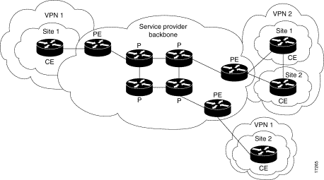
Le lettere seguenti rappresentano i diversi tipi di router e switch utilizzati:
-
P: Router di base del provider
-
PE: Router perimetrale del provider
-
CE: Router perimetrale del cliente
-
C: Router del cliente
Il diagramma mostra una configurazione tipica basata sulle seguenti convenzioni:

Prerequisiti
Non sono previsti prerequisiti specifici per questo documento.
Componenti usati
Le informazioni fornite in questo documento si basano sulle versioni software e hardware riportate di seguito.
-
Router PE:
-
Software - Software Cisco IOS® versione 12.1(3)T . Le funzionalità VPN di MPLS sono disponibili nella versione 12.0(5)T. Il protocollo OSPF come protocollo di routing PE-CE viene visualizzato nella release 12.0(7)T.
-
Hardware: router Cisco 3660 o 7206. Per ulteriori informazioni sugli altri componenti hardware che è possibile utilizzare, consultare la guida alla progettazione di MPLS per ATM.
-
-
Router CE: È possibile utilizzare qualsiasi router in grado di scambiare informazioni di routing con il relativo router PE.
-
Router e switch IP: La funzione di integrazione VPN di MPLS risiede solo sul bordo della rete MPLS, quindi è possibile utilizzare qualsiasi switch compatibile con MPLS. In questa configurazione di esempio, il cloud MPLS è composto da un router switch Multiservice ATM 8540 (MSR) e da un LightStream 1010. Se si utilizza Cisco LightStream 1010, si consiglia di utilizzare la versione software WA4.8d o successive. Inoltre, è possibile usare altri switch ATM come Cisco BPX 8650 o MGX 8850 nella rete principale ATM.
Le informazioni discusse in questo documento fanno riferimento a dispositivi usati in uno specifico ambiente di emulazione. Su tutti i dispositivi menzionati nel documento la configurazione è stata ripristinata ai valori predefiniti. Se la rete è operativa, valutare attentamente eventuali conseguenze derivanti dall'uso dei comandi.
Nozioni di base
La funzionalità VPN, se utilizzata con MPLS, consente a più siti di interconnettersi in modo trasparente tramite la rete di un provider di servizi. Una rete di provider di servizi può supportare diverse VPN IP. Ognuno di questi elementi viene visualizzato agli utenti come una rete privata, separata da tutte le altre reti. All'interno di una VPN, ogni sito può inviare pacchetti IP a qualsiasi altro sito della stessa VPN.
Ogni VPN è associata a una o più istanze di routing o inoltro VPN (VRF). Un VRF è costituito da una tabella di routing IP, una tabella EF (Cisco Express Forwarding) derivata e un set di interfacce che utilizzano questa tabella di inoltro.
Il router gestisce un routing separato e una tabella Cisco EF per ciascun VRF. In questo modo si evita che le informazioni vengano inviate all'esterno della VPN e si consente l'utilizzo della stessa subnet in più VPN senza causare problemi di indirizzi IP duplicati.
Il router che utilizza il Border Gateway Protocol (BGP) distribuisce le informazioni di routing VPN utilizzando le community estese BGP.
Per ulteriori informazioni sulla propagazione degli aggiornamenti tramite VPN, vedere gli URL seguenti:
Utilizzo di OSPF
Tradizionalmente, un'elaborata rete OSPF è costituita da un'area backbone (area 0) e da un certo numero di aree connesse a questa backbone tramite un ABR (Area Border Router).
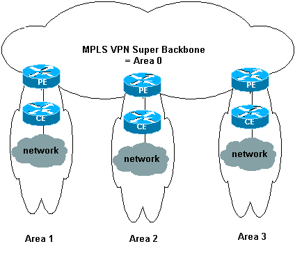
Utilizzando una backbone MPLS per VPN con OSPF sul sito del cliente, è possibile introdurre un terzo livello nella gerarchia del modello OSPF. Questo terzo livello è denominato MPLS VPN Super Backbone.
In casi semplici, la MPLS VPN Super Backbone è combinata con la backbone area 0 tradizionale. Ciò significa che non esiste una backbone area 0 sulla rete del cliente, poiché la backbone MPLS VPN Super svolge lo stesso ruolo della backbone area 0. Come si vede nel seguente diagramma:

In questo diagramma:
-
I router PE sono ABR e ASBR (Autonomous System Boundary Router).
-
I router CE sono semplici router OSPF.
-
Le informazioni VPN vengono trasportate dalle comunità estese BGP da PE ad altri PE e reiniettate nelle aree OSPF come LSA (Link-State Advertisements) di Summary Network (tipo 3).
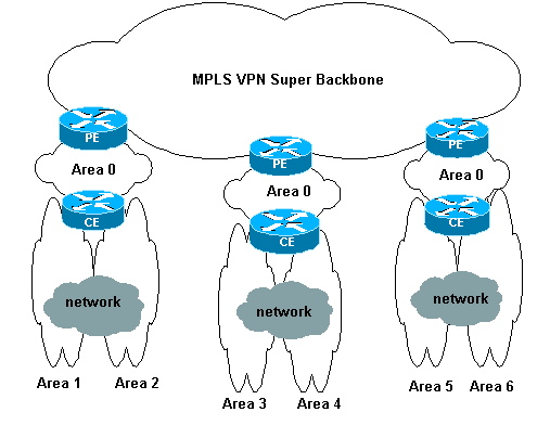
MPLS VPN Super Backbone consente inoltre ai clienti di utilizzare più backbone area 0 nei propri siti. Ogni sito può avere un'area 0 separata purché sia connesso alla backbone MPLS VPN Super. Il risultato è lo stesso di una backbone 0 dell'area partizionata. Come si vede nel seguente diagramma:

In questo caso:
-
I router PE sono router ABR e ASBR.
-
I router CE sono router ABR.
-
Le LSA contenenti informazioni VPN vengono trasportate da PE ad altri PE utilizzando le community estese BGP. Nelle LSA Summary Network (tipo 3), le informazioni vengono trasportate tra PE e CE.
Questa configurazione di esempio si basa sulla seconda impostazione mostrata sopra. È possibile trovare una configurazione di esempio che utilizza la prima configurazione in MPLS VPN over ATM: con OSPF sul lato cliente (senza area 0).
Le informazioni OSPF vengono trasportate con attributi della community estesi BGP (incluso uno che identifica la rete OSPF). Ogni VPN deve avere un proprio processo OSPF. Per specificare questa condizione, eseguire il comando seguente:
router ospf <ID processo> vrf <nome istanza inoltro o routing VPN>
Configurazione
In questa sezione vengono presentate le informazioni necessarie per configurare le funzionalità descritte più avanti nel documento.
Nota: per ulteriori informazioni sui comandi menzionati in questo documento, usare lo strumento di ricerca dei comandi (solo utenti registrati).
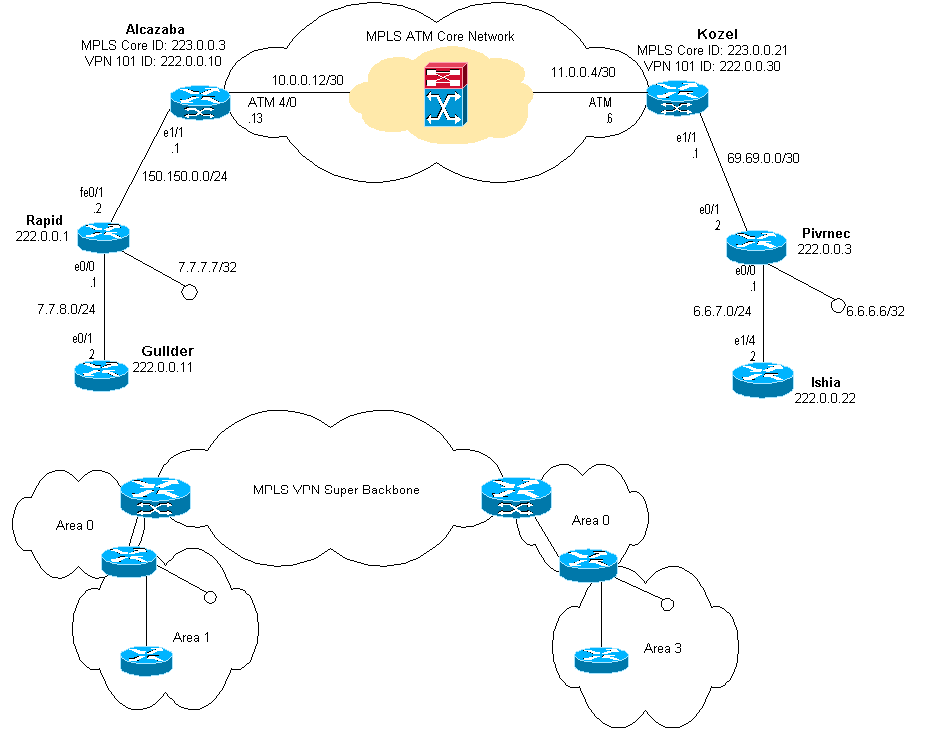
Esempio di rete
Questo documento utilizza le impostazioni di rete mostrate nel diagramma sottostante.

Procedura di configurazione
Anche la documentazione di Cisco IOS (MPLS Virtual Private Network) descrive questa procedura di configurazione.
Parte I
Verificare che ip cef sia abilitato. Se si usa un router Cisco 7500, verificare che ip cef distribuito sia abilitato. Sui PE, una volta configurato MPLS:
-
Creare un VRF per ciascuna VPN connessa utilizzando il comando ip vrf <nome istanza routing/inoltro VPN>. Quando si esegue questa operazione:
-
Utilizzare il comando seguente per specificare il distinguitore di route corretto utilizzato per la VPN. Questa opzione viene utilizzata per estendere l'indirizzo IP in modo da poter identificare la VPN a cui appartiene.
rd <identificatore route VPN>
-
Impostare le proprietà di importazione ed esportazione per le community estese BGP. Vengono utilizzati per filtrare il processo di importazione ed esportazione.
route-target [export|import|both] <community estesa VPN di destinazione>
-
-
Configurare i dettagli di inoltro per le rispettive interfacce usando questo comando:
ip vrf forwarding <nome tabella>
Ricordarsi di configurare l'indirizzo IP dopo questa operazione.
-
A seconda del protocollo di routing PE-CE in uso, eseguire una o più delle operazioni seguenti:
-
Configurare le route statiche nel modo seguente:
ip route vrf vrf-name prefix mask [indirizzo-hop successivo] [interfaccia {interface-number}]
-
Configurare il protocollo RIP (Routing Information Protocol) utilizzando il comando:
address-family ipv4 vrf <nome istanza routing/inoltro VPN>
Al termine, immettere i normali comandi di configurazione RIP.
Si noti che:
-
Applicato solo alle interfacce di inoltro per il VRF corrente.
-
È necessario ridistribuire il BGP corretto in RIP. Quando si esegue questa operazione, è necessario specificare anche la metrica utilizzata.
-
-
Dichiarare le informazioni sui router adiacenti BGP.
-
Configurare OSPF usando il nuovo comando Cisco IOS:
router ospf <ID processo> vrf <nome istanza routing/inoltro VPN>.
Si noti che:
-
Applicato solo alle interfacce di inoltro per il VRF corrente.
-
È necessario ridistribuire il BGP corretto in OSPF. Quando si esegue questa operazione, è necessario specificare anche la metrica utilizzata.
-
Una volta che il processo OSPF è stato attribuito a un VRF, questo numero di processo viene sempre utilizzato per quel particolare VRF. Ciò vale anche se non viene specificato nella riga di comando.
-
Parte II
Configurare il protocollo BGP tra i router PE. Esistono diversi modi per configurare BGP, ad esempio utilizzando il reflector di route o i metodi di confederazione. Il metodo utilizzato in questo caso, ovvero la configurazione diretta dei nodi adiacenti, è il più semplice e il meno scalabile.
-
Dichiarate i diversi vicini.
-
Immettere il nome dell'istanza di routing/inoltro VPN per la famiglia di indirizzi ipv4> per ogni VPN presente su questo router PE. Eseguire una o più delle seguenti operazioni, se necessario:
-
Ridistribuire le informazioni di routing statiche.
-
Ridistribuire le informazioni di routing RIP.
-
Ridistribuire le informazioni di routing OSPF.
-
Attivare BGP adiacente con i router CE.
-
-
Immettere il valore per address-family vpnv4 Mode, e:
-
Attivare i vicini.
-
Specificare che deve essere utilizzata la community estesa. Questa operazione è obbligatoria.
-
Configurazioni
Nota: sono incluse solo le parti rilevanti dell'output riportato di seguito.
| Alcazaba |
|---|
ip cef ! ip vrf vpn1 rd 1:101 route-target export 1:101 route-target import 1:101 ! interface Loopback0 ip address 223.0.0.3 255.255.255.255 ! interface Loopback1 ip vrf forwarding vpn1 ip address 222.0.0.10 255.255.255.255 ! interface Ethernet1/1 ip vrf forwarding vpn1 ip address 150.150.0.1 255.255.255.0 no ip mroute-cache ! interface ATM4/0 no ip address no ip mroute-cache no atm ilmi-keepalive ! interface ATM4/0.1 tag-switching ip address 10.0.0.13 255.255.255.252 tag-switching atm vpi 2-4 tag-switching ip ! router ospf 1 log-adjacency-changes network 10.0.0.0 0.0.0.255 area 0 network 150.150.0.0 0.0.0.255 area 0 network 223.0.0.3 0.0.0.0 area 0 ! router ospf 2 vrf vpn1 log-adjacency-changes redistribute bgp 1 metric-type 1 subnets network 150.150.0.0 0.0.0.255 area 0 network 222.0.0.0 0.0.0.255 area 0 ! router bgp 1 neighbor 223.0.0.21 remote-as 1 neighbor 223.0.0.21 update-source Loopback0 ! address-family ipv4 vrf vpn1 redistribute ospf 2 no auto-summary no synchronization exit-address-family ! address-family vpnv4 neighbor 223.0.0.21 activate neighbor 223.0.0.21 send-community extended exit-address-family ! |
| Kozel |
|---|
! ip cef ! ip vrf vpn1 rd 1:101 route-target export 1:101 route-target import 1:101 ! interface Loopback0 ip address 223.0.0.21 255.255.255.255 ! interface Loopback1 ip vrf forwarding vpn1 ip address 222.0.0.30 255.255.255.255 ! interface Ethernet1/1 ip vrf forwarding vpn1 ip address 69.69.0.1 255.255.255.252 no ip mroute-cache tag-switching ip ! interface ATM4/0 no ip address no atm scrambling cell-payload no atm ilmi-keepalive pvc qsaal 0/5 qsaal ! pvc ilmi 0/16 ilmi ! ! interface ATM4/0.1 tag-switching ip address 11.0.0.6 255.255.255.252 tag-switching atm vpi 2-4 tag-switching ip ! router ospf 1 log-adjacency-changes network 11.0.0.0 0.0.0.255 area 0 network 223.0.0.21 0.0.0.0 area 0 ! router ospf 2 vrf vpn1 log-adjacency-changes redistribute bgp 1 metric-type 1 subnets network 69.69.0.0 0.0.0.255 area 0 network 222.0.0.0 0.0.0.255 area 0 ! router bgp 1 neighbor 223.0.0.3 remote-as 1 neighbor 223.0.0.3 update-source Loopback0 neighbor 223.0.0.11 remote-as 1 neighbor 223.0.0.11 update-source Loopback0 ! address-family ipv4 vrf vpn1 redistribute ospf 2 no auto-summary no synchronization exit-address-family ! address-family vpnv4 neighbor 223.0.0.3 activate neighbor 223.0.0.3 send-community extended neighbor 223.0.0.11 activate neighbor 223.0.0.11 send-community extended exit-address-family ! |
| Rapido |
|---|
! interface Loopback0 ip address 222.0.0.1 255.255.255.255 ! interface Loopback2 ip address 7.7.7.7 255.255.255.0 ! interface FastEthernet0/0 ip address 7.7.8.1 255.255.255.0 duplex auto speed auto ! interface FastEthernet0/1 ip address 150.150.0.2 255.255.255.0 duplex auto speed auto ! router ospf 1 network 7.7.7.7 0.0.0.0 area 1 network 150.150.0.0 0.0.0.255 area 0 network 222.0.0.1 0.0.0.0 area 1 ! |
| Pivrnec |
|---|
! interface Loopback0 ip address 222.0.0.3 255.255.255.255 ! interface Loopback1 ip address 6.6.6.6 255.255.255.255 ! interface FastEthernet0/0 ip address 6.6.7.1 255.255.255.0 duplex auto speed auto ! interface FastEthernet0/1 ip address 69.69.0.2 255.255.255.252 duplex auto speed auto ! router ospf 1 log-adjacency-changes network 6.6.6.6 0.0.0.0 area 3 network 69.69.0.0 0.0.0.255 area 0 network 222.0.0.3 0.0.0.0 area 3 ! |
| Fiorino |
|---|
! interface Loopback0 ip address 222.0.0.11 255.255.255.255 ! interface Ethernet0/1 ip address 7.7.8.2 255.255.255.0 ! router ospf 2 network 7.7.8.0 0.0.0.255 area 1 network 222.0.0.0 0.0.0.255 area 1 ! |
| Ischia |
|---|
! interface Loopback0 ip address 222.0.0.22 255.255.255.255 ! interface Ethernet1/4 ip address 6.6.7.2 255.255.255.0 ! router ospf 1 log-adjacency-changes network 6.6.7.0 0.0.0.255 area 3 network 222.0.0.0 0.0.0.255 area 3 ! |
Verifica
Le informazioni contenute in questa sezione permettono di verificare che la configurazione funzioni correttamente.
Alcuni comandi show sono supportati dallo strumento Output Interpreter (solo utenti registrati); lo strumento permette di visualizzare un'analisi dell'output del comando show.
-
show ip route vrf <nome istanza routing o inoltro VPN>
-
show ip bgp vpnv4 vrf <nome istanza routing o inoltro VPN> <A.B.C.D>
-
show ip ospf <numero ID processo>
-
show ip ospf <process ID number> interface
-
show ip ospf <process ID number> database
-
show tag-switching forwarding-table vrf <nome istanza routing o inoltro VPN>
Eseguire i primi due comandi sopra riportati per visualizzare il VRF di una VPN specifica sul router PE.
Comandi specifici OSPF
Comandi per un router PE
I comandi seguenti mostrano le informazioni OSPF per il VRF corrispondente. Le parti più importanti dell'output sottostante sono visualizzate in grassetto.
Nota: non è necessario specificare il VRF quando si eseguono questi comandi.
Alcazaba#show ip ospf 2
 Routing Process "ospf 2" with ID 222.0.0.10
 Supports only single TOS(TOS0) routes
 Supports opaque LSA
 Connected to MPLS VPN Superbackbone
 It is an area border and autonomous system boundary router
 Redistributing External Routes from,
    bgp 1, includes subnets in redistribution
 SPF schedule delay 5 secs, Hold time between two SPFs 10 secs
 Minimum LSA interval 5 secs. Minimum LSA arrival 1 secs
 Number of external LSA 0. Checksum Sum 0x0
 Number of opaque AS LSA 0. Checksum Sum 0x0
 Number of DCbitless external and opaque AS LSA 0
 Number of DoNotAge external and opaque AS LSA 0
 Number of areas in this router is 1. 1 normal 0 stub 0 nssa
 External flood list length 0
    Area BACKBONE(0)
        Number of interfaces in this area is 2
        Area has no authentication
        SPF algorithm executed 4 times
        Area ranges are
        Number of LSA 13. Checksum Sum 0x715C5
        Number of opaque link LSA 0. Checksum Sum 0x0
        Number of DCbitless LSA 0
        Number of indication LSA 0
        Number of DoNotAge LSA 0
        Flood list length 0

Alcazaba#show ip ospf 2 database

            OSPF Router with ID (222.0.0.10) (Process ID 2)

                Router Link States (Area 0)

Link ID         ADV Router      Age         Seq#       Checksum Link count
222.0.0.1       222.0.0.1       272         0x80000009 0xCA39   1
222.0.0.10      222.0.0.10      197         0x80000003 0xFCFF   2

                Net Link States (Area 0)

Link ID         ADV Router      Age         Seq#       Checksum
150.150.0.1     222.0.0.10      197         0x80000002 0xEA6E

                Summary Net Link States (Area 0)

Link ID         ADV Router      Age         Seq#       Checksum
6.6.6.6         222.0.0.10      197         0x80000002 0x4768
6.6.7.0         222.0.0.10      750         0x80000001 0xD4D7
7.7.7.7         222.0.0.1       272         0x80000002 0x72CC
7.7.8.0         222.0.0.1       1003        0x80000003 0x635
69.69.0.0       222.0.0.10      197         0x80000002 0x2228
222.0.0.1       222.0.0.1       272         0x80000002 0x5A21
222.0.0.3       222.0.0.10      197         0x80000004 0xE8FA
222.0.0.11      222.0.0.1       1010        0x80000001 0x5C0C
222.0.0.22      222.0.0.10      752         0x80000001 0x9435
222.0.0.30      222.0.0.10      199         0x80000002 0x795B

Alcazaba#show ip ospf 2 interface
Loopback1 is up, line protocol is up
  Internet Address 222.0.0.10/32, Area 0
  Process ID 2, Router ID 222.0.0.10, Network Type LOOPBACK, Cost: 1
  Loopback interface is treated as a stub Host
Ethernet1/1 is up, line protocol is up
  Internet Address 150.150.0.1/24, Area 0
  Process ID 2, Router ID 222.0.0.10, Network Type BROADCAST, Cost: 10
  Transmit Delay is 1 sec, State DR, Priority 1
  Designated Router (ID) 222.0.0.10, Interface address 150.150.0.1
  Backup Designated router (ID) 222.0.0.1, Interface address 150.150.0.2
  Timer intervals configured, Hello 10, Dead 40, Wait 40, Retransmit 5
    Hello due in 00:00:08
  Index 1/1, flood queue length 0
  Next 0x0(0)/0x0(0)
  Last flood scan length is 6, maximum is 6
  Last flood scan time is 0 msec, maximum is 0 msec
  Neighbor Count is 1, Adjacent neighbor count is 1
    Adjacent with neighbor 222.0.0.1  (Backup Designated Router)
  Suppress hello for 0 neighbor(s)
Comandi per un router CE
In questo caso, il router CE è un ABR perché è collegato anche a un'altra area. Se questo router avesse solo interfacce nell'area 0, sarebbe un router normale, non un ABR o ASBR.
rapid#show ip ospf
 Routing Process "ospf 1" with ID 222.0.0.1
 Supports only single TOS(TOS0) routes
 Supports opaque LSA
 It is an area border router
 SPF schedule delay 5 secs, Hold time between two SPFs 10 secs
 Minimum LSA interval 5 secs. Minimum LSA arrival 1 secs
 Number of external LSA 0. Checksum Sum 0x0
 Number of opaque AS LSA 0. Checksum Sum 0x0
 Number of DCbitless external and opaque AS LSA 0
 Number of DoNotAge external and opaque AS LSA 0
 Number of areas in this router is 2. 2 normal 0 stub 0 nssa
 External flood list length 0
    Area BACKBONE(0)
        Number of interfaces in this area is 1
        Area has no authentication
        SPF algorithm executed 14 times
        Area ranges are
        Number of LSA 13. Checksum Sum 0x715C5
        Number of opaque link LSA 0. Checksum Sum 0x0
        Number of DCbitless LSA 0
        Number of indication LSA 0
        Number of DoNotAge LSA 0
        Flood list length 0
    Area 1
        Number of interfaces in this area is 3
        Area has no authentication
        SPF algorithm executed 48 times
        Area ranges are
        Number of LSA 16. Checksum Sum 0x8CCBE
        Number of opaque link LSA 0. Checksum Sum 0x0
        Number of DCbitless LSA 0
        Number of indication LSA 0
        Number of DoNotAge LSA 0
        Flood list length 0

rapid#show ip ospf database

       OSPF Router with ID (222.0.0.1) (Process ID 1)

                Router Link States (Area 0)

Link ID         ADV Router      Age         Seq#       Checksum Link count
222.0.0.1       222.0.0.1       331         0x80000009 0xCA39   1
222.0.0.10      222.0.0.10      259         0x80000003 0xFCFF   2

                Net Link States (Area 0)

Link ID         ADV Router      Age         Seq#       Checksum
150.150.0.1     222.0.0.10      259         0x80000002 0xEA6E

                Summary Net Link States (Area 0)

Link ID         ADV Router      Age         Seq#       Checksum
6.6.6.6         222.0.0.10      259         0x80000002 0x4768
6.6.7.0         222.0.0.10      812         0x80000001 0xD4D7
7.7.7.7         222.0.0.1       331         0x80000002 0x72CC
7.7.8.0         222.0.0.1       1062        0x80000003 0x635
69.69.0.0       222.0.0.10      259         0x80000002 0x2228
222.0.0.1       222.0.0.1       331         0x80000002 0x5A21
222.0.0.3       222.0.0.10      260         0x80000004 0xE8FA
222.0.0.11      222.0.0.1       1069        0x80000001 0x5C0C
222.0.0.22      222.0.0.10      813         0x80000001 0x9435
222.0.0.30      222.0.0.10      260         0x80000002 0x795B

                Router Link States (Area 1)

Link ID         ADV Router      Age         Seq#       Checksum Link count
222.0.0.1       222.0.0.1       1078        0x80000029 0x658E   3
222.0.0.10      222.0.0.10      2962        0x80000003 0xFCFF   2
222.0.0.11      222.0.0.11      1080        0x80000003 0xA97F   2

                Net Link States (Area 1)

Link ID         ADV Router      Age         Seq#       Checksum
7.7.8.2         222.0.0.11      1081        0x80000001 0x93DA
150.150.0.1     222.0.0.10      2962        0x80000002 0xEA6E

                Summary Net Link States (Area 1)

Link ID         ADV Router      Age         Seq#       Checksum
6.6.6.6         222.0.0.1       332         0x80000002 0x69C5
6.6.6.6         222.0.0.10      2720        0x80000002 0x4768
6.6.7.0         222.0.0.1       820         0x80000001 0xF635
69.69.0.0       222.0.0.1       341         0x80000002 0x4485
150.150.0.0     222.0.0.1       341         0x80000004 0x57CB
222.0.0.3       222.0.0.1       341         0x80000002 0xF56
222.0.0.3       222.0.0.10      2727        0x80000002 0xECF8
222.0.0.10      222.0.0.1       341         0x80000002 0x6404
222.0.0.22      222.0.0.1       820         0x80000001 0xB692
222.0.0.30      222.0.0.1       341         0x80000002 0x9BB8

                Summary ASB Link States (Area 1)

Link ID         ADV Router      Age         Seq#       Checksum
222.0.0.10      222.0.0.1       341         0x80000002 0x4C1C
Comandi per un router C
Utilizzare il comando seguente per visualizzare la tabella di routing IP:
Guilder#show ip route
Codes: C - connected, S - static, I - IGRP, R - RIP, M - mobile, B - BGP
       D - EIGRP, EX - EIGRP external, O - OSPF, IA - OSPF inter area
       N1 - OSPF NSSA external type 1, N2 - OSPF NSSA external type 2
       E1 - OSPF external type 1, E2 - OSPF external type 2, E - EGP
       i - IS-IS, L1 - IS-IS level-1, L2 - IS-IS level-2, ia - IS-IS inter area
       * - candidate default, U - per-user static route, o - ODR
       P - periodic downloaded static route

Gateway of last resort is not set

     69.0.0.0/30 is subnetted, 1 subnets
O IA    69.69.0.0 [110/21] via 7.7.8.1, 00:06:33, Ethernet0/1
     222.0.0.0/32 is subnetted, 6 subnets
O IA    222.0.0.30 [110/21] via 7.7.8.1, 00:06:33, Ethernet0/1
O IA    222.0.0.22 [110/41] via 7.7.8.1, 00:06:33, Ethernet0/1
O IA    222.0.0.10 [110/21] via 7.7.8.1, 00:06:33, Ethernet0/1
C       222.0.0.11 is directly connected, Loopback0
O IA    222.0.0.3 [110/31] via 7.7.8.1, 00:06:33, Ethernet0/1
O       222.0.0.1 [110/11] via 7.7.8.1, 00:06:33, Ethernet0/1
     6.0.0.0/8 is variably subnetted, 2 subnets, 2 masks
O IA    6.6.6.6/32 [110/31] via 7.7.8.1, 00:06:34, Ethernet0/1
O IA    6.6.7.0/24 [110/40] via 7.7.8.1, 00:06:34, Ethernet0/1
     7.0.0.0/8 is variably subnetted, 2 subnets, 2 masks
O       7.7.7.7/32 [110/11] via 7.7.8.1, 00:06:35, Ethernet0/1
C       7.7.8.0/24 is directly connected, Ethernet0/1
     10.0.0.0/22 is subnetted, 1 subnets
C       10.200.8.0 is directly connected, Ethernet0/0
     150.150.0.0/24 is subnetted, 1 subnets
O IA    150.150.0.0 [110/20] via 7.7.8.1, 00:06:35, Ethernet0/1
Etichette MPLS
Confermare che lo stack di etichette alla voce Label Switch Router (LSR) contenga due etichette, come indicato di seguito:
Alcazaba#show tag-switching forwarding-table vrf vpn1 6.6.7.2 detail
Local  Outgoing    Prefix            Bytes tag  Outgoing   Next Hop
tag    tag or VC   or Tunnel Id      switched   interface
None   2/41        6.6.7.0/24        0          AT4/0.1    point2point
        MAC/Encaps=4/12, MTU=4466, Tag Stack{2/41(vcd=10) 29}
        000A8847 0000A0000001D000
A questo punto, verificare che vengano visualizzate sull'LSR di uscita:
Kozel#show tag-switching forwarding-table vrf vpn1 6.6.7.2 detail
Local  Outgoing    Prefix            Bytes tag  Outgoing   Next Hop
tag    tag or VC   or Tunnel Id      switched   interface
29     Untagged    6.6.7.0/24[V]     1466       Et1/1      69.69.0.2
        MAC/Encaps=0/0, MTU=1500, Tag Stack{}
        VPN route: vpn1
    Per-packet load-sharing
Comandi test
A questo punto, è possibile usare il comando ping per verificare che tutto funzioni correttamente:
Ischia#ping 222.0.0.11

Type escape sequence to abort.
Sending 5, 100-byte ICMP Echos to 222.0.0.11, timeout is 2 seconds:
!!!!!
Success rate is 100 percent (5/5), round-trip min/avg/max = 1/3/4 ms
Ischia#trac
Ischia#traceroute 222.0.0.11

Type escape sequence to abort.
Tracing the route to 222.0.0.11

  1 6.6.7.1 0 msec 0 msec 0 msec
  2 69.69.0.1 0 msec 0 msec 0 msec
  3 150.150.0.1 4 msec 4 msec 0 msec
  4 150.150.0.2 4 msec 0 msec 0 msec
  5 7.7.8.2 4 msec *  0 msec
Risoluzione dei problemi
Al momento non sono disponibili informazioni specifiche per la risoluzione dei problemi di questa configurazione.
Informazioni correlate
Cronologia delle revisioni
| Revisione | Data di pubblicazione | Commenti |
|---|---|---|
1.0 |
05-Jun-2005 |
Versione iniziale |
 Feedback