MPLS VPN over ATM:カスタマー側の OSPF の使用(エリア 0 なし)
内容
概要
このドキュメントでは、エリア 0 なしで Open Shortest Path First(OSPF)がお客様側に存在する場合の ATM 上でのマルチプロトコル ラベル スイッチング(MPLS)VPN の設定例を紹介します。
バーチャル プライベート ネットワーク(VPN)機能を MPLS と併用すると、複数のサイトがサービス プロバイダーのネットワークを通じてトランスペアレントに相互接続できるようになります。1 つのサービス プロバイダー ネットワークで複数の IP VPN をサポートできます。各 VPN は、ユーザからは他のすべてのネットワークから切り離されたプライベート ネットワークのように見えます。1 つの VPN を通じて、各サイトは同じ VPN 内にある他のサイトに IP パケットを送信できます。
前提条件
要件
各 VPN は 1 つ以上の VPN Routing or Forwarding instance(VRF; VPN ルーティング/転送インスタンス)に関連付けられます。VRF は、IP ルーティング テーブル、Cisco Express Fowarding(CEF)テーブル、次の転送テーブルを使用する一連のインターフェイスで構成されています。
ルータは VRF ごとに異なるルーティング テーブルと CEF テーブルを保持します。これにより、VPN の外では情報は送信できませんが、重複 IP アドレスの問題なしに同じサブネットを複数の VPN で使用できます。
ボーダー ゲートウェイ プロトコル(BGP)を使用するルータは、BGP 拡張コミュニティとの VPN ルーティング情報を配信します。
VPN 経由でのアップデートの伝播に関する詳細については、次の URL を参照してください。
ハードウェアとソフトウェアのバージョン
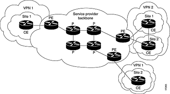
次の文字は使用されるルータおよびスイッチのタイプを表します。
-
P:プロバイダー コア ルータ
-
PE:プロバイダー エッジ ルータ
-
CE:カスタマー エッジ ルータ
-
C :カスタマー ルータ
次のソフトウェアおよびハードウェアのバージョンによる構成で、開発およびテストを行いました。
-
PE ルータ:
-
ソフトウェア:Cisco IOS® ソフトウェア リリース 12.1(3)T。MPLS VPN 機能はリリース 12.0(5) T から使用できます。PE-CE ルーティング プロトコルとしての OSPF は、リリース 12.0(7)T から使用できます。
-
Hardware:Cisco 3660 または 7206 ルータ。使用可能なその他のハードウェアの詳細については、『Designing MPLS for ATM guide』を参照してください。
-
-
CE ルータ:PE ルータとルーティング情報を交換できるルータを使用します。
-
P ルータおよびスイッチ:MPLS VPN 統合機能は MPLS ネットワークのエッジ上にのみ常駐しているため、任意の MPLS 対応スイッチが使用できます。この設定例では、MPLS クラウドは 8540 MSR と LightStream 1010 で構成されています。Lightstream 1010 を使用している場合は、ソフトウェア バージョン WA4.8d 以降を使用することをお勧めします。ATM コア ネットワークでは、Cisco BPX 8650 や MGX 8850 など、他の ATM スイッチを使用することもできます。
表記法
次の図は、こうした表記法を使用する一般的な設定の図です。

ドキュメント表記の詳細は、『シスコ テクニカル ティップスの表記法』を参照してください。
OSPF バックグラウンド情報
従来複雑な OSPF ネットワークは、バックボーン エリア(エリア 0)と、このバックボーンにエリア境界ルータ(ABR)を介して接続された多くのエリアから構成されます。
カスタマー サイトの OSPF による VPN の MPLS バックボーンを使用して、OSPF モデルの階層の第 3 レベルが導入できます。この第 3 レベルは、MPLS VPN スーパーバックボーンと呼ばれます。
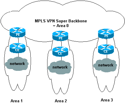
簡単な事例では、MPLS VPN スーパーバックボーンは従来のエリア 0 バックボーンと組み合わせられます。つまり、カスタマー ネットワークには、エリア 0 バックボーンはありません。これは、MPLS VPN スーパーバックボーンが、エリア 0 バックボーンと同じ役割を果たすためです。これを次の図に示します。

この図から、次のことが分かります。
-
プロバイダー エッジ(PE)ルータは、ABR および自律システム境界ルータ(ASBR)ルータです。
-
カスタマー エッジ(CE)ルータは、簡単な OSPF ルータです。
-
VPN 情報は BGP 拡張コミュニティを通じて PE から他の PE に伝送され、集約ネットワーク(タイプ 3)のリンクステート アドバタイズメント(LSA)として OSPF に再注入されます。
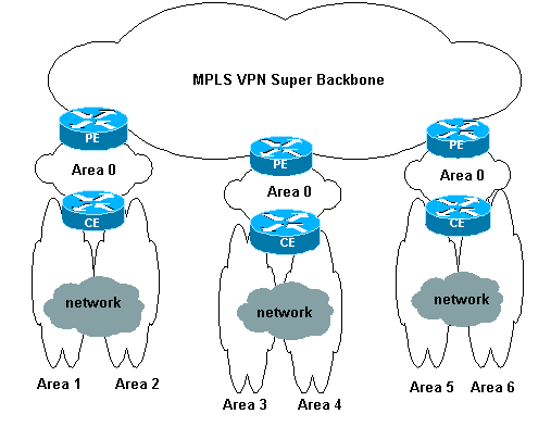
MPLS VPN スーパーバックボーンでも、カスタマーのサイトで複数のエリア 0 バックボーンを使用することができます。MPLS VPN スーパーバックボーンに接続されているかぎり、各サイトは別のエリア 0 を設定できます。分割されたエリア 0 バックボーンと結果は同じです。これを次の図に示します。

この場合は、次のようになります。
-
PE ルータは ABR および ASBR ルータです。
-
CE ルータは ABR ルータです。
-
VPN 情報を含む LSA は、BGP 拡張コミュニティを使用して PE から他の PE に伝送されます。集約ネットワーク(タイプ 3)LSA で、PE と CE 間の情報が伝送されます。
この設定例は、最初の図の設定に基づいています。ATM 経由の MPLS VPN:(カスタマー サイドの OSPF(エリア 0)による)の 2 番目の設定を使用した設定例を参照してください。
OSPF 情報は、BGP 拡張コミュニティ属性(OSPF ネットワークを識別するものを含む)付きで伝送されます。 各 VPN は固有の OSPF プロセスが必要です。この指定には、次のコマンドを使用します。
router ospf


        vrf
構成手順
このセクションでは、このドキュメントで説明する機能を設定するために必要な情報を提供しています。
注: このドキュメントで使用されているコマンドの詳細を調べるには、Command Lookup Tool(登録ユーザ専用)を使用してください。
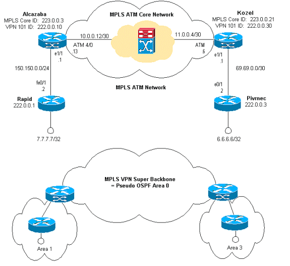
ネットワーク図
このドキュメントでは、次のネットワーク セットアップを使用します。

Cisco IOS ドキュメント(『MPLS バーチャル プライベート ネットワーク』)にも、この設定手順の説明があります。
設定手順パート I
ip cef が有効であることを確認します。Cisco 7500 ルータを使用している場合、ip cef distributed を有効にする必要があります。MPLS を設定したら、PE で次の作業を実行します。
-
ip vrf <VPN routing/forwarding instance name> コマンドを使用して、接続された各 VPN に VRF を 1 つ作成します。これを行う場合は、次の手順を実行します。
-
その VPN で使用される適切なルート区分を指定します。所属する VPN を識別できるように、IP アドレスを拡張するために使用されます。
rd -
BGP 拡張コミュニティに対し、インポート プロパティとエクスポート プロパティをセットアップします。これらは、インポートおよびエクスポート プロセスをフィルタするために使用されます。
route-target [export|import|both]
-
-
次のコマンドを使用して、各インターフェイスに対して転送の詳細を設定します。
ip vrf forwarding
この後に IP アドレスを設定することを忘れないでください。
使用している PE-CE ルーティング プロトコルに応じて、次の手順の 1 つ以上を実行する必要があります。
-
スタティック ルートの設定:
ip route vrf vrf-name prefix mask [next-hop-address] [interface {interface-number}] -
このコマンドによる RIP の設定:
address-family ipv4 vrfこの部分が終了したら、通常の RIP 設定コマンドを入力します。
注:これは、現在のVRFの転送インターフェイスにのみ適用されます。
注:正しいBGPをRIPに再配布する必要があります。これを実行する場合、使用しているメトリクスも指定することに注意してください。
-
BGP ネイバー情報を宣言します。
-
新しい IOS コマンドを使って OSPF を設定します。
router ospfvrf 注:これは、現在のVRFの転送インターフェイスにのみ適用されます。
注:正しいBGPをOSPFに再配布する必要があります。これを実行する場合、使用しているメトリクスも指定することに注意してください。
注:OSPFプロセスをVRFに属性すると、このプロセス番号が常にこの特定のVRFに使用されます。これは、コマンド ラインで VRF を指定しない場合にも当てはまります。
設定手順パート II
PE ルータ間で BGP を設定します。ルート リフレクタまたはコンフェデレーション方式を使用するように BGP を設定する方法は、いくつかあります。ここで使用する方法(直接近接設定)は、最も簡単ですが最も拡張性がありません。
-
それぞれの近接ルータを宣言します。
-
PE ルータに存在する VPN ごとに、address-family ipv4 vrf <VPN routing/forwarding instance name> コマンドを入力します。必要に応じて、次の手順を 1 つ以上を実行します。
-
スタティック ルーティング情報を再配信します。
-
RIP ルーティング情報を再配信します。
-
OSPF ルーティング情報を再配信します。
-
CE のルータで BGP ネイバーをアクティブ化します。
-
-
address-family vpnv4 mode を入力して、次のタスクを実行します。
-
近接ルータをアクティブにします。
-
拡張コミュニティを使用する必要があることを指定します。これは必須です。
-
設定
注:出力の関連する部分のみが含まれています。
Alcazaba ip cef ! ip vrf vpn1 rd 1:101 route-target export 1:101 route-target import 1:101 ! interface Loopback0 ip address 223.0.0.3 255.255.255.255 ! interface Loopback1 ip vrf forwarding vpn1 ip address 222.0.0.10 255.255.255.255 ! interface Ethernet1/1 ip vrf forwarding vpn1 ip address 150.150.0.1 255.255.255.0 no ip mroute-cache ! interface ATM4/0 no ip address no ip mroute-cache atm sonet stm-1 no atm ilmi-keepalive ! interface ATM4/0.1 tag-switching ip address 10.0.0.13 255.255.255.252 tag-switching atm vpi 2-4 tag-switching ip ! router ospf 1 log-adjacency-changes network 10.0.0.0 0.0.0.255 area 0 network 150.150.0.0 0.0.0.255 area 0 network 223.0.0.3 0.0.0.0 area 0 ! router ospf 2 vrf vpn1 log-adjacency-changes redistribute bgp 1 metric-type 1 subnets network 150.150.0.0 0.0.0.255 area 1 network 222.0.0.0 0.0.0.255 area 1 ! router bgp 1 neighbor 223.0.0.21 remote-as 1 neighbor 223.0.0.21 update-source Loopback0 ! address-family ipv4 vrf vpn1 redistribute ospf 2 no auto-summary no synchronization exit-address-family ! address-family vpnv4 neighbor 223.0.0.21 activate neighbor 223.0.0.21 send-community extended exit-address-family !
Kozel ! ip cef ! ip vrf vpn1 rd 1:101 route-target export 1:101 route-target import 1:101 ! interface Loopback0 ip address 223.0.0.21 255.255.255.255 ! interface Loopback1 ip vrf forwarding vpn1 ip address 222.0.0.30 255.255.255.255 ! interface Ethernet1/1 ip vrf forwarding vpn1 ip address 69.69.0.1 255.255.255.252 no ip mroute-cache tag-switching ip ! interface ATM4/0 no ip address no atm scrambling cell-payload no atm ilmi-keepalive pvc qsaal 0/5 qsaal ! pvc ilmi 0/16 ilmi ! ! interface ATM4/0.1 tag-switching ip address 11.0.0.6 255.255.255.252 tag-switching atm vpi 2-4 tag-switching ip ! router ospf 1 log-adjacency-changes network 11.0.0.0 0.0.0.255 area 0 network 223.0.0.21 0.0.0.0 area 0 mpls traffic-eng router-id Loopback0 mpls traffic-eng area 0 ! router ospf 2 vrf vpn1 log-adjacency-changes redistribute bgp 1 metric-type 1 subnets network 69.69.0.0 0.0.0.255 area 3 network 222.0.0.0 0.0.0.255 area 3 ! router bgp 1 neighbor 223.0.0.3 remote-as 1 neighbor 223.0.0.3 update-source Loopback0 neighbor 223.0.0.11 remote-as 1 neighbor 223.0.0.11 update-source Loopback0 ! address-family ipv4 vrf vpn1 redistribute ospf 2 no auto-summary no synchronization exit-address-family ! address-family vpnv4 neighbor 223.0.0.3 activate neighbor 223.0.0.3 send-community extended neighbor 223.0.0.11 activate neighbor 223.0.0.11 send-community extended exit-address-family !
迅速な ! interface Loopback0 ip address 222.0.0.1 255.255.255.255 ! interface Loopback2 ip address 7.7.7.7 255.255.255.0 ! interface FastEthernet0/1 ip address 150.150.0.2 255.255.255.0 duplex auto speed auto ! router ospf 1 network 7.7.7.7 0.0.0.0 area 1 network 150.150.0.0 0.0.0.255 area 1 network 222.0.0.1 0.0.0.0 area 1 !
Pivrnec ! interface Loopback0 ip address 222.0.0.3 255.255.255.255 ! interface Loopback1 ip address 6.6.6.6 255.255.255.255 ! interface FastEthernet0/1 ip address 69.69.0.2 255.255.255.252 duplex auto speed auto ! router ospf 1 log-adjacency-changes network 6.6.6.6 0.0.0.0 area 3 network 69.69.0.0 0.0.0.255 area 3 network 222.0.0.3 0.0.0.0 area 3 !
確認
show コマンド
アウトプット インタープリタ ツール(登録ユーザ専用)(OIT)は、特定の show コマンドをサポートします。OIT を使用して、show コマンドの出力の分析を表示します。
-
show ip route vrf <VPN routing or forwarding instance name>
-
show ip bgp vpnv4 vrf <VPN routing or forwarding instance name> <A.B.C.D>
-
show ip ospf <process ID number>
-
show ip ospf <process ID number> interface
-
show ip ospf <process ID number> database
-
show tag-switching forwarding-table vrf <VPN routing or forwarding instance name>
PE ルータで特定 VPN の VRF を表示するコマンドの例:
Alcazaba#show ip route vrf vpn1
Codes: C - connected, S - static, I - IGRP, R - RIP, M - mobile, B - BGP
       D - EIGRP, EX - EIGRP external, O - OSPF, IA - OSPF inter area
       N1 - OSPF NSSA external type 1, N2 - OSPF NSSA external type 2
       E1 - OSPF external type 1, E2 - OSPF external type 2, E - EGP
       i - IS-IS, L1 - IS-IS level-1, L2 - IS-IS level-2, ia - IS-IS inter area
       * - candidate default, U - per-user static route, o - ODR
       P - periodic downloaded static route

Gateway of last resort is not set

     69.0.0.0/30 is subnetted, 1 subnets
B       69.69.0.0 [200/0] via 223.0.0.21, 00:19:39
     222.0.0.0/32 is subnetted, 4 subnets
B       222.0.0.30 [200/0] via 223.0.0.21, 00:19:39
C       222.0.0.10 is directly connected, Loopback1
B       222.0.0.3 [200/11] via 223.0.0.21, 00:20:39
O       222.0.0.1 [110/11] via 150.150.0.2, 00:20:59, Ethernet1/1
     6.0.0.0/32 is subnetted, 1 subnets
B       6.6.6.6 [200/11] via 223.0.0.21, 00:20:39
     7.0.0.0/32 is subnetted, 1 subnets
O       7.7.7.7 [110/11] via 150.150.0.2, 00:21:00, Ethernet1/1
     150.150.0.0/24 is subnetted, 1 subnets
C       150.150.0.0 is directly connected, Ethernet1/1
show ip bgp vpnv4 vrf コマンドを使用して、特定 VRF の BGP 情報を表示することができます。内部 BGP(IBGP)からの PE-PE は、i によって示されます。
Alcazaba#show ip bgp vpnv4 vrf vpn1
BGP table version is 21, local router ID is 223.0.0.3
Status codes: s suppressed, d damped, h history, * valid, > best, i - internal
Origin codes: i - IGP, e - EGP, ? - incomplete

   Network          Next Hop            Metric LocPrf Weight Path
Route Distinguisher: 1:101 (default for vrf vpn1)
*>i6.6.6.6/32       223.0.0.21              11    100      0 ?
*> 7.7.7.7/32       150.150.0.2             11         32768 ?
*>i69.69.0.0/30     223.0.0.21               0    100      0 ?
*> 150.150.0.0/24   0.0.0.0                  0         32768 ?
*> 222.0.0.1/32     150.150.0.2             11         32768 ?
*>i222.0.0.3/32     223.0.0.21              11    100      0 ?
*> 222.0.0.10/32    0.0.0.0                  0         32768 ?
*>i222.0.0.30/32    223.0.0.21               0    100      0 ?
エントリの詳細は確認することができます。これを表示するためのルート識別子は「1:101」です。
Alcazaba#show ip bgp vpnv4 vrf vpn1 6.6.6.6
BGP routing table entry for 1:101:6.6.6.6/32, version 28
Paths: (1 available, best #1, table vpn1)
  Not advertised to any peer
  Local
    223.0.0.21 (metric 4) from 223.0.0.21 (223.0.0.21)
      Origin incomplete, metric 11, localpref 100, valid, internal, best
      Extended Community: RT:1:101 OSPF RT:3:2:0

Alcazaba#show ip bgp vpnv4 vrf vpn1 7.7.7.7
BGP routing table entry for 1:101:7.7.7.7/32, version 20
Paths: (1 available, best #1, table vpn1)
  Advertised to non peer-group peers:
  223.0.0.21
  Local
    150.150.0.2 from 0.0.0.0 (223.0.0.3)
      Origin incomplete, metric 11, localpref 100, weight 32768, valid, sourced, best
      Extended Community: RT:1:101 OSPF RT:1:2:0
CE ルータの show ip route コマンドは、ルーティング テーブルを確認するための主要な方法です。
rapid#show ip route
Codes: C - connected, S - static, I - IGRP, R - RIP, M - mobile, B - BGP
       D - EIGRP, EX - EIGRP external, O - OSPF, IA - OSPF inter area
       N1 - OSPF NSSA external type 1, N2 - OSPF NSSA external type 2
       E1 - OSPF external type 1, E2 - OSPF external type 2, E - EGP
       i - IS-IS, L1 - IS-IS level-1, L2 - IS-IS level-2, ia - IS-IS inter area
       * - candidate default, U - per-user static route, o - ODR
       P - periodic downloaded static route

Gateway of last resort is not set

     69.0.0.0/30 is subnetted, 1 subnets
O IA    69.69.0.0 [110/11] via 150.150.0.1, 00:20:25, FastEthernet0/1
     222.0.0.0/32 is subnetted, 4 subnets
O IA    222.0.0.30 [110/11] via 150.150.0.1, 00:20:25, FastEthernet0/1
O       222.0.0.10 [110/11] via 150.150.0.1, 00:21:46, FastEthernet0/1
O IA    222.0.0.3 [110/21] via 150.150.0.1, 00:21:25, FastEthernet0/1
C       222.0.0.1 is directly connected, Loopback0
     6.0.0.0/32 is subnetted, 1 subnets
O IA    6.6.6.6 [110/21] via 150.150.0.1, 00:21:25, FastEthernet0/1
     7.0.0.0/24 is subnetted, 1 subnets
C       7.7.7.0 is directly connected, Loopback2
     10.0.0.0/22 is subnetted, 1 subnets
C       10.200.8.0 is directly connected, FastEthernet0/0
     150.150.0.0/24 is subnetted, 1 subnets
C       150.150.0.0 is directly connected, FastEthernet0/1
S    158.0.0.0/8 is directly connected, Null0
OSPF 特有のコマンド
すべての show ip ospf コマンドが使用できます。これを実行する場合、プロセス ID を示すことを忘れないでください。次の出力のイタリック体のテキストの最も重要な部分にマークを付けてあります。
トラフィックの設計には、タイプ 9、10、11 の OSPF LSA(別名 Opaque LSA)が使用されます。
PE ルータ用コマンド
Alcazaba#show ip ospf 2
 Routing Process "ospf 2" with ID 222.0.0.10
 Supports only single TOS(TOS0) routes
 Supports opaque LSA
 Connected to MPLS VPN super backbone
 It is an area border and autonomous system boundary router
 Redistributing External Routes from,
    bgp 1, includes subnets in redistribution
 SPF schedule delay 5 secs, Hold time between two SPFs 10 secs
 Minimum LSA interval 5 secs. Minimum LSA arrival 1 secs
 Number of external LSA 0. Checksum Sum 0x0
 Number of opaque AS LSA 0. Checksum Sum 0x0
 Number of DCbitless external and opaque AS LSA 0
 Number of DoNotAge external and opaque AS LSA 0
 Number of areas in this router is 1. 1 normal 0 stub 0 nssa
 External flood list length 0
    Area 1
        Number of interfaces in this area is 2
        Area has no authentication
        SPF algorithm executed 4 times
        Area ranges are
        Number of LSA 7. Checksum Sum 0x420BE
        Number of opaque link LSA 0. Checksum Sum 0x0
        Number of DCbitless LSA 0
        Number of indication LSA 0
        Number of DoNotAge LSA 0
        Flood list length 0

Alcazaba#show ip ospf 2 interface
Loopback1 is up, line protocol is up
  Internet Address 222.0.0.10/32, Area 1
  Process ID 2, Router ID 222.0.0.10, Network Type LOOPBACK, Cost: 1
  Loopback interface is treated as a stub Host
Ethernet1/1 is up, line protocol is up
  Internet Address 150.150.0.1/24, Area 1
  Process ID 2, Router ID 222.0.0.10, Network Type BROADCAST, Cost: 10
  Transmit Delay is 1 sec, State DR, Priority 1
  Designated Router (ID) 222.0.0.10, Interface address 150.150.0.1
  Backup Designated router (ID) 222.0.0.1, Interface address 150.150.0.2
  Timer intervals configured, Hello 10, Dead 40, Wait 40, Retransmit 5
    Hello due in 00:00:07
  Index 1/1, flood queue length 0
  Next 0x0(0)/0x0(0)
  Last flood scan length is 2, maximum is 3
  Last flood scan time is 0 msec, maximum is 0 msec
  Neighbor Count is 1, Adjacent neighbor count is 1
    Adjacent with neighbor 222.0.0.1  (Backup Designated Router)
  Suppress hello for 0 neighbor(s)

Alcazaba#show ip ospf 2 database

            OSPF Router with ID (222.0.0.10) (Process ID 2)

                Router Link States (Area 1)

Link ID         ADV Router      Age         Seq#       Checksum Link count
222.0.0.1       222.0.0.1       1364        0x80000013 0x7369   3
222.0.0.10      222.0.0.10      1363        0x80000002 0xFEFE   2

                Net Link States (Area 1)

Link ID         ADV Router      Age         Seq#       Checksum
150.150.0.1     222.0.0.10      1363        0x80000001 0xEC6D

                Summary Net Link States (Area 1)

Link ID         ADV Router      Age         Seq#       Checksum
6.6.6.6         222.0.0.10      1328        0x80000001 0x4967
69.69.0.0       222.0.0.10      1268        0x80000001 0x2427
222.0.0.3       222.0.0.10      1328        0x80000001 0xEEF7
222.0.0.30      222.0.0.10      1268        0x80000001 0x7B5A
CE ルータ用コマンド
rapid#show ip ospf interface
FastEthernet0/1 is up, line protocol is up
  Internet Address 150.150.0.2/24, Area 1
  Process ID 1, Router ID 222.0.0.1, Network Type BROADCAST, Cost: 10
  Transmit Delay is 1 sec, State BDR, Priority 1
  Designated Router (ID) 222.0.0.10, Interface address 150.150.0.1
  Backup Designated router (ID) 222.0.0.1, Interface address 150.150.0.2
  Timer intervals configured, Hello 10, Dead 40, Wait 40, Retransmit 5
    Hello due in 00:00:04
  Index 2/2, flood queue length 0
  Next 0x0(0)/0x0(0)
  Last flood scan length is 1, maximum is 2
  Last flood scan time is 0 msec, maximum is 0 msec
  Neighbor Count is 1, Adjacent neighbor count is 1
    Adjacent with neighbor 222.0.0.10  (Designated Router)
  Suppress hello for 0 neighbor(s)
Loopback0 is up, line protocol is up
  Internet Address 222.0.0.1/32, Area 1
  Process ID 1, Router ID 222.0.0.1, Network Type LOOPBACK, Cost: 1
  Loopback interface is treated as a stub Host
Loopback2 is up, line protocol is up
  Internet Address 7.7.7.7/24, Area 1
  Process ID 1, Router ID 222.0.0.1, Network Type LOOPBACK, Cost: 1
  Loopback interface is treated as a stub Host

rapid#show ip ospf database

       OSPF Router with ID (222.0.0.1) (Process ID 1)

                Router Link States (Area 1)

Link ID         ADV Router      Age         Seq#       Checksum Link count
222.0.0.1       222.0.0.1       1350        0x80000013 0x7369   3
222.0.0.10      222.0.0.10      1350        0x80000002 0xFEFE   2

                Net Link States (Area 1)

Link ID         ADV Router      Age         Seq#       Checksum
150.150.0.1     222.0.0.10      1351        0x80000001 0xEC6D

                Summary Net Link States (Area 1)

Link ID         ADV Router      Age         Seq#       Checksum
6.6.6.6         222.0.0.10      1316        0x80000001 0x4967
69.69.0.0       222.0.0.10      1256        0x80000001 0x2427
222.0.0.3       222.0.0.10      1316        0x80000001 0xEEF7
222.0.0.30      222.0.0.10      1256        0x80000001 0x7B5A

Alcazaba#show tag-switching forwarding-table vrf vpn1
Local  Outgoing    Prefix            Bytes tag  Outgoing   Next Hop
tag    tag or VC   or Tunnel Id      switched   interface
24     Aggregate   222.0.0.10/32[V]  0
25     Aggregate   150.150.0.0/24[V] 0
27     Untagged    7.7.7.7/32[V]     1710       Et1/1      150.150.0.2
28     Untagged    222.0.0.1/32[V]   0          Et1/1      150.150.0.2
MPLS ラベル
特定のルートに対して使用されるラベル スタックをチェックします:
Alcazaba#show tag-switching forwarding-table vrf vpn1 6.6.6.6 detail
Local  Outgoing    Prefix            Bytes tag  Outgoing   Next Hop
tag    tag or VC   or Tunnel Id      switched   interface
None   2/41        6.6.6.6/32        0          AT4/0.1    point2point
        MAC/Encaps=4/12, MTU=4466, Tag Stack{2/41(vcd=10) 16}
        000A8847 0000A00000010000
Debugging Output
ルート交換のデバッグ情報からの抜粋を次に示します。これは、特定のルートのインポート方法を示しています。
Alcazaba#debug ip bgp vpnv4 import
Tag VPN import processing debugging is on
*Aug  5 05:10:09.283: vpn: Start import processing for: 1:101:222.0.0.3
*Aug  5 05:10:09.283: vpn: Import check for vpn1; flags mtch, impt
*Aug  5 05:10:09.283: vpn: Import for vpn1 permitted; import flags mtch, impt
*Aug  5 05:10:09.283: vpn: Same RD import for vpn1
*Aug  5 05:10:09.283: vpn: 1:101:222.0.0.3 (ver 29), imported as:
*Aug  5 05:10:09.283: vpn: 1:101:222.0.0.3 (ver 29)
*Aug  5 05:10:09.287: VPN: Scanning for import check is done.
テスト出力
すべてが正しく機能していることをテストするには、ping を使用します。
Pivrnec#ping 7.7.7.7

Type escape sequence to abort.
Sending 5, 100-byte ICMP Echos to 7.7.7.7, timeout is 2 seconds:
!!!!!
Success rate is 100 percent (5/5), round-trip min/avg/max = 1/2/4 ms
traceroute コマンドは、次の出力を表示します。
Pivrnec#traceroute 7.7.7.7

Type escape sequence to abort.
Tracing the route to 7.7.7.7

  1 69.69.0.1 0 msec 0 msec 0 msec
  2 150.150.0.1 0 msec 0 msec 20 msec
  3 150.150.0.2 0 msec 0 msec *
IP ヘッダーが表示されないため、MLPS ホストはここにはありません。MPLS ホストは、インバウンド ラベルまたはインターフェイスのみを確認して、転送します。
IP Time To Live(TTL)フィールドの操作は、エッジ LSR でのみ実行されます。次のホップ カウントは実際のホップ カウントを下回っています。
関連情報
更新履歴
| 改定 | 発行日 | コメント |
|---|---|---|
1.0 |
05-Jun-2005 |
初版 |
 フィードバック