ASA/PIX:CLIおよびASDMを使用したIPSec VPNクライアントのスタティックIPアドレスの設定例
内容
はじめに
このドキュメントでは、Adaptive Security Device Manager(ASDM)または CLI を使用してスタティック IP アドレスを VPN Client に提供できるよう Cisco 5500 シリーズ Adaptive Security Appliance(ASA; 適応型セキュリティ アプライアンス)を設定する方法について解説します。ASDM では、直感的で使用が容易な Web ベースの管理インターフェイスにより、ワールドクラスのセキュリティ管理とモニタリング機能が提供されています。Cisco ASA の設定が完了すると、Cisco VPN Client を使用して、これを確認できます。
Cisco VPN Client(4.x for Windows)と PIX 500 シリーズ セキュリティ アプライアンス 7.x との間にリモート アクセス VPN 接続を設定する方法については、「PIX/ASA 7.x および Cisco VPN Client 4.x で Active Directory に対する Windows 2003 IAS RADIUS 認証を使用するための設定例」を参照してください。リモートの VPN Client ユーザは Microsoft Windows 2003 Internet Authentication Service(IAS)RADIUS サーバを使用して Active Directory に対する認証を行います。
Cisco Secure Access Control Server(ACS バージョン 3.2)を使用して拡張認証(Xauth)用に、Cisco VPN Client(4.x for Windows)と PIX 500 シリーズ セキュリティ アプライアンス 7.x との間にリモート アクセス VPN 接続を設定する方法については、『PIX/ASA 7.x と Cisco VPN Client 4.x の Cisco Secure ACS 認証用の設定例』を参照してください。
前提条件
要件
このドキュメントでは、ASA が完全に動作していて、Cisco ASDM または CLI で設定を変更できるように設定されていることを想定しています。
注:ASDMまたはSecure Shell(SSH)でデバイスをリモートから設定できるようにする方法については、『ASDM用のHTTPSアクセスの許可』または『InsideおよびOutsideインターフェイスでのPIX/ASA 7.x:SSHの設定例』を参照してください。
使用するコンポーネント
このドキュメントの情報は、次のソフトウェアとハードウェアのバージョンに基づいています。
-
Cisco 適応型セキュリティ アプライアンス ソフトウェア バージョン 7.x 以降
-
Adaptive Security Device Manager バージョン 5.x 以降
-
Cisco VPN Client バージョン 4.x 以降
このドキュメントの情報は、特定のラボ環境にあるデバイスに基づいて作成されました。このドキュメントで使用するすべてのデバイスは、クリアな(デフォルト)設定で作業を開始しています。対象のネットワークが実稼働中である場合には、どのようなコマンドについても、その潜在的な影響について確実に理解しておく必要があります。
関連製品
この設定は、Cisco PIX セキュリティ アプライアンス バージョン 7.x 以降にも適用できます。
表記法
表記法の詳細については、『シスコ テクニカル ティップスの表記法』を参照してください。
設定
このセクションでは、このドキュメントで説明する機能を設定するために必要な情報を提供しています。
注:このセクションで使用されているコマンドの詳細を調べるには、Command Lookup Tool(登録ユーザ専用)を使用してください。
ネットワーク図
このドキュメントでは、次のネットワーク セットアップを使用します。
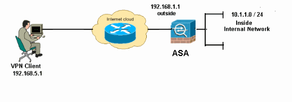
注:この設定で使用されているIPアドレッシング方式は、インターネット上で正式にルーティング可能なものではありません。これらは RFC 1918 でのアドレスであり、ラボ環境で使用されたものです。
リモート アクセス VPN(IPsec)の設定
ASDM の手順
リモート アクセス VPN を設定するには、次の手順を実行します。
-
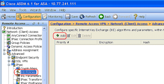
[Configuration] > [Remote Access VPN] > [Network (Client) Access] > [Advanced] > [IPSec] > [IKE Policies] > [Add] を選択し、ISAKMP ポリシーを作成します。
-
ISAKMP ポリシーの詳細情報を設定します。
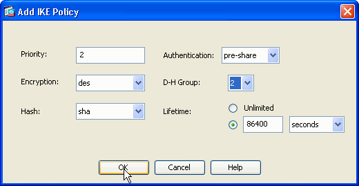
[OK] および [Apply] をクリックします。
-
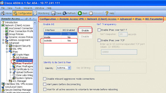
[Configuration] > [Remote Access VPN] > [Network (Client) Access] > [Advanced] > [IPSec] > [IKE Parameters] を選択し、外部インターフェイス上の IKE を有効にします。
-
[Configuration] > [Remote Access VPN] > [Network (Client) Access] > [Advanced] > [IPSec] > [IPSec Transform Sets] > [Add] の順に選択し、次のように ESP-DES-SHA トランスフォームを作成します。
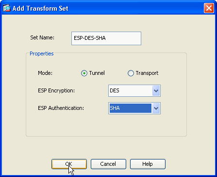
[OK] および [Apply] をクリックします。
-
[Configuration] > [Remote Access VPN] > [Network (Client) Access] > [Advanced] > [IPSec] > [Crypto Maps] > [Add] の順に選択し、次のような Priority 1 のダイナミック ポリシーを持つ暗号マップを作成します。
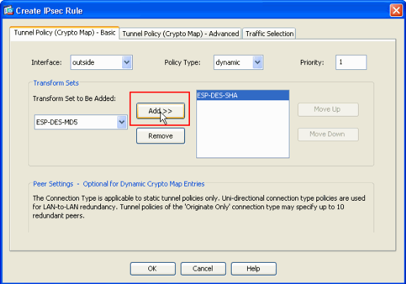
[OK] および [Apply] をクリックします。
-
[Configuration] > [Remote Access VPN] > [AAA Setup] > [Local Users] > [Add] の順に選択し、VPN Client アクセス用のユーザ アカウント(例:Username - cisco123、Password - cisco123)を作成します。
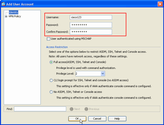
-
[VPN Policy] に移動し、次のようにユーザ "cisco123" の Static/Dedicated IP Address を追加します。
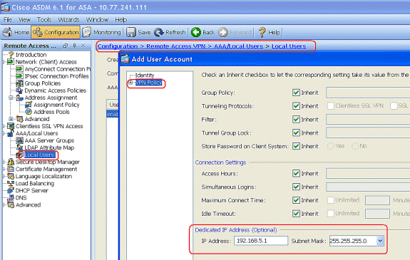
-
[Configuration] > [Remote Access VPN] > [Network (Client) Access] > [Address Assignment] > [Address Pools] を選択して [Add] をクリックし、VPN Client ユーザの VPN Client を追加します。
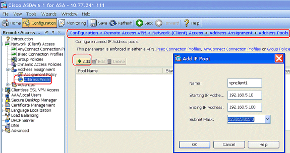
-
[Configuration] > [Remote Access VPN] > [Network (Client) Access] > [IPSec Connection Profiles] > [Add] を選択し、次のようにトンネル グループ(例:TunnelGroup1、事前共有鍵が cisco123)を追加します。
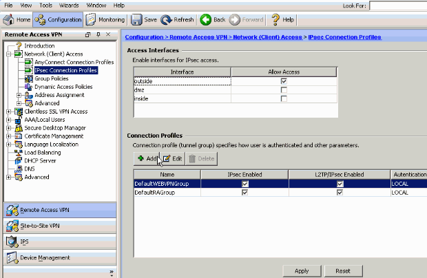
-
[Basic] タブの User Authentication フィールドで、サーバ グループとして LOCAL を選択します。
-
VPN Client ユーザの Client Address Pools として vpnclient1 を選択します。
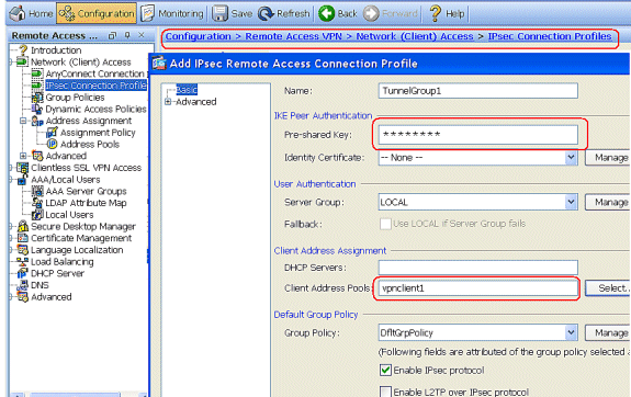
[OK] をクリックします。
-
-
[Advanced] > [Client Addressing] を選択し、[Use address pool] チェック ボックスにチェックマークを入れて、VPN Client に IP アドレスを割り当てます。
注:Use authentication serverとUse DHCPのチェックボックスをオフにしてください。
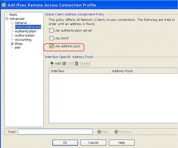
[OK] をクリックします。
-
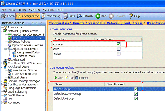
IPSec アクセスの [outside] インターフェイスを有効にします。[Apply] をクリックして続行します。
CLI による ASA/PIX の設定
後述のステップを実行して DHCP サーバを設定し、コマンドラインから VPN Client に IP アドレスを割り当てます。使用する各コマンドについての詳細は、リモート アクセス VPN の設定または『Cisco ASA 5500 シリーズ適応型セキュリティ アプライアンス コマンド リファレンス』を参照してください。
| ASA デバイスでの実行コンフィギュレーション |
|---|
ASA# sh run ASA Version 8.0(2) ! !--- Specify the hostname for the Security Appliance. hostname ASA enable password 8Ry2YjIyt7RRXU24 encrypted names ! !--- Configure the outside and inside interfaces. interface Ethernet0/0 nameif inside security-level 100 ip address 10.1.1.1 255.255.255.0 ! interface Ethernet0/1 nameif outside security-level 0 ip address 192.168.1.1 255.255.255.0 ! interface Ethernet0/2 nameif DMZ security-level 50 ip address 192.168.10.2 255.255.255.0 !--- Output is suppressed. passwd 2KFQnbNIdI.2KYOU encrypted boot system disk0:/asa802-k8.bin ftp mode passive access-list 101 extended permit ip 10.1.1.0 255.255.255.0 192.168.5.0 255.255.255.0 pager lines 24 logging enable logging asdm informational mtu inside 1500 mtu outside 1500 mtu dmz 1500 ip local pool vpnclient1 192.168.5.10-192.168.5.100 mask 255.255.255.0 no failover icmp unreachable rate-limit 1 burst-size 1 !--- Specify the location of the ASDM image for ASA to fetch the image for ASDM access. asdm image disk0:/asdm-613.bin no asdm history enable arp timeout 14400 global (outside) 1 192.168.1.5 nat (inside) 0 access-list 101 nat (inside) 1 0.0.0.0 0.0.0.0 route outside 0.0.0.0 0.0.0.0 192.168.1.2 1 timeout xlate 3:00:00 timeout conn 1:00:00 half-closed 0:10:00 udp 0:02:00 icmp 0:00:02 timeout sunrpc 0:10:00 h323 0:05:00 h225 1:00:00 mgcp 0:05:00 mgcp-pat 0:05:00 timeout sip 0:30:00 sip_media 0:02:00 sip-invite 0:03:00 sip-disconnect 0:02:00 timeout uauth 0:05:00 absolute dynamic-access-policy-record DfltAccessPolicy http server enable http 0.0.0.0 0.0.0.0 inside no snmp-server location no snmp-server contact snmp-server enable traps snmp authentication linkup linkdown coldstart crypto ipsec transform-set ESP-DES-SHA esp-des esp-sha-hmac crypto dynamic-map outside_dyn_map 1 set transform-set ESP-DES-SHA crypto map outside_map 1 ipsec-isakmp dynamic outside_dyn_map !--- Specifies the interface to be used with !--- the settings defined in this configuration. crypto map outside_map interface outside !--- PHASE 1 CONFIGURATION ---! !--- This configuration uses ISAKMP policy 2. !--- The configuration commands here define the Phase !--- 1 policy parameters that are used. crypto isakmp enable outside crypto isakmp policy 2 authentication pre-share encryption des hash sha group 2 lifetime 86400 no crypto isakmp nat-traversal !--- Specifies that the IP address to the vpn clients are assigned by the local and not by AAA or dhcp. The CLI vpn-addr-assign local for VPN address assignment through ASA is hidden in the CLI provided by show run command. no vpn-addr-assign aaa no vpn-addr-assign dhcp telnet timeout 5 ssh timeout 5 console timeout 0 threat-detection basic-threat threat-detection statistics access-list ! class-map inspection_default match default-inspection-traffic ! ! policy-map type inspect dns preset_dns_map parameters message-length maximum 512 policy-map global_policy class inspection_default inspect dns preset_dns_map inspect ftp inspect h323 h225 inspect h323 ras inspect netbios inspect rsh inspect rtsp inspect skinny inspect esmtp inspect sqlnet inspect sunrpc inspect tftp inspect sip inspect xdmcp ! service-policy global_policy global ! group-policy DfltGrpPolicy attributes vpn-tunnel-protocol IPSec webvpn group-policy GroupPolicy1 internal !--- In order to identify remote access users to the Security Appliance, !--- you can also configure usernames and passwords on the device. !--- specify the IP address to assign to a particular user, use the vpn-framed-ip-address command !--- in username mode username cisco123 password ffIRPGpDSOJh9YLq encrypted username cisco123 attributes vpn-framed-ip-address 192.168.5.1 255.255.255.0 !--- Create a new tunnel group and set the connection !--- type to remote-access. tunnel-group TunnelGroup1 type remote-access tunnel-group TunnelGroup1 general-attributes address-pool vpnclient1 !--- Enter the pre-shared-key to configure the authentication method. tunnel-group TunnelGroup1 ipsec-attributes pre-shared-key * prompt hostname context Cryptochecksum:e0725ca9ccc28af488ded9ee36b7822d : end ASA# |
Cisco VPN Client の設定
ASA の設定に成功したことを確認するには、Cisco VPN Client を使用して Cisco ASA に接続してみます。
-
[Start] > [Programs] > [Cisco Systems VPN Client] > [VPN Client] の順に選択します。
-
[New] をクリックして、[Create New VPN Connection Entry] ウィンドウを開きます。

-
新しい接続の詳細情報を入力します。
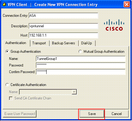
接続エントリの名前と説明を入力します。Host ボックスに、ASA の Outside の IP アドレスを入力します。次に、ASAで設定したVPNトンネルグループ名(TunnelGroup1)とパスワード(事前共有キー – cisco123)を入力します。[Save] をクリックします。
-
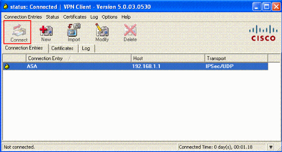
使用する接続をクリックし、VPN Client メイン ウィンドウの [Connect] をクリックします。
-
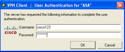
プロンプトが表示されたら、Xauth用のASAで設定されているようにユーザ名:cisco123とパスワード:cisco123を入力し、OKをクリックしてリモートネットワークに接続します。
-
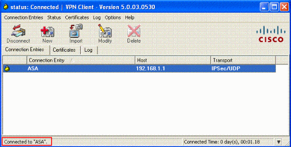
VPN Client が中央サイトの ASA に接続されます。
-
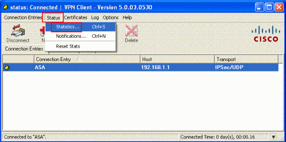
接続が正常に確立されたら、[Status] メニューから [Statistics] を選択し、トンネルの詳細情報を検証します。
確認
show コマンド
このセクションでは、設定が正常に動作していることを確認します。
Output Interpreter Tool(OIT)(登録ユーザ専用)では、特定の show コマンドがサポートされています。OIT を使用して show コマンド出力の解析を表示します。
-
show crypto isakmp sa:ピアにおける現在の IKE セキュリティ アソシエーション(SA)をすべて表示します。
-
show crypto ipsec sa:現在の SA が使用している設定を表示します。
トラブルシュート
このセクションでは、設定のトラブルシューティングに役立つ情報を紹介します。デバッグ出力例も紹介しています。
注:リモートアクセスIPSec VPNの詳細は、『一般的なL2LおよびリモートアクセスIPSec VPNのトラブルシューティング方法について』を参照してください。
セキュリティ アソシエーションのクリア
トラブルシューティングを行う際には、変更を加えた後、既存のセキュリティ アソシエーションを必ずクリアしてください。PIX の特権モードで、次のコマンドを使用します。
-
clear [crypto] ipsec sa:アクティブな IPSec SA を削除します。crypto キーワードはオプションです。
-
clear [crypto] isakmp sa:アクティブな IKE SA を削除します。crypto キーワードはオプションです。
トラブルシューティングのためのコマンド
Output Interpreter Tool(OIT)(登録ユーザ専用)では、特定の show コマンドがサポートされています。OIT を使用して show コマンド出力の解析を表示します。
注:debug コマンドを使用する前に、『debug コマンドの重要な情報』を参照してください。
-
debug crypto ipsec 7:フェーズ 2 の IPSec ネゴシエーションを表示します。
-
debug crypto isakmp 7:フェーズ 1 の ISAKMP ネゴシエーションを表示します。
関連情報
- Cisco ASA 5500 シリーズ適応型セキュリティ アプライアンスに関するサポート ページ
- Cisco ASA 5500 シリーズ適応型セキュリティ アプライアンス、コマンド リファレンス
- Cisco PIX 500 シリーズ セキュリティ アプライアンス サポート ページ
- Cisco PIX 500 シリーズ セキュリティ アプライアンス、コマンド リファレンス
- Cisco Adaptive Security Device Manager
- IPSec ネゴシエーション/IKE プロトコルに関するサポート ページ
- Cisco VPN Client に関するサポート ページ
- Cisco PIX Firewall ソフトウェア
- Cisco Secure PIX ファイアウォール コマンド リファレンス
- セキュリティ製品に関する Field Notice(PIX を含む)
- Requests for Comments (RFCs)

- テクニカル サポートとドキュメント - Cisco Systems
更新履歴
| 改定 | 発行日 | コメント |
|---|---|---|
1.0 |
16-Feb-2009 |
初版 |
 フィードバック