ACIマルチサイトファブリックによるサイト間L3outの設定
ダウンロード オプション
偏向のない言語
この製品のドキュメントセットは、偏向のない言語を使用するように配慮されています。このドキュメントセットでの偏向のない言語とは、年齢、障害、性別、人種的アイデンティティ、民族的アイデンティティ、性的指向、社会経済的地位、およびインターセクショナリティに基づく差別を意味しない言語として定義されています。製品ソフトウェアのユーザインターフェイスにハードコードされている言語、RFP のドキュメントに基づいて使用されている言語、または参照されているサードパーティ製品で使用されている言語によりドキュメントに例外が存在する場合があります。シスコのインクルーシブ ランゲージの取り組みの詳細は、こちらをご覧ください。
翻訳について
シスコは世界中のユーザにそれぞれの言語でサポート コンテンツを提供するために、機械と人による翻訳を組み合わせて、本ドキュメントを翻訳しています。ただし、最高度の機械翻訳であっても、専門家による翻訳のような正確性は確保されません。シスコは、これら翻訳の正確性について法的責任を負いません。原典である英語版(リンクからアクセス可能)もあわせて参照することを推奨します。
内容
概要
このドキュメントでは、Cisco Application Centric Infrastructure(ACI)マルチサイトファブリックを使用したサイト間L3out設定の手順について説明します。
前提条件
要件
次の項目に関する知識があることが推奨されます。
- ACIマルチサイトファブリックの機能設定
- 外部ルータ/接続
使用するコンポーネント
このドキュメントの情報は、次のハードウェアに基づくものです。
-
Multi-Site Orchestrator(MSO)バージョン2.2(1)以降
-
ACIバージョン4.2(1)以降
- MSOノード
- ACIファブリック
- Nexus 9000シリーズスイッチ(N9K)(エンドホストおよびL3out外部デバイスシミュレーション)
- Nexus 9000シリーズスイッチ(N9K)(サイト間ネットワーク(ISN))
このドキュメントの情報は、特定のラボ環境にあるデバイスに基づいて作成されました。このドキュメントで使用するすべてのデバイスは、初期(デフォルト)設定の状態から起動しています。本稼働中のネットワークでは、各コマンドによって起こる可能性がある影響を十分確認してください。
背景説明
サイト間L3out設定でサポートされるスキーマ
Schema-config1
- サイト間でテナントを拡張(AとB)。
- サイト(AとB)間で拡張される仮想ルーティングおよび転送(VRF)。
- 1つのサイト(A)に対してローカルなエンドポイントグループ(EPG)/ブリッジドメイン(BD)。
- 別のサイトにローカルなL3out(B)。
- L3outの外部EPG(ローカルからサイト(B))。
- 契約の作成と設定はMSOから行われます。
Schema-config2
- サイト間でテナントを拡張(AとB)。
- サイト間に拡張されたVRF(AとB)。
- サイト間でEPG/BDを拡張(AとB)。
- 1つのサイトに対するL3out(B)。
- L3outの外部EPG(ローカルからサイト(B))。
- 契約の設定はMSOから行うか、各サイトでApplication Policy Infrastructure Controller(APIC)からローカル契約が作成され、拡張されたEPGとL3out外部EPGの間にローカルに接続されます。この場合、シャドウExternal_EPGはローカルの契約関係とポリシーの実装に必要なため、サイトAに表示されます。
Schema-config3
- サイト間でテナントを拡張(AとB)。
- サイト間に拡張されたVRF(AとB)。
- サイト間でEPG/BDを拡張(AとB)。
- 1つのサイトに対するL3out(B)。
- サイト間に拡張されたL3outの外部EPG(AおよびB)。
- 契約の設定はMSOから実行できます。また、各サイトでAPICからローカル契約が作成され、拡張されたEPGと拡張された外部EPGの間にローカルに接続されます。
Schema-config4
- サイト間でテナントを拡張(AとB)。
- サイト間に拡張されたVRF(AとB)。
- EPG/BDは1つのサイト(A)にローカル、またはEPG/BDは各サイトにローカル(サイトAではEPG-A、サイトBではEPG-B)。
- L3out local to one site(B)、または外部接続に対する冗長性のために、L3outを各サイト(ローカルからサイトA、ローカルからサイトB)にローカルにできます。
- サイト間に拡張されたL3outの外部EPG(AおよびB)。
- 契約の設定はMSOから行うことも、各サイトがAPICからローカル契約を作成し、拡張EPGと拡張された外部EPGの間にローカルに接続することもできます。
Schema-config5(中継ルーティング)
- サイト間でテナントを拡張(AとB)。
- サイト間に拡張されたVRF(AとB)。
- 各サイトにローカルなL3out(ローカルからサイトA、ローカルからサイトB)。
- 各サイト(AおよびB)に対するローカルの外部EPG。
- 契約の設定はMSOから行うことも、各サイトでAPICからローカル契約を作成し、外部EPGローカルとシャドウ外部EPGローカルの間にローカルに接続することもできます。
Schema-config5(InterVRFトランジットルーティング)
- サイト間でテナントを拡張(AとB)。
- 各サイト(AおよびB)に対してローカルなVRF。
- 各サイトにローカルなL3out(ローカルからサイトA、ローカルからサイトB)。
- 各サイト(AおよびB)に対するローカルの外部EPG。
- 契約の設定はMSOから行うことも、各サイトでAPICからローカル契約を作成し、外部EPGローカルとシャドウ外部EPGローカルの間にローカルに接続することもできます。
注:このドキュメントでは、基本的なサイト間L3out設定手順と検証について説明します。この例では、Schema-config1が使用されています。
設定
ネットワーク図
物理トポロジ

論理トポロジ
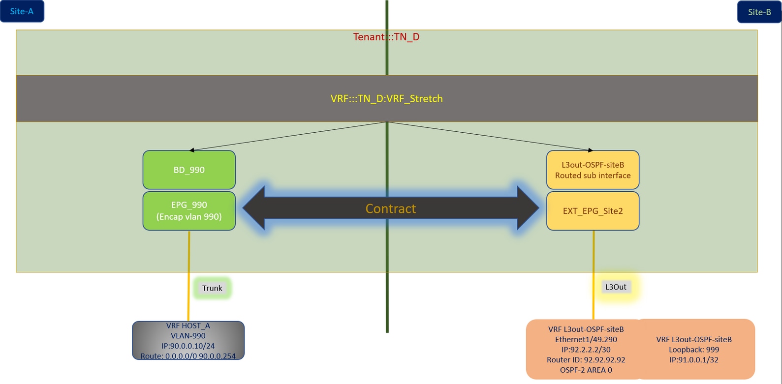
設定
この例では、Schema-config1を使用します。ただし、サポートされている他のスキーマ構成に対しても、この構成は同じように(契約関係に応じた小さな変更で)完了できます。ただし、拡張オブジェクトは、特定のサイト・テンプレートではなく、拡張テンプレートに含める必要があります。
Schema-config1の設定
- サイト間でテナントを拡張(AとB)。
- サイト間に拡張されたVRF(AとB)。
- EPG/BDは1つのサイトにローカル(A)。
- 別のサイトにローカルなL3out(B)。
- L3outの外部EPG(ローカルからサイト(B))。
- 契約の作成と構成はMSOから行われます。
サイト間L3Outのガイドラインと制限事項を確認します。
-
サイト間L3outでサポートされていない設定:
-
別のサイトL3out経由で外部ソースからマルチキャストを受信するサイトのマルチキャスト受信者。外部ソースからサイトで受信したマルチキャストは、他のサイトには送信されません。サイト内のレシーバが外部ソースからマルチキャストを受信する場合、ローカルL3outでマルチキャストを受信する必要があります。
-
内部マルチキャストソースは、PIM-SM any source multicast(ASM)を使用して外部レシーバにマルチキャストを送信します。 内部マルチキャストソースは、ローカルL3outから外部ランデブーポイント(RP)に到達できる必要があります。
-
Giant OverLay Fabric(GOLF)。
-
外部EPGの優先グループ。
-
ファブリックポリシーの設定
各サイトのファブリックポリシーは、特定のテナント/EPG/静的ポートバインドまたはL3out物理接続にリンクされるため、不可欠な設定です。ファブリックポリシーの設定に誤りがあると、APICまたはMSOからの論理設定が失敗する可能性があります。したがって、ラボ設定で使用された提供されたファブリックポリシー設定が原因です。MSOまたはAPICのどのオブジェクトにリンクされているかを理解するのに役立ちます。
サイトAのホストA接続ファブリックポリシー

サイトBのL3out接続ファブリックポリシー
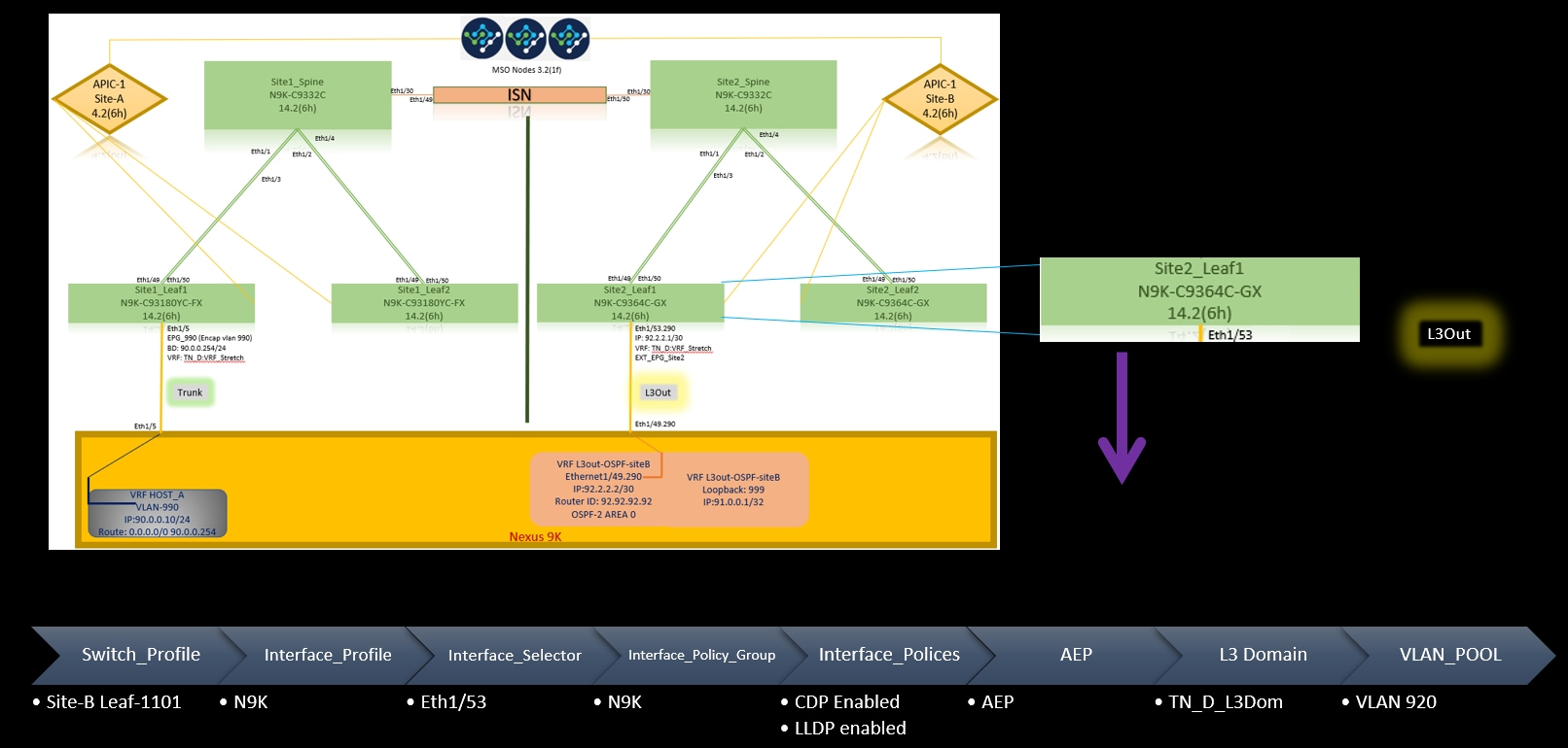
オプションの手順
それぞれの接続に対してファブリックポリシーを設定したら、すべてのリーフ/スパインが検出され、それぞれのAPICクラスタから到達可能であることを確認できます。次に、両方のサイト(APICクラスタ)がMSOから到達可能であり、マルチサイト設定が動作可能であること(およびIPN接続)を検証できます。
RTEP/ETEPの設定
サイト間L3outに必要な設定は、ルーティング可能なトンネルエンドポイントプール(RTEP)または外部トンネルエンドポイントプール(ETEP)です。旧バージョンのMSOでは「ルーティング可能なTEPプール」と表示されますが、新バージョンのMSOでは「外部TEPプール」と表示されますが、どちらも同義です。これらのTEPプールは、VRF「Overlay-1」を介してボーダーゲートウェイプロトコル(BGP)イーサネットVPN(EVPN)に使用されます。
L3outからの外部ルートは、BGP EVPNを介して別のサイトにアドバタイズされます。このRTEP/ETEPはリモートリーフの設定にも使用されるため、APICにすでに存在するETEP/RTEP設定がある場合は、MSOにインポートする必要があります。
MSO GUIからETEPを設定する手順を次に示します。バージョンは3.X MSOであるため、ETEPが表示されます。ETEPプールは各サイトで一意である必要があり、各サイトの内部EPG/BDサブネットと重複してはなりません。
サイトA
ステップ1:MSO GUIページ(Webページでマルチサイトコントローラを開く)で、[インフラストラクチャ] > [インフラストラクチャの設定]を選択します。[インフラスタの構成]をクリックします。

ステップ2:インターンInfraを設定し、Site-A、Inside Site-Aを選択し、pod-1を選択します。次にInside pod-1で、External TEP PoolsをSite-Aの外部TEP IPアドレスアドレスでを設定します(この192.168.200.0/24)。 サイトAにマルチPODがある場合は、他のポッドに対してこの手順を繰り返します。

ステップ3:APIC GUIでETEPプールの設定を確認するには、[Fabric] > [Inventory] > [Pod Fabric Setup Policy] > [Pod-ID] (ダブルクリックして[Fabric Setup Policy a POD-Pod-x]) > [External TEP]をを選択します。

次のコマンドを使用して、設定を確認することもできます。
moquery -c fabricExtRoutablePodSubnet
moquery -c fabricExtRoutablePodSubnet -f 'fabric.ExtRoutablePodSubnet.pool=="192.168.200.0/24"'
APIC1# moquery -c fabricExtRoutablePodSubnet
Total Objects shown: 1
# fabric.ExtRoutablePodSubnet
pool                 : 192.168.200.0/24
annotation           : orchestrator:msc
childAction          :
descr                :
dn                   : uni/controller/setuppol/setupp-1/extrtpodsubnet-[192.168.200.0/24]
extMngdBy            :
lcOwn                : local
modTs                : 2021-07-19T14:45:22.387+00:00
name                 :
nameAlias            :
reserveAddressCount  : 0
rn                   : extrtpodsubnet-[192.168.200.0/24]
state                : active
status               :
uid                  : 0
サイトB
ステップ1:Site-Bの外部TEPプールを設定します(Site-Aと同じ手順)。 MSO GUIページ(Webページでマルチサイトコントローラを開く)で、[インフラストラクチャ] > [インフラストラクチャの構成]を選択します。「インフラーラの構成」をクリックします。「インフララの構成」で「Site-B」を選択します。Inside Site-Bでpod-1を選択します。次に、Inside pod-1でExternal TEP Poolsに、Site-Bの外部TEP IPアドレスを設定します(この例では192.168.100.0/24)。 サイトBにマルチPODがある場合は、他のポッドに対してこの手順を繰り返します。

ステップ2:APIC GUIでETEPプールの設定を確認するには、[Fabric] > [Inventory] > [Pod Fabric Setup Policy] > [Pod-ID] (ダブルクリックして[Fabric Setup Policy a POD-Pod-x]) > [External TEP]をを選択します。
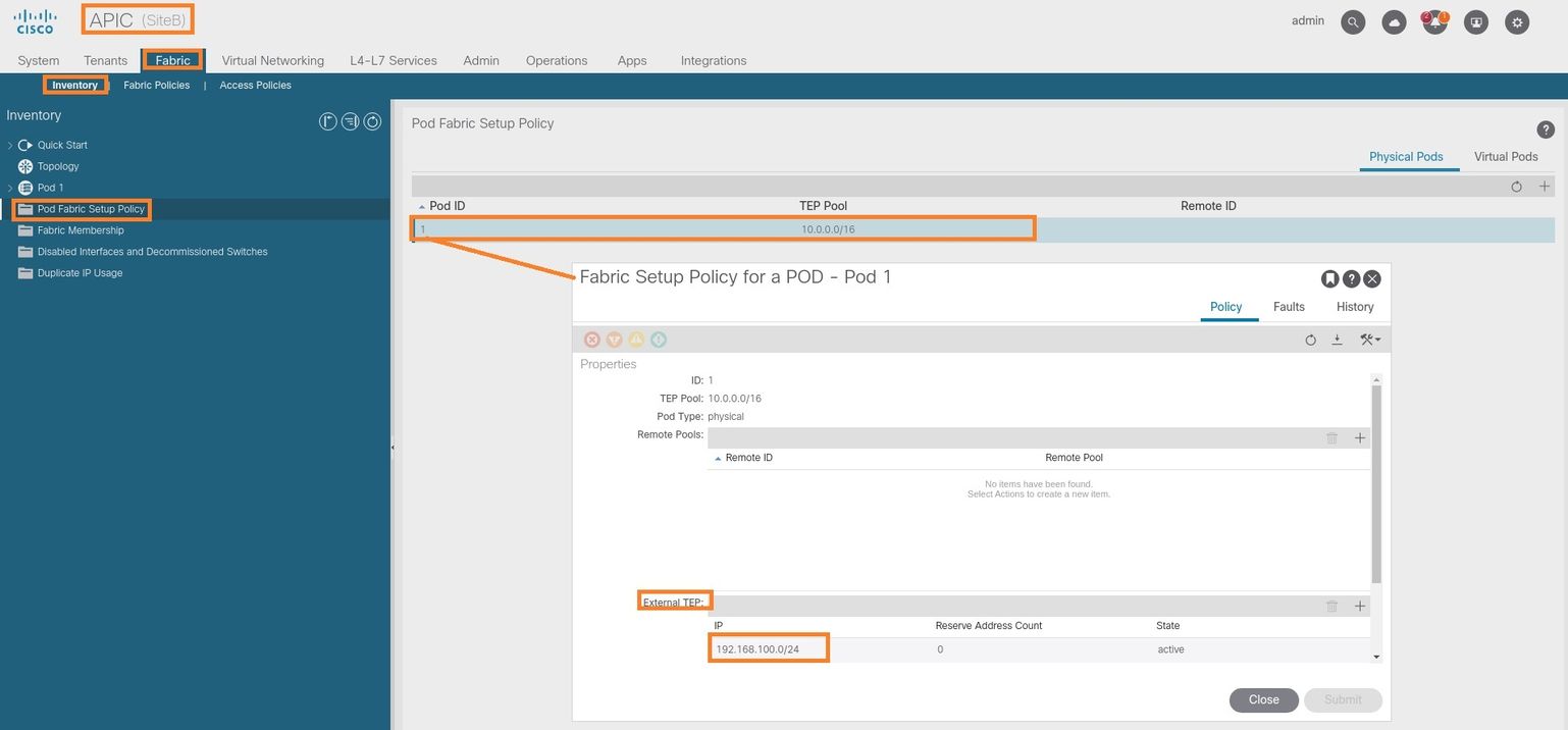
Site-B APICの場合は、次のコマンドを入力して、ETEPアドレスプールを確認します。
apic1# moquery -c fabricExtRoutablePodSubnet -f 'fabric.ExtRoutablePodSubnet.pool=="192.168.100.0/24"'
Total Objects shown: 1
# fabric.ExtRoutablePodSubnet
pool                 : 192.168.100.0/24
annotation           : orchestrator:msc  <<< This means, configuration pushed from MSO.
childAction          :
descr                :
dn                   : uni/controller/setuppol/setupp-1/extrtpodsubnet-[192.168.100.0/24]
extMngdBy            :
lcOwn                : local
modTs                : 2021-07-19T14:34:18.838+00:00
name                 :
nameAlias            :
reserveAddressCount  : 0
rn                   : extrtpodsubnet-[192.168.100.0/24]
state                : active
status               :
uid                  : 0
ストレッチテナントの設定
ステップ1:MSO GUIで、[Application Management] > [Tenants]を選択します。 [テナントの追加]をクリックします。この例では、テナント名は「TN_D」です。

ステップ2:[Display Name]フィールドに、テナントの名前を入力します。[関連するサイト]セクションで、[サイトA]および[サイトB]チェックボックスをオンにします。
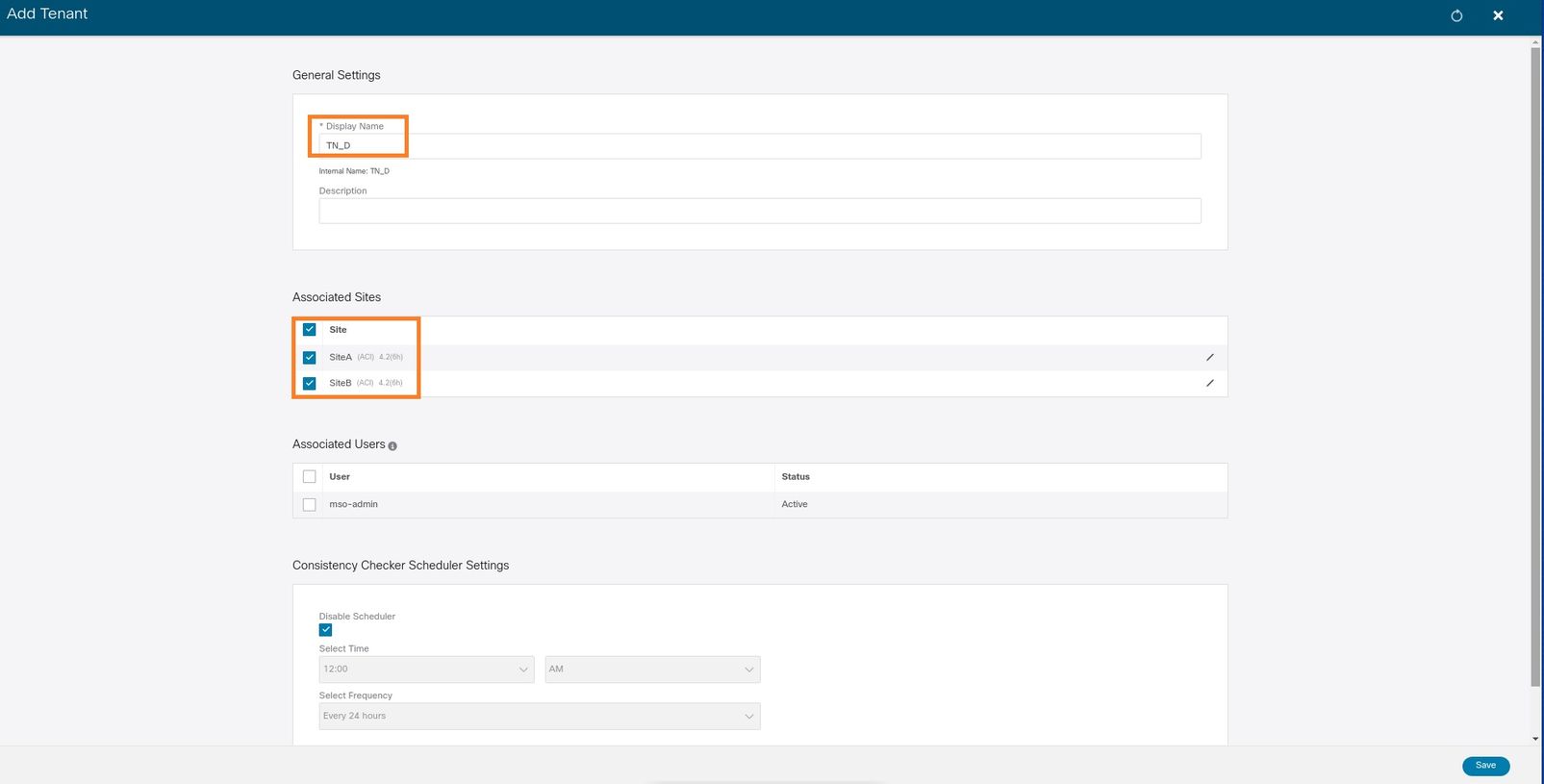
ステップ3:新しいテナント「Tn_D」が作成されていることを確認します。

論理構成図
MSOからテナントを作成すると、基本的にSite-AとSite-Bにテナントが作成されます。張子だ。この例では、このテナントの論理ビューを示します。この論理ビューは、テナントTN_DがSite-AとSite-Bの間で拡張されていることを理解するのに役立ちます。
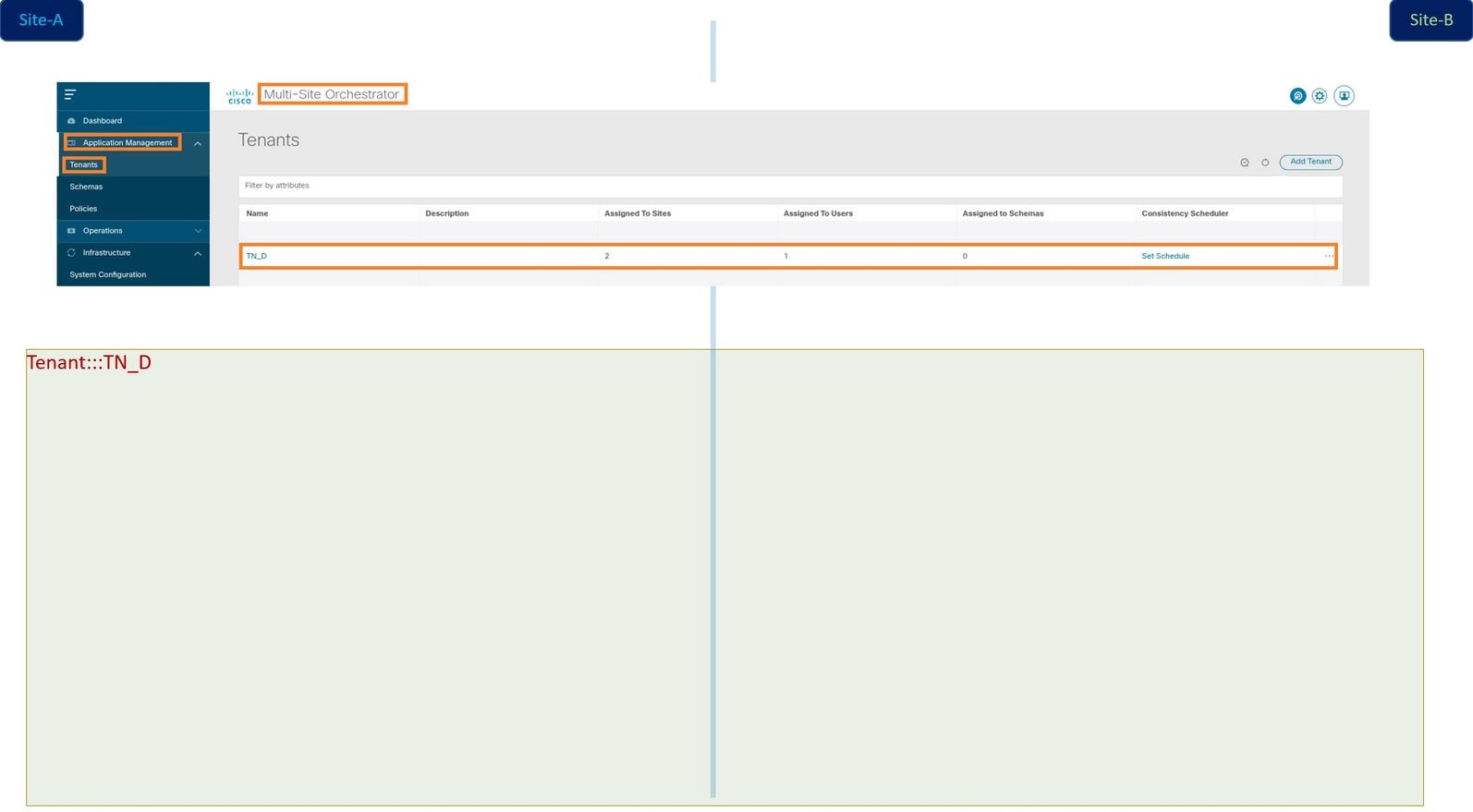
各サイトのAPICで論理ビューを確認できます。Site-AとSite-Bの両方で「TN_D」テナントが作成されたことを確認できます。

同じ拡張テナント「TN_D」もSite-Bで作成されます。

このコマンドは、MSOからプッシュされたテナントを表示し、検証のために使用できます。このコマンドは、両方のサイトのAPICで実行できます。
APIC1# moquery -c fvTenant -f 'fv.Tenant.name=="TN_D"'
Total Objects shown: 1
# fv.Tenant
name         : TN_D
annotation   : orchestrator:msc
childAction  :
descr        :
dn           : uni/tn-TN_D
extMngdBy    : msc
lcOwn        : local
modTs        : 2021-09-17T21:42:52.218+00:00
monPolDn     : uni/tn-common/monepg-default
nameAlias    :
ownerKey     :
ownerTag     :
rn           : tn-TN_D
status       :
uid          : 0
apic1# moquery -c fvTenant -f 'fv.Tenant.name=="TN_D"'
Total Objects shown: 1
# fv.Tenant
name         : TN_D
annotation   : orchestrator:msc
childAction  :
descr        :
dn           : uni/tn-TN_D
extMngdBy    : msc
lcOwn        : local
modTs        : 2021-09-17T21:43:04.195+00:00
monPolDn     : uni/tn-common/monepg-default
nameAlias    :
ownerKey     :
ownerTag     :
rn           : tn-TN_D
status       :
uid          : 0
スキーマの設定
次に、合計3つのテンプレートを持つスキーマを作成します。
- サイトAのテンプレート:Site-AのテンプレートはSite-Aにのみ関連付けられているため、そのテンプレート内の論理オブジェクト設定はSite-AのAPICにのみプッシュできます。
- Site-Bのテンプレート:Site-BのテンプレートはSite-Bにのみ関連付けられているため、そのテンプレート内の論理オブジェクト設定はSite-BのAPICにのみプッシュできます。
- 引き伸ばしテンプレート:拡張テンプレートは両方のサイトに関連付けられ、拡張テンプレート内の任意の論理設定はAPICの両方のサイトにプッシュできます。
スキーマの作成
スキーマはMSOではローカルで重要であり、APICではオブジェクトを作成しません。スキーマ設定は、各設定の論理的な分離です。同じテナントに対して複数のスキーマを持つことができ、各スキーマ内に複数のテンプレートを持つこともできます。
たとえば、テナントXのデータベースサーバのスキーマを持ち、アプリケーションサーバが同じテナントXに異なるスキーマを使用するとします。これは、特定のアプリケーション関連の各設定を分離するのに役立ち、問題をデバッグする必要がある場合は簡単です。情報を見つけるのも簡単です。
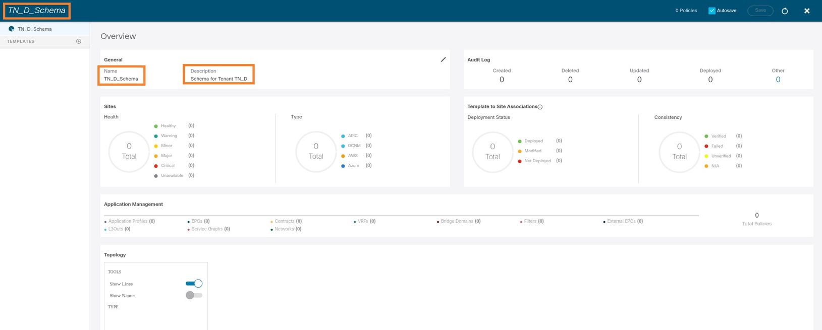
テナントの名前(TN_D_Schemaなど)を使用してスキーマを作成します。 ただし、テナント名でスキーマ名を始める必要はありません。任意の名前でスキーマを作成できます。
ステップ1:「アプリケーション管理」>「スキーマ」を選択します。「スキーマの追加」をクリックします。

ステップ2:[名前]フィールドに、スキーマの名前を入力します。この例では「TN_D_Schema」ですが、ご使用の環境に適した任意の名前を使用できます。[Add] をクリックします。

ステップ3:スキーマ「TN_D_Schema」が作成されたことを確認します。
サイトAテンプレートの作成
ステップ1:スキーマ内にテンプレートを追加します。
- テンプレートを作成するには、作成したスキーマの下の[Templates]をクリックします。[テンプレートの種類を選択]ダイアログボックスが表示されます。
- [ACI Multi-cloud]を選択します。
- [Add] をクリックします。

ステップ2:テンプレートの名前を入力します。このテンプレートはSite-Aに固有であるため、テンプレート名は「Site-A Template」です。 テンプレートを作成したら、特定のテナントをテンプレートにアタッチできます。この例では、テナント「TN_D」が接続されています。

テンプレートの設定
アプリケーションプロファイルの設定
ステップ1:作成したスキーマから、[Site-A Template]を選択します。「アプリケーション・プロファイルの追加」をクリックします。

ステップ2:[Display Name]フィールドに、アプリケーションプロファイル名App_Profileを入力します。
ステップ3:次のステップは、EPGを作成することです。アプリケーションプロファイルの下にEPGを追加するには、[Site-A]テンプレートの下の[Add EPG]をクリックします。新しいEPGがEPG設定内に作成されていることがわかります。

ステップ4:BDとVRFを使用してEPGを接続するには、EPGの下にBDとVRFを追加する必要があります。Site-A Templateを選択します。[表示名]フィールドに、EPGの名前を入力し、新しいBDをアタッチします(新しいBDを作成するか、既存のBDをアタッチできます)。

VRFをBDに接続する必要がありますが、この場合はVRFが拡張されます。拡張されたVRFを使用して拡張されたテンプレートを作成し、サイト固有のテンプレート(この場合はSite-A Template)の下でそのVRFをBDにアタッチします。
ストレッチテンプレートの作成
ステップ1:ストレッチテンプレートを作成するには、TN_D_Schemaの下の[Templates]をクリックします。[テンプレートの種類を選択]ダイアログボックスが表示されます。[ACI Multi-cloud]を選択します。[Add] をクリックします。テンプレートの名前Stretch Templateを入力します。(ストレッチされたテンプレートには、任意の名前を入力できます)。

ステップ2:[Stretch Template]を選択し、VRF_Stretchという名前のVRFを作成します。(VRFには任意の名前を入力できます)。

BDはSite-A TemplateでEPGを作成して作成されましたが、VRFがアタッチされていなかったため、拡張テンプレートで作成されたVRFをアタッチする必要があります。
ステップ3:[Site-A Template] > [BD_990]の順に選択します。[Virtual Routing & Forwarding]ドロップダウンリストで、[VRF_Stretch]を選択します。(このセクションのステップ2で作成したファイル)。

テンプレートの添付
次の手順では、サイトAテンプレートをサイトAのみと共に添付し、拡張されたテンプレートを両方のサイトに添付する必要があります。各サイトにテンプレートを展開するには、スキーマ内の[Deploy to site]をクリックします。
ステップ1:[TN_D_Schema] > [SITES]の下の+記号をクリックして、テンプレートにサイトを追加します。[テンプレートに割り当て]ドロップダウンリストで、該当するサイトの各テンプレートを選択します。
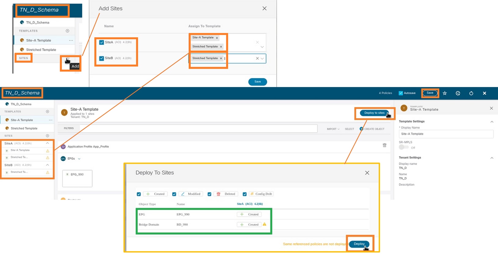
ステップ2:Site-AにEPGとBDが作成されていますが、Site-Bに同じEPG/BDが作成されていないことがわかります。これは、これらの設定がMSOのSite-Aにのみ適用されるためです。ただし、VRFがストレッチテンプレートに作成され、両方のサイトに作成されていることがわかります。

ステップ3:次のコマンドを使用して設定を確認します。
APIC1# moquery -c fvAEPg -f 'fv.AEPg.name=="EPG_990"'
Total Objects shown: 1
# fv.AEPg
name                 : EPG_990
annotation           : orchestrator:msc
childAction          :
configIssues         :
configSt             : applied
descr                :
dn                   : uni/tn-TN_D/ap-App_Profile/epg-EPG_990
exceptionTag         :
extMngdBy            :
floodOnEncap         : disabled
fwdCtrl              :
hasMcastSource       : no
isAttrBasedEPg       : no
isSharedSrvMsiteEPg  : no
lcOwn                : local
matchT               : AtleastOne
modTs                : 2021-09-18T08:26:49.906+00:00
monPolDn             : uni/tn-common/monepg-default
nameAlias            :
pcEnfPref            : unenforced
pcTag                : 32770
prefGrMemb           : exclude
prio                 : unspecified
rn                   : epg-EPG_990
scope                : 2850817
shutdown             : no
status               :
triggerSt            : triggerable
txId                 : 1152921504609182523
uid                  : 0
APIC1# moquery -c fvBD -f 'fv.BD.name=="BD_990"'
Total Objects shown: 1
# fv.BD
name                     : BD_990
OptimizeWanBandwidth     : yes
annotation               : orchestrator:msc
arpFlood                 : yes
bcastP                   : 225.0.56.224
childAction              :
configIssues             :
descr                    :
dn                       : uni/tn-TN_D/BD-BD_990
epClear                  : no
epMoveDetectMode         :
extMngdBy                :
hostBasedRouting         : no
intersiteBumTrafficAllow : yes
intersiteL2Stretch       : yes
ipLearning               : yes
ipv6McastAllow           : no
lcOwn                    : local
limitIpLearnToSubnets    : yes
llAddr                   : ::
mac                      : 00:22:BD:F8:19:FF
mcastAllow               : no
modTs                    : 2021-09-18T08:26:49.906+00:00
monPolDn                 : uni/tn-common/monepg-default
mtu                      : inherit
multiDstPktAct           : bd-flood
nameAlias                :
ownerKey                 :
ownerTag                 :
pcTag                    : 16387
rn                       : BD-BD_990
scope                    : 2850817
seg                      : 16580488
status                   :
type                     : regular
uid                      : 0
unicastRoute             : yes
unkMacUcastAct           : proxy
unkMcastAct              : flood
v6unkMcastAct            : flood
vmac                     : not-applicable
               : 0
APIC1# moquery -c fvCtx -f 'fv.Ctx.name=="VRF_Stretch"'
Total Objects shown: 1
# fv.Ctx
name                 : VRF_Stretch
annotation           : orchestrator:msc
bdEnforcedEnable     : no
childAction          :
descr                :
dn                   : uni/tn-TN_D/ctx-VRF_Stretch
extMngdBy            :
ipDataPlaneLearning  : enabled
knwMcastAct          : permit
lcOwn                : local
modTs                : 2021-09-18T08:26:58.185+00:00
monPolDn             : uni/tn-common/monepg-default
nameAlias            :
ownerKey             :
ownerTag             :
pcEnfDir             : ingress
pcEnfDirUpdated      : yes
pcEnfPref            : enforced
pcTag                : 16386
rn                   : ctx-VRF_Stretch
scope                : 2850817
seg                  : 2850817
status               :
uid                  : 0
スタティックポートバインドの設定
これで、EPG「EPG_990」でスタティックポートバインドを設定し、VRF HOST_A(基本的にはHOST_Aをシミュレート)でN9Kを設定できます。 ACI側のスタティックポートバインド設定が最初に完了します。
ステップ1:EPG_990の下に物理ドメインを追加します。
- 作成したスキーマから、Site-A Template > EPG_990の順に選択します。
- [テンプレートのプロパティ]ボックスの[ドメインの追加]をクリックします。
- [ドメインの追加]ダイアログボックスで、ドロップダウンリストから次のオプションを選択します。
- ドメインの関連付けタイプ – 物理
- ドメインプロファイル – TN_D_PhysDom
- 導入の即時性 – 即時
- 解決の即時性 – 即時
- [Save] をクリックします。

ステップ2:スタティックポート(Site1_Leaf1 eth1/5)を追加します。
- 作成したスキーマから、[Site-A Template] > [EPG_990]を選択します。
- [テンプレートのプロパティ]ボックスの[静的ポートの追加]をクリックします。
- [Add Static EPG on PC, VPC or Interface]ダイアログボックスで、[Node-101 eth1/5]を選択し、VLAN 990を割り当てます。

ステップ3:静的ポートと物理ドメインがEPG_990に追加されていることを確認します。
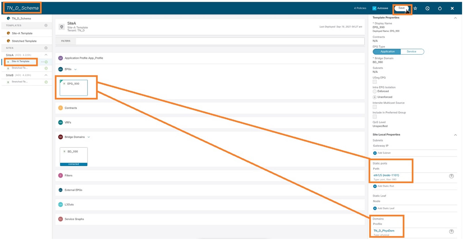
次のコマンドを使用して、スタティックパスバインドを確認します。
APIC1# moquery -c fvStPathAtt -f 'fv.StPathAtt.pathName=="eth1/5"' | grep EPG_990 -A 10 -B 5
# fv.StPathAtt
pathName     : eth1/5
childAction  :
descr        :
dn           : uni/epp/fv-[uni/tn-TN_D/ap-App_Profile/epg-EPG_990]/node-1101/stpathatt-[eth1/5]
lcOwn        : local
modTs        : 2021-09-19T06:16:46.226+00:00
monPolDn     : uni/tn-common/monepg-default
name         :
nameAlias    :
ownerKey     :
ownerTag     :
rn           : stpathatt-[eth1/5]
status       :
BDの設定
ステップ1:BDの下にサブネット/IPを追加します(HOST_AはゲートウェイとしてBD IPを使用します)。
- 作成したスキーマから、[Site-A Template] > [BD_990]を選択します。
- [サブネットの追加]をクリックします。
- [新しいサブネットの追加]ダイアログボックスで、ゲートウェイのIPアドレスを入力し、[外部からアドバタイズ]ラジオボタンをクリックします。
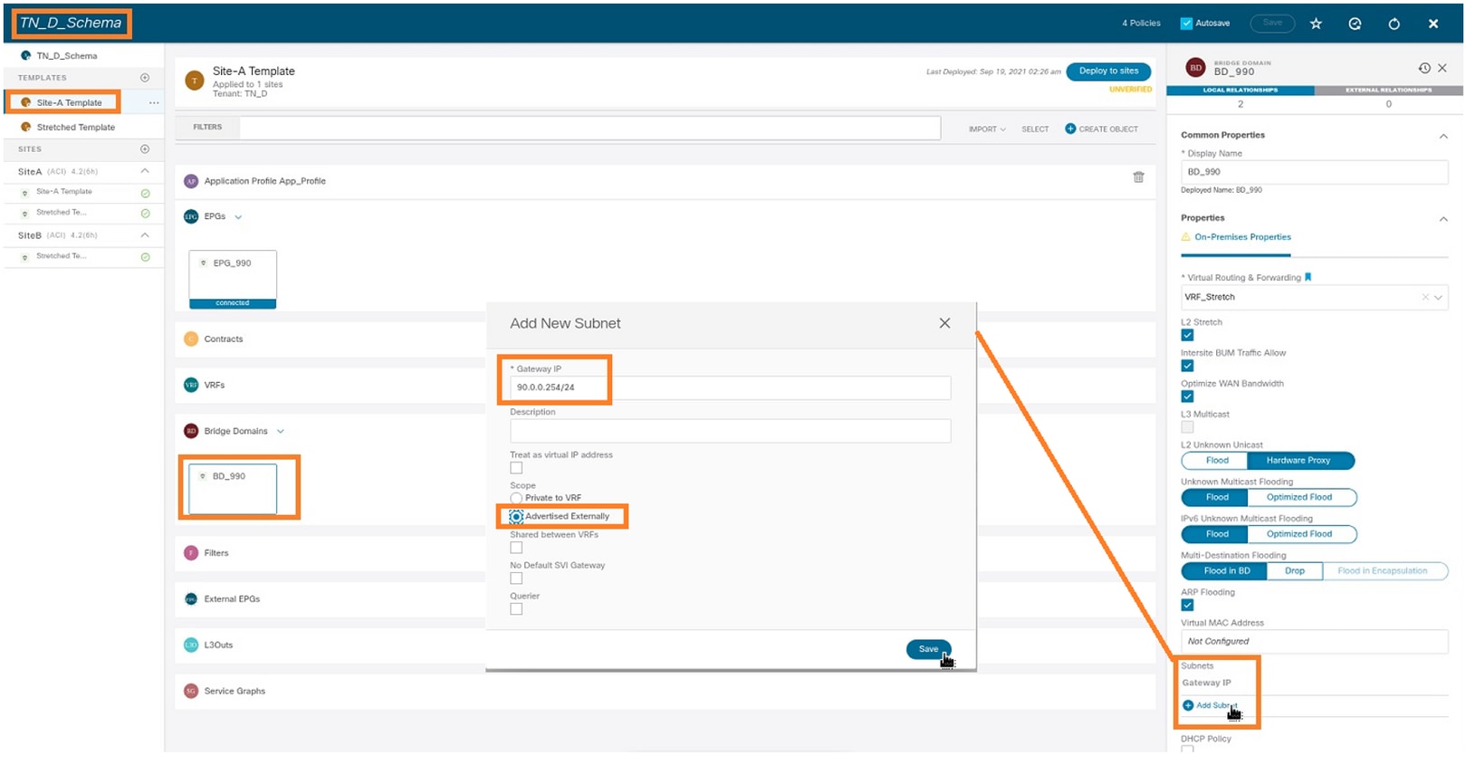
手順2:このコマンドを使用して、サブネットがAPIC1 Site-Aに追加されていることを確認します。
APIC1# moquery -c fvSubnet -f 'fv.Subnet.ip=="90.0.0.254/24"'
Total Objects shown: 1

# fv.Subnet
ip           : 90.0.0.254/24
annotation   : orchestrator:msc
childAction  :
ctrl         : nd
descr        :
dn           : uni/tn-TN_D/BD-BD_990/subnet-[90.0.0.254/24]
extMngdBy    :
lcOwn        : local
modTs        : 2021-09-19T06:33:19.943+00:00
monPolDn     : uni/tn-common/monepg-default
name         :
nameAlias    :
preferred    : no
rn           : subnet-[90.0.0.254/24]
scope        : public
status       :
uid          : 0
virtual      : no
ステップ3:サイトAテンプレートを導入します。
- 作成したスキーマから、[Site-A Template]を選択します。
- [サイトに配置]をクリックします。
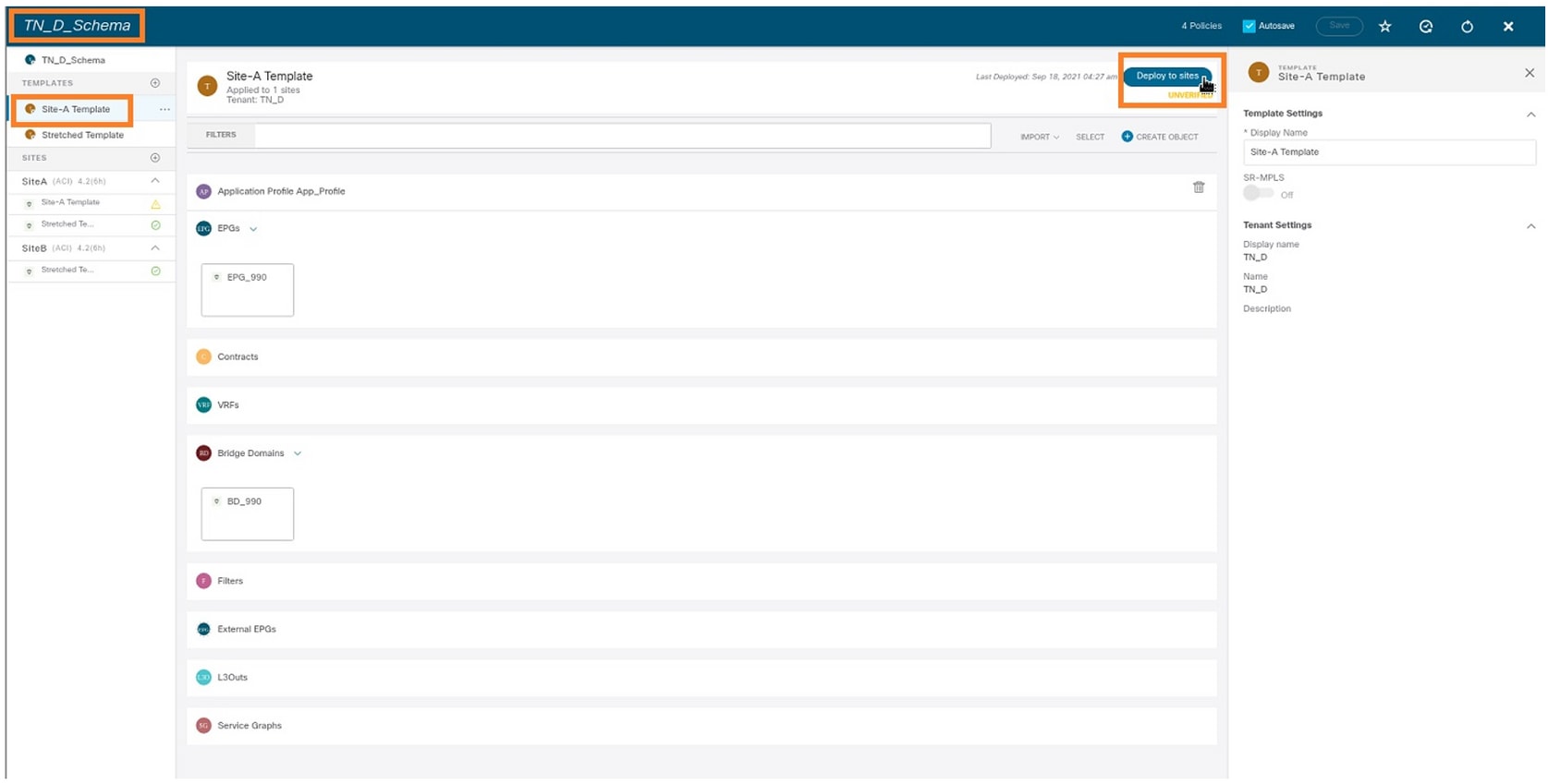
ホストA(N9K)の設定
VRF HOST_Aを使用してN9Kデバイスを設定します。N9Kの設定が完了すると、ACIリーフBDエニーキャストアドレス(HOST_Aのゲートウェイ)がICMP(ping)経由で到達可能になったことがわかります。

ACIの[operational]タブには、90.0.0.10(HOST_A IPアドレス)が学習されたことが表示されます。
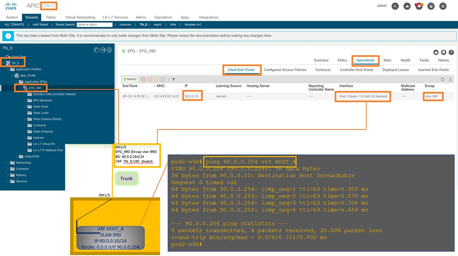
Site-Bテンプレートの作成
ステップ1:作成したスキーマから、[TEMPLATES]を選択します。+記号をクリックし、Site-B Templateという名前のテンプレートを作成します。

Site-B L3outの設定
L3outを作成し、VRF_Stretchを接続します。MSOからL3outオブジェクトを作成し、残りのL3out設定はAPICから行う必要があります(L3outパラメータはMSOでは使用できません)。 また、MSOから外部EPGを作成します(外部EPGは延長されないため、サイトBテンプレートでのみ)。
ステップ1:作成したスキーマから、[Site-B Template]を選択します。[表示名]フィールドにL3out_OSPF_siteBと入力します。[仮想ルーティングと転送]ドロップダウンリストで、[VRF_Stretch]を選択します。
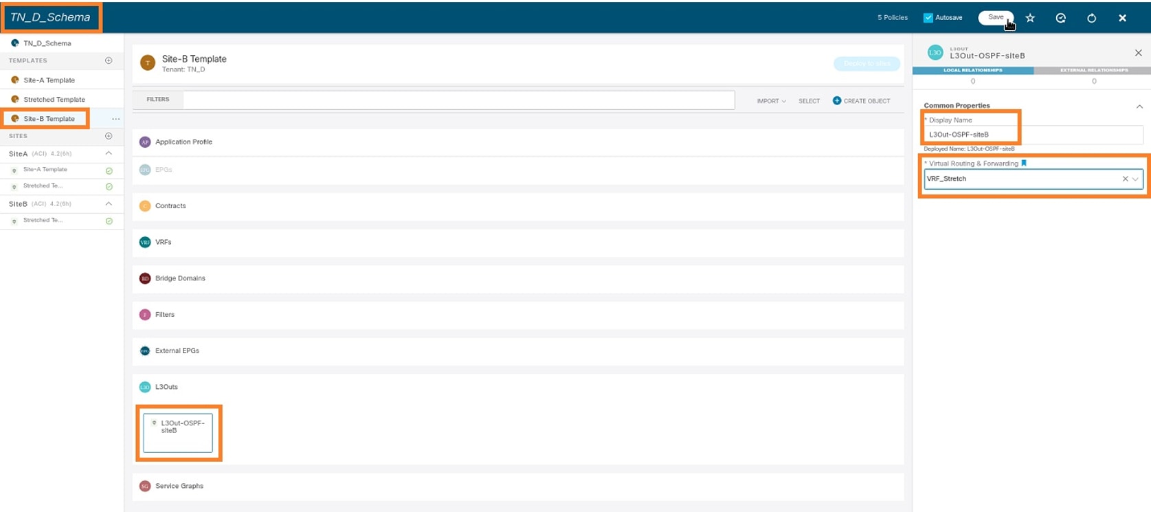
外部EPGの作成
ステップ1:作成したスキーマから、[Site-B Template]を選択します。[Add External EPG]をクリックします。

ステップ2:外部EPGでL3outを接続します。
- 作成したスキーマから、[Site-B Template]を選択します。
- [表示名]フィールドにEXT_EPG_Site2と入力します。
- [Classification Subnets]フィールドに、外部EPGの外部サブネットに0.0.0.0/0と入力します。

残りのL3out設定は、APIC(Site-B)から行います。
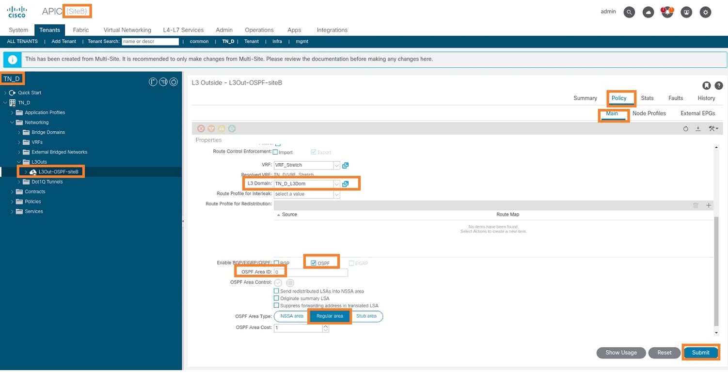
手順3:L3ドメインを追加し、OSPFプロトコルを有効にし、通常のエリア0でOSPFを設定します。
- APIC-1のSite-Bで、[TN_D] > [Networking] > [L3out-OSPF-siteB] > [Policy] > [Main]を選択します。
- [L3 Domain]ドロップダウンリストで、[TN_D_L3Dom]を選択します。
- [Enable BGP/EIGRP/OSPF]の[OSPF]]チェックボックスをオンにします。
- [OSPF Area ID]フィールドに、0と入力します。
- [OSPF Area Type]で、[Regular area]を選択します。
- [Submit] をクリックします。
ステップ4:ノードプロファイルを作成します。
- APIC-1のSite-Bで、[TN_D] > [Networking] > [L3Outs] > [L3Out-OSPF-siteB] > [Logical Node Profiles]を選択します。
- [ノードプロファイルを作成]をクリックします。

ステップ5:site-Bのノードとしてswitch Site2_Leaf1を選択します。
- Site-BのAPIC-1から、[TN_D] > [Networking] > [L3Outs] > [L3Out-OSPF-siteB] > [Logical Node Profiles] > [Create Node Profile] を選択します。
- [名前]フィールドに、Site2_Leaf1と入力します。
- +記号をクリックして、ノードを追加します。
- ルータIDのIPアドレスを使用してpod-2 node-101を追加します。

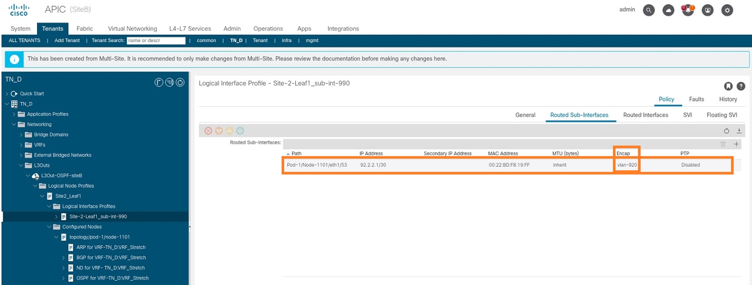
ステップ6:インターフェイスプロファイルを追加します(外部VLANは920(SVIの作成))。
- Site-BのAPIC-1から、[TN_D] > [Networking] > [L3Outs] > [L3out-OSPF-SiteB] > [Logical Interface Profiles] を選択します。
- 右クリックして、インターフェイスプロファイルを追加します。
- [ルーテッドサブインターフェイス]を選択します。
- IPアドレス、MTU、およびVLAN-920を設定します。
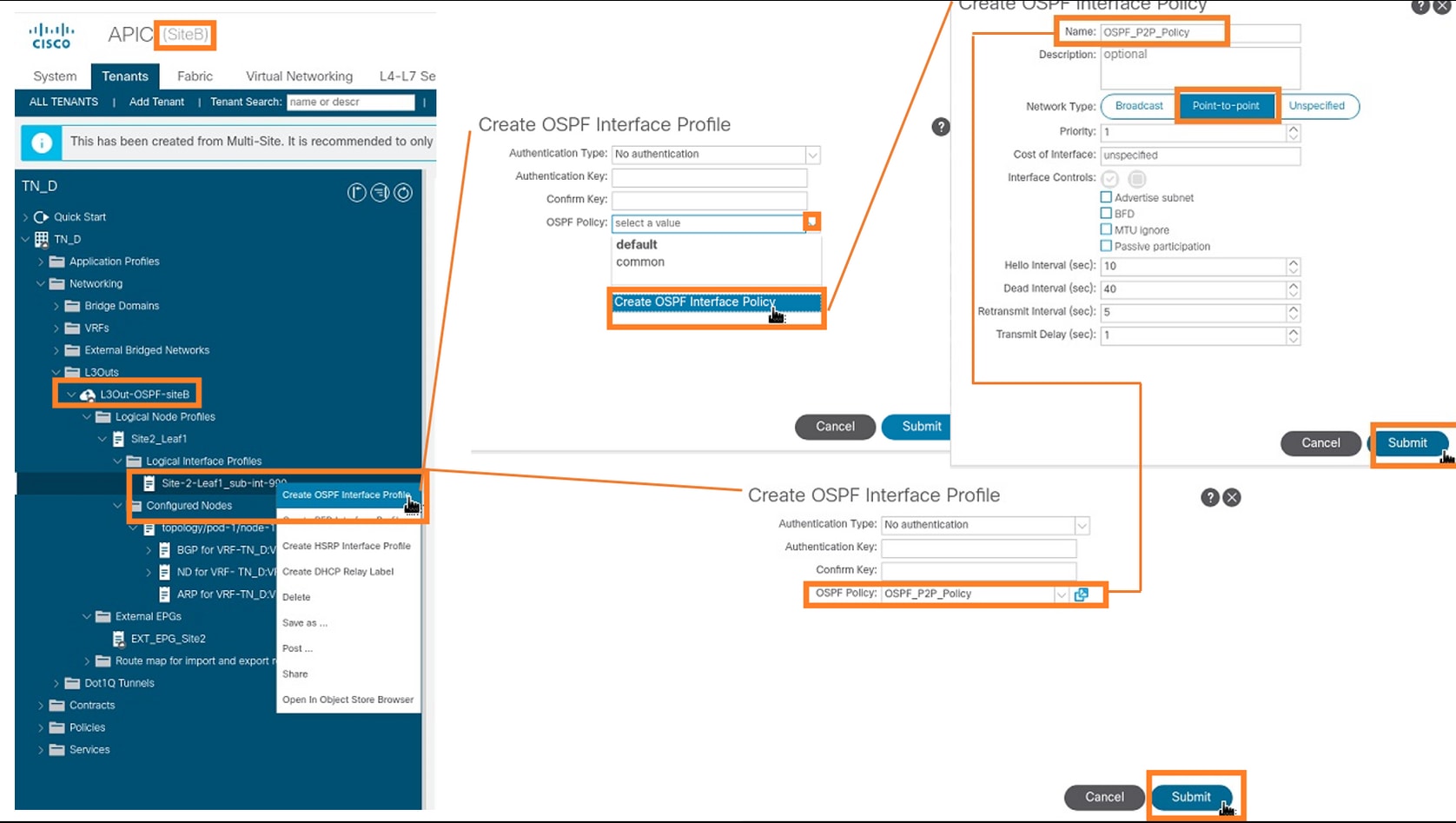
ステップ7:OSPFポリシー(ポイントツーポイントネットワーク)を作成します。
- APIC-1のSite-Bで、[TN_D] > [Networking] > [L3Outs] > [L3Out-OSPF-siteB] > [Logical Interface Profiles]を選択します。
- 右クリックして、[Create OSPF Interface Profile]を選択します。
- スクリーンショットに示されているオプションを選択し、[送信]をクリックします。
ステップ8:[TN_D] > [Networking] > [L3Outs] > [L3Out-OSPF-siteB] > [Logical Interface Profiles] > (interface profile) > [OSPF Interface Profile]の下に添付されているOSPFインターフェイスプロファイルポリシーを確認します。

ステップ9:外部EPG「EXT_EPG_Site2」がMSOによって作成されていることを確認します。APIC-1のSite-Bで、[TN_D] > [L3Outs] > [L3Out-OSPF-siteB] > [External EPGs] > [EXT_EPG_Site2]を選択します。

外部N9K(サイトB)の設定
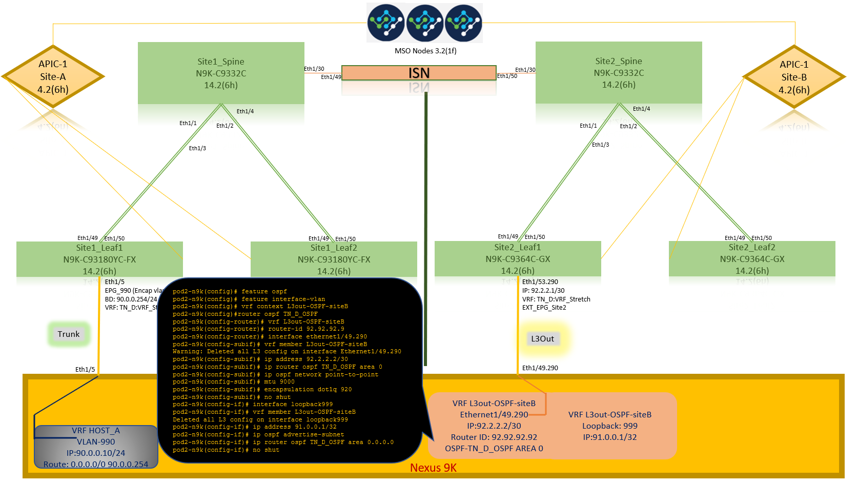
N9K設定(VRF L3out-OSPF-siteB)の後、N9KとACIリーフ(サイトB)の間でOSPFネイバーシップが確立されていることがわかります。
OSPFネイバーシップが確立され、UP(Full State)であることを確認します。
APIC-1から、Site-Bで[TN_D] > [Networking] > [L3Outs] > [L3Out-OSPF-siteB] > [Logical Node Profiles] > [Configured Nodes] > [topology/pod01/node-1101] > [OSPF for VRF-VRF-TN DVRF_Switch > Neighbor ID state > Full。
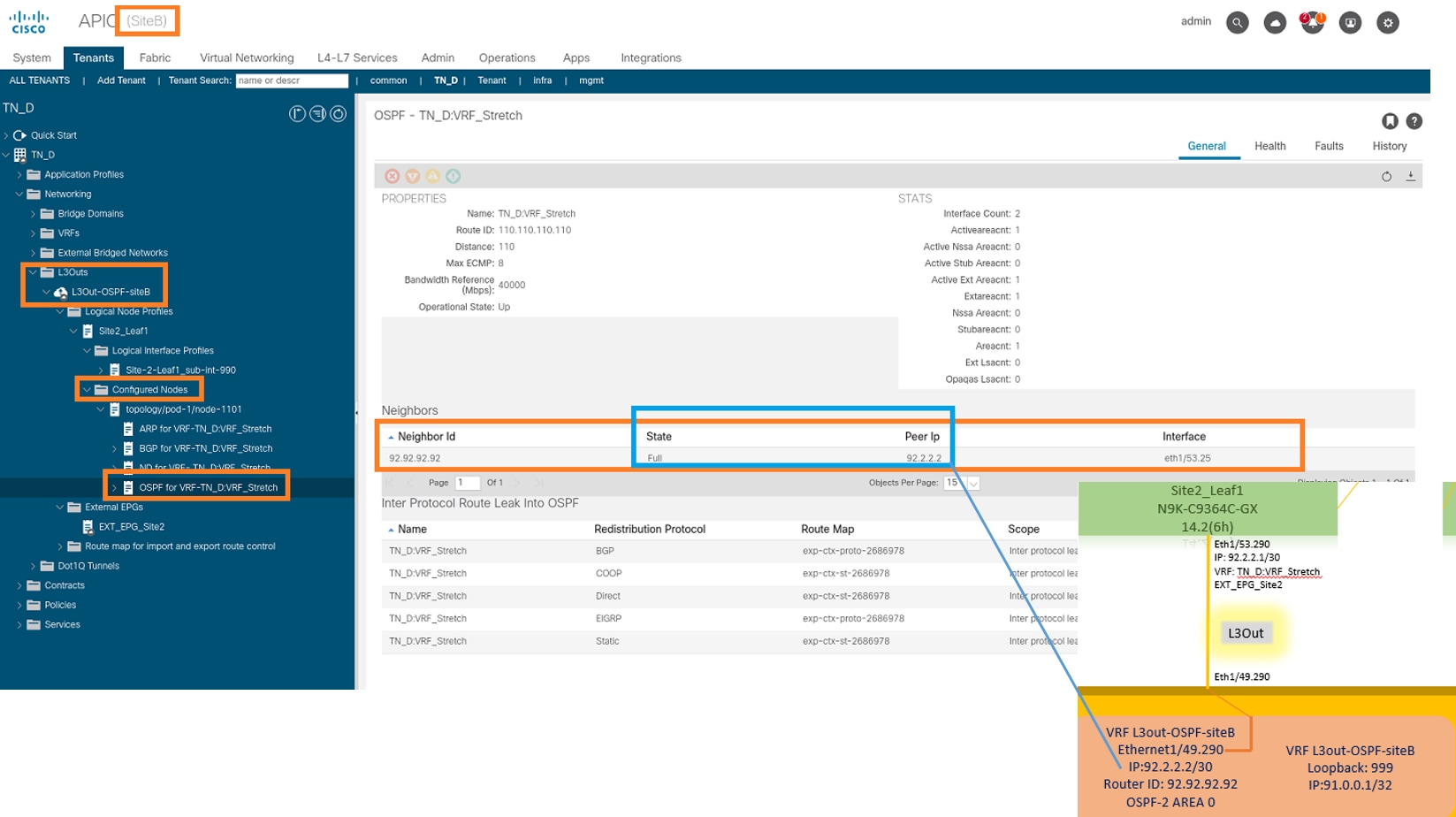
N9KでOSPFネイバーシップを確認することもできます。また、ACIリーフIP(サイトB)にpingを実行できます。

この時点で、site-AでのHost_A設定と、site-BでのL3out設定が完了します。

Site-B L3outをSite-A EPG(BD)に接続
次に、MSOからSite-B L3outをSite-A BD-990に接続します。左側の列には2つのセクションがあります。1)テンプレート、2)サイト。
ステップ1:2番目のセクションの[サイト]で、各サイトに添付されているテンプレートを確認できます。L3outを「Site-A Template」に接続すると、基本的にはサイトのセクション内に既に接続されているテンプレートから接続されます。
ただし、テンプレートを展開する場合は、[テンプレート] > [サイトAテンプレート]セクションから展開し、サイトに保存/展開を選択します。


ステップ2:最初のセクション「テンプレート」のメインテンプレート「Site-Aテンプレート」から導入します。

契約の設定
サイトBの外部EPGとサイトAの内部EPG_990の間の契約が必要です。そのため、まずMSOから契約を作成し、両方のEPGに関連付けることができます。
Cisco Application Centric Infrastructure - Cisco ACI契約ガイドは、契約の理解に役立ちます。通常、内部EPGはプロバイダーとして設定され、外部EPGはコンシューマとして設定されます。

契約の作成
ステップ1:TN_D_Schemaから、[Stretted Template] > [Contracts]を選択します。クリック 契約の追加

ステップ2:すべてのトラフィックを許可するフィルタを追加します。
- TN_D_Schemaから、[Stretted Template] > [Contracts]を選択します。
- 次の内容で契約を追加します。
- 表示名:Intersite-L3out-Contract
- Scope: VRF

ステップ 3:
- TN_D_Schemaから、[Stretted Template] > [Filters]を選択します。
- [Display Name]フィールドにAllow-all-trafficと入力します。
- [エントリの追加]をクリックします。[エントリの追加(Add Entry)]ダイアログボックスが表示されます。
- [名前]フィールドにAny_Trafficと入力します。
- [Ether Type]ドロップダウンリストで、[unspecified]を選択して、すべてのトラフィックを許可します。
- [Save] をクリックします。

ステップ4:外部EPGに「コンシューマ」(サイトBテンプレート)として契約を追加します(サイトに導入)。
- TN_D_Schemaから、Site-B Template > EXT_EPG_Site2の順に選択します。
- [契約の追加]をクリックします。[Add Contract]ダイアログボックスが表示されます。
- [契約]フィールドに、Intersite-L3out-Contractと入力します。
- [タイプ]ドロップダウンリストで、[コンシューマ]を選択します。
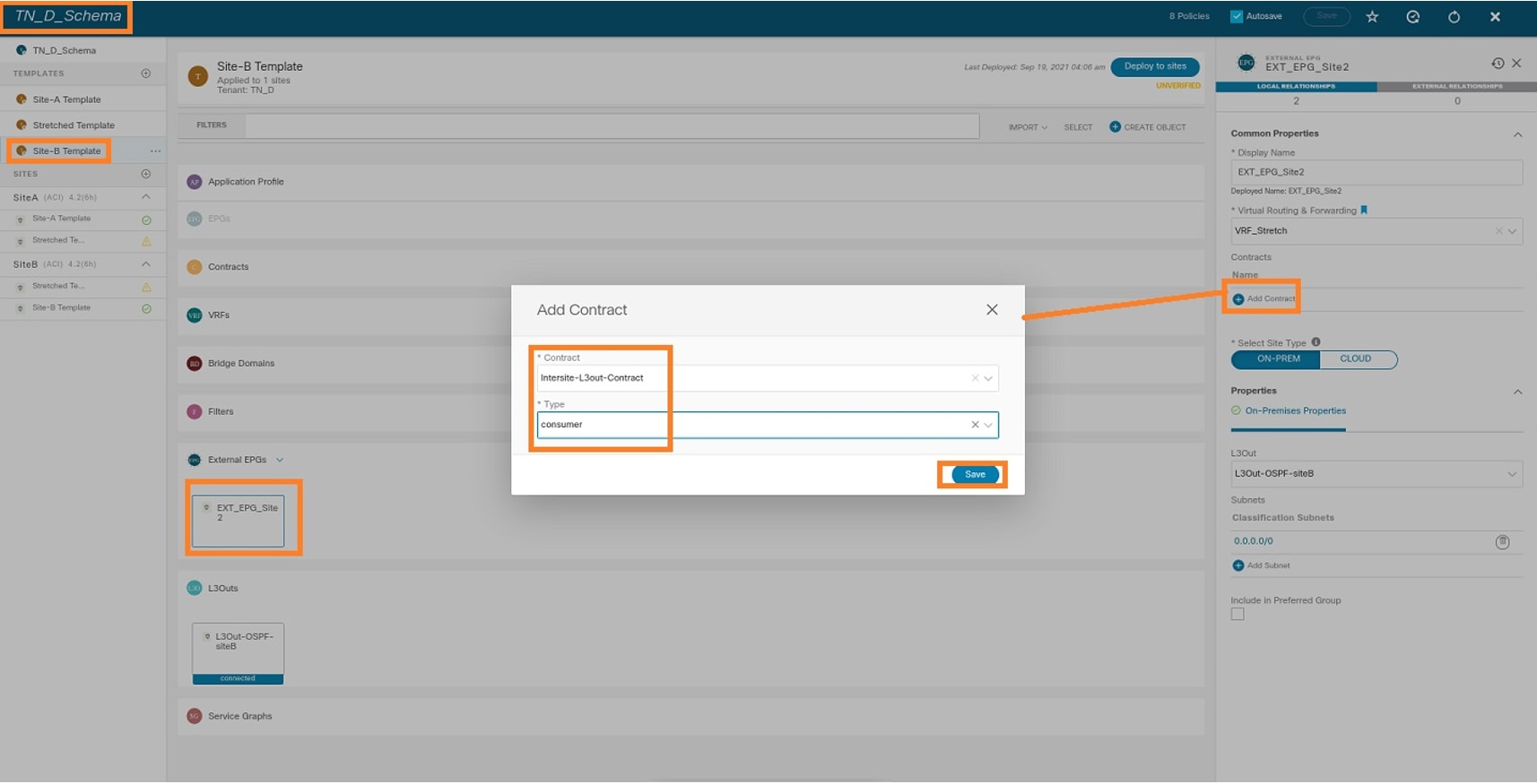
ステップ5:内部EPG「EPG_990」に「プロバイダー」(サイトAテンプレート内)として契約を追加します(サイトに展開)。
- TN_D_Schemaから、Site-A Template > EPG_990を選択します。
- [契約の追加]をクリックします。[Add Contract]ダイアログボックスが表示されます。
- [Contract]フィールドに、Intersite-L3out-Contractと入力します。
- [タイプ]ドロップダウンリストで、[プロバイダ]を選択します。

契約が追加されると、サイトAで「Shadow L3out / External EPG」が作成されます。

また、「Shadow EPG_990とBD_990」がSite-Bで作成されていることも確認できます。

ステップ6:次のコマンドを入力して、Site-B APICを確認します。
apic1# moquery -c fvAEPg -f 'fv.AEPg.name=="EPG_990"'
Total Objects shown: 1
# fv.AEPg
name                 : EPG_990
annotation           : orchestrator:msc
childAction          :
configIssues         :
configSt             : applied
descr                :
dn                   : uni/tn-TN_D/ap-App_Profile/epg-EPG_990
exceptionTag         :
extMngdBy            :
floodOnEncap         : disabled
fwdCtrl              :
hasMcastSource       : no
isAttrBasedEPg       : no
isSharedSrvMsiteEPg  : no
lcOwn                : local
matchT               : AtleastOne
modTs                : 2021-09-19T18:47:53.374+00:00
monPolDn             : uni/tn-common/monepg-default
nameAlias            :
pcEnfPref            : unenforced
pcTag                : 49153          <<< Note that pcTag is different for shadow EPG.
prefGrMemb           : exclude
prio                 : unspecified
rn                   : epg-EPG_990
scope                : 2686978
shutdown             : no
status               :
triggerSt            : triggerable
txId                 : 1152921504609244629
uid                  : 0
apic1# moquery -c fvBD -f 'fv.BD.name==\"BD_990\"'
Total Objects shown: 1
# fv.BD
name                     : BD_990
OptimizeWanBandwidth     : yes
annotation               : orchestrator:msc
arpFlood                 : yes
bcastP                   : 225.0.181.192
childAction              :
configIssues             :
descr                    :
dn                       : uni/tn-TN_D/BD-BD_990
epClear                  : no
epMoveDetectMode         :
extMngdBy                :
hostBasedRouting         : no
intersiteBumTrafficAllow : yes
intersiteL2Stretch       : yes
ipLearning               : yes
ipv6McastAllow           : no
lcOwn                    : local
limitIpLearnToSubnets    : yes
llAddr                   : ::
mac                      : 00:22:BD:F8:19:FF
mcastAllow               : no
modTs                    : 2021-09-19T18:47:53.374+00:00
monPolDn                 : uni/tn-common/monepg-default
mtu                      : inherit
multiDstPktAct           : bd-flood
nameAlias                :
ownerKey                 :
ownerTag                 :
pcTag                    : 32771
rn                       : BD-BD_990
scope                    : 2686978
seg                      : 15957972
status                   :
type                     : regular
uid                      : 0
unicastRoute             : yes
unkMacUcastAct           : proxy
unkMcastAct              : flood
v6unkMcastAct            : flood
vmac                     : not-applicable
ステップ7:外部デバイスのN9K設定を確認します。

確認
ここでは、設定が正常に機能しているかどうかを確認します。
エンドポイント学習
Site-AエンドポイントがSite1_Leaf1でエンドポイントとして学習されたことを確認します。
Site1_Leaf1# show endpoint interface ethernet 1/5
Legend:
 s - arp              H - vtep             V - vpc-attached     p - peer-aged
 R - peer-attached-rl B - bounce           S - static           M - span
 D - bounce-to-proxy  O - peer-attached    a - local-aged       m - svc-mgr
 L - local            E - shared-service
+-----------------------------------+---------------+-----------------+--------------+-------------+
      VLAN/                           Encap           MAC Address       MAC Info/       Interface
      Domain                          VLAN            IP Address        IP Info
+-----------------------------------+---------------+-----------------+--------------+-------------+
18                                         vlan-990    c014.fe5e.1407 L                      eth1/5
TN_D:VRF_Stretch                           vlan-990         90.0.0.10 L                      eth1/5
ETEP/RTEPの検証
Site_Aリーフ
Site1_Leaf1# show ip interface brief vrf overlay-1
IP Interface Status for VRF "overlay-1"(4)
Interface            Address              Interface Status
eth1/49              unassigned           protocol-up/link-up/admin-up
eth1/49.7            unnumbered           protocol-up/link-up/admin-up
                     (lo0)
eth1/50              unassigned           protocol-up/link-up/admin-up
eth1/50.8            unnumbered           protocol-up/link-up/admin-up
                     (lo0)
eth1/51              unassigned           protocol-down/link-down/admin-up
eth1/52              unassigned           protocol-down/link-down/admin-up
eth1/53              unassigned           protocol-down/link-down/admin-up
eth1/54              unassigned           protocol-down/link-down/admin-up
vlan9                10.0.0.30/27         protocol-up/link-up/admin-up
lo0                  10.0.80.64/32        protocol-up/link-up/admin-up
lo1                  10.0.8.67/32         protocol-up/link-up/admin-up
lo8                  192.168.200.225/32   protocol-up/link-up/admin-up  <<<<< IP from ETEP site-A
lo1023               10.0.0.32/32         protocol-up/link-up/admin-up
Site2_Leaf1# show ip interface brief vrf overlay-1
IP Interface Status for VRF "overlay-1"(4)
Interface            Address              Interface Status
eth1/49              unassigned           protocol-up/link-up/admin-up
eth1/49.16           unnumbered           protocol-up/link-up/admin-up
                     (lo0)
eth1/50              unassigned           protocol-up/link-up/admin-up
eth1/50.17           unnumbered           protocol-up/link-up/admin-up
                     (lo0)
eth1/51              unassigned           protocol-down/link-down/admin-up
eth1/52              unassigned           protocol-down/link-down/admin-up
eth1/54              unassigned           protocol-down/link-down/admin-up
eth1/55              unassigned           protocol-down/link-down/admin-up
eth1/56              unassigned           protocol-down/link-down/admin-up
eth1/57              unassigned           protocol-down/link-down/admin-up
eth1/58              unassigned           protocol-down/link-down/admin-up
eth1/59              unassigned           protocol-down/link-down/admin-up
eth1/60              unassigned           protocol-down/link-down/admin-up
eth1/61              unassigned           protocol-down/link-down/admin-up
eth1/62              unassigned           protocol-down/link-down/admin-up
eth1/63              unassigned           protocol-down/link-down/admin-up
eth1/64              unassigned           protocol-down/link-down/admin-up
vlan18               10.0.0.30/27         protocol-up/link-up/admin-up
lo0                  10.0.72.64/32        protocol-up/link-up/admin-up
lo1                  10.0.80.67/32        protocol-up/link-up/admin-up
lo6                  192.168.100.225/32   protocol-up/link-up/admin-up <<<<< IP from ETEP site-B
lo1023               10.0.0.32/32         protocol-up/link-up/admin-up
ICMP到達可能性
HOST_Aから外部デバイスのWAN IPアドレスにpingを実行します。

外部デバイスのループバックアドレスをpingします。

ルート検証
外部デバイスのWAN IPアドレスまたはループバックサブネットルートがルーティングテーブルに存在することを確認します。「Site1_Leaf1」で外部デバイスサブネットのネクストホップを確認すると、リーフ「Site2-Leaf1」の外部TEP IPになります。
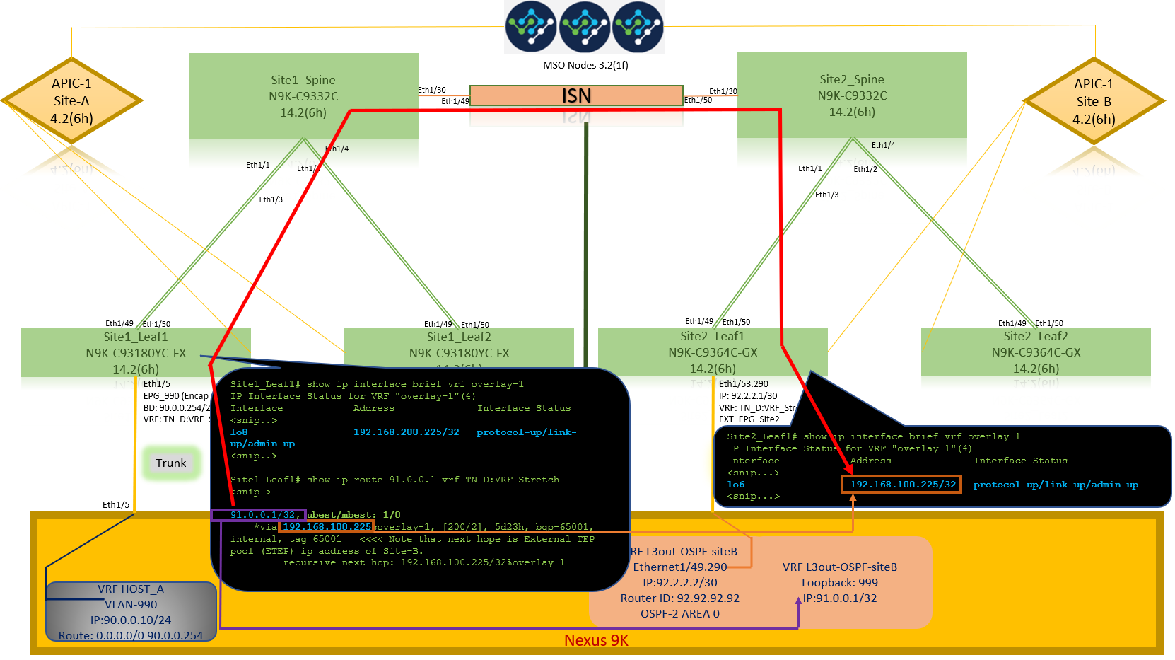
Site1_Leaf1# show ip route 92.2.2.2 vrf TN_D:VRF_Stretch
IP Route Table for VRF "TN_D:VRF_Stretch"
'*' denotes best ucast next-hop
'**' denotes best mcast next-hop
'[x/y]' denotes [preference/metric]
'%' in via output denotes VRF
92.2.2.0/30, ubest/mbest: 1/0
    *via 192.168.100.225%overlay-1, [200/0], 5d23h, bgp-65001, internal, tag 65001   <<<< Note that next hope is External TEP pool (ETEP) ip address of Site-B.
         recursive next hop: 192.168.100.225/32%overlay-1
Site1_Leaf1# show ip route 91.0.0.1 vrf TN_D:VRF_Stretch
IP Route Table for VRF "TN_D:VRF_Stretch"
'*' denotes best ucast next-hop
'**' denotes best mcast next-hop
'[x/y]' denotes [preference/metric]
'%' in via output denotes VRF
91.0.0.1/32, ubest/mbest: 1/0
    *via 192.168.100.225%overlay-1, [200/2], 5d23h, bgp-65001, internal, tag 65001   <<<< Note that next hope is External TEP pool (ETEP) ip address of Site-B.
         recursive next hop: 192.168.100.225/32%overlay-1
トラブルシュート
ここでは、設定のトラブルシューティングに使用できる情報を示します。
Site2_Leaf1
TN_D:VRF_stretchとOverlay-1間のBGPアドレスファミリルートインポート/エクスポート。
Site2_Leaf1# show system internal epm vrf TN_D:VRF_Stretch
+--------------------------------+--------+----------+----------+------+--------
               VRF                  Type    VRF vnid  Context ID Status Endpoint
                                                                          Count
+--------------------------------+--------+----------+----------+------+--------
  TN_D:VRF_Stretch                  Tenant   2686978    46         Up     1

Site2_Leaf1# show vrf TN_D:VRF_Stretch detail
VRF-Name: TN_D:VRF_Stretch, VRF-ID: 46, State: Up
    VPNID: unknown
    RD: 1101:2686978
    Max Routes: 0  Mid-Threshold: 0
    Table-ID: 0x8000002e, AF: IPv6, Fwd-ID: 0x8000002e, State: Up
    Table-ID: 0x0000002e, AF: IPv4, Fwd-ID: 0x0000002e, State: Up


Site2_Leaf1# vsh
Site2_Leaf1# show bgp vpnv4 unicast 91.0.0.1 vrf TN_D:VRF_Stretch
BGP routing table information for VRF overlay-1, address family VPNv4 Unicast
Route Distinguisher: 1101:2686978    (VRF TN_D:VRF_Stretch)
BGP routing table entry for 91.0.0.1/32, version 12 dest ptr 0xae6da350
Paths: (1 available, best #1)
Flags: (0x80c0002 00000000) on xmit-list, is not in urib, exported
  vpn: version 346, (0x100002) on xmit-list
Multipath: eBGP iBGP

  Advertised path-id 1, VPN AF advertised path-id 1
  Path type: redist 0x408 0x1 ref 0 adv path ref 2, path is valid, is best path
  AS-Path: NONE, path locally originated
    0.0.0.0 (metric 0) from 0.0.0.0 (10.0.72.64)
      Origin incomplete, MED 2, localpref 100, weight 32768
      Extcommunity:
          RT:65001:2686978
          VNID:2686978
          COST:pre-bestpath:162:110
  VRF advertise information:
  Path-id 1 not advertised to any peer
  VPN AF advertise information:
  Path-id 1 advertised to peers:
    10.0.72.65                                      <<


Site-B


      apic1# acidiag fnvread ID Pod ID Name Serial Number IP Address Role State LastUpdMsgId -------------------------------------------------------------------------------------------------------------- 101 1
      Site2_Spine FDO243207JH
       10.0.72.65/32 spine active 0 102 1 Site2_Leaf2 FDO24260FCH 10.0.72.66/32 leaf active 0 1101 1 Site2_Leaf1 FDO24260ECW 10.0.72.64/32 leaf active 0
Site2_Spine


Site2_Spine# vsh
Site2_Spine# show bgp vpnv4 unicast 91.0.0.1 vrf overlay-1 BGP routing table information for VRF overlay-1, address family VPNv4 Unicast <---------26bits---------> Route Distinguisher: 1101:2686978 <<<<<2686978 <--Binary--> 00001010010000000000000010 BGP routing table entry for 91.0.0.1/32, version 717 dest ptr 0xae643d0c Paths: (1 available, best #1) Flags: (0x000002 00000000) on xmit-list, is not in urib, is not in HW Multipath: eBGP iBGP Advertised path-id 1 Path type: internal 0x40000018 0x800040 ref 0 adv path ref 1, path is valid, is best path AS-Path: NONE, path sourced internal to AS 10.0.72.64 (metric 2) from 10.0.72.64 (10.0.72.64) <<< Site2_leaf1 IP Origin incomplete, MED 2, localpref 100, weight 0 Received label 0 Received path-id 1 Extcommunity: RT:65001:2686978 COST:pre-bestpath:168:3221225472 VNID:2686978 COST:pre-bestpath:162:110 Path-id 1 advertised to peers: 192.168.10.13 <<<< Site1_Spine mscp-etep IP.
Site1_Spine# show ip interface vrf overlay-1 <snip...>
lo12, Interface status: protocol-up/link-up/admin-up, iod: 89, mode: mscp-etep IP address: 192.168.10.13, IP subnet: 192.168.10.13/32 <<IP broadcast address: 255.255.255.255 IP primary address route-preference: 0, tag: 0
<snip...>
Site1_Spine


Site1_Spine# vsh
Site1_Spine# show bgp vpnv4 unicast 91.0.0.1 vrf overlay-1
BGP routing table information for VRF overlay-1, address family VPNv4 Unicast                                <---------26Bits-------->
Route Distinguisher: 1101:36241410                                                  <<<<<36241410<--binary-->10001010010000000000000010
BGP routing table entry for 91.0.0.1/32, version 533 dest ptr 0xae643dd4
Paths: (1 available, best #1)
Flags: (0x000002 00000000) on xmit-list, is not in urib, is not in HW
Multipath: eBGP iBGP
  Advertised path-id 1
  Path type: internal 0x40000018 0x880000 ref 0 adv path ref 1, path is valid, is best path, remote site path
  AS-Path: NONE, path sourced internal to AS
    192.168.100.225 (metric 20) from 192.168.11.13 (192.168.11.13)  <<< Site2_Leaf1 ETEP IP learn via Site2_Spine mcsp-etep address.
      Origin incomplete, MED 2, localpref 100, weight 0
      Received label 0
      Extcommunity:
          RT:65001:36241410
          SOO:65001:50331631
          COST:pre-bestpath:166:2684354560
          COST:pre-bestpath:168:3221225472
          VNID:2686978
          COST:pre-bestpath:162:110
      Originator: 10.0.72.64 Cluster list: 192.168.11.13 <<< Originator Site2_Leaf1 and Site2_Spine ips are listed here...
  Path-id 1 advertised to peers:
    10.0.80.64                         <<<< Site1_Leaf1 ip

Site2_Spine# show ip interface vrf overlay-1
<snip..>
lo13, Interface status: protocol-up/link-up/admin-up, iod: 92, mode: mscp-etep
  IP address: 192.168.11.13, IP subnet: 192.168.11.13/32
  IP broadcast address: 255.255.255.255
  IP primary address route-preference: 0, tag: 0
<snip..>

Site-B
apic1# acidiag fnvread
      ID   Pod ID                 Name    Serial Number         IP Address    Role        State   LastUpdMsgId
--------------------------------------------------------------------------------------------------------------
     101        1          Site2_Spine      FDO243207JH      10.0.72.65/32   spine         active   0
     102        1          Site2_Leaf2      FDO24260FCH      10.0.72.66/32    leaf         active   0
    1101        1          Site2_Leaf1      FDO24260ECW      10.0.72.64/32    leaf         active   0
サイト間フラグを確認します。
Site1_Spine# moquery -c bgpPeer -f 'bgp.Peer.addr*"192.168.11.13"'
Total Objects shown: 1
# bgp.Peer
addr             : 192.168.11.13/32
activePfxPeers   : 0
adminSt          : enabled
asn              : 65001
bgpCfgFailedBmp  :
bgpCfgFailedTs   : 00:00:00:00.000
bgpCfgState      : 0
childAction      :
ctrl             :
curPfxPeers      : 0
dn               : sys/bgp/inst/dom-overlay-1/peer-[192.168.11.13/32]
lcOwn            : local
maxCurPeers      : 0
maxPfxPeers      : 0
modTs            : 2021-09-13T11:58:26.395+00:00
monPolDn         :
name             :
passwdSet        : disabled
password         :
peerRole         : msite-speaker
privateASctrl    :
rn               : peer-[192.168.11.13/32] <<


         srcIf : lo12 status : totalPfxPeers : 0 ttl : 16 type : inter-site
        <<
ルート識別子エントリについて
サイト間フラグが設定されている場合、ローカルサイトのスパインはルートターゲットのローカルサイトIDを25ビットから設定できます。Site1は、RTでこのビットが設定されたBGPパスを取得すると、これがリモートサイトパスであることを認識します。
Site2_Leaf1# vsh
Site2_Leaf1# show bgp vpnv4 unicast 91.0.0.1 vrf TN_D:VRF_Stretch
BGP routing table information for VRF overlay-1, address family VPNv4 Unicast                                 <---------26Bits-------->
Route Distinguisher: 1101:2686978    (VRF TN_D:VRF_Stretch)                         <<<<<2686978 <--Binary--> 00001010010000000000000010
BGP routing table entry for 91.0.0.1/32, version 12 dest ptr 0xae6da350

Site1_Spine# vsh
Site1_Spine# show bgp vpnv4 unicast 91.0.0.1 vrf overlay-1
                                                                                                             <---------26Bits-------->
Route Distinguisher: 1101:36241410                                                  <<<<<36241410<--binary-->10001010010000000000000010
                                                                                                             ^^---26th bit set to 1 and with 25th bit value it become 10.
Site1のRTバイナリ値は、26番目のビットが1に設定されている点を除き、まったく同じであることに注意してください。10進数の値(青でマーク)があります。1101:36241410は、Site1で表示されるもので、Site1の内部リーフをインポートする必要があるものです。


Site1_Leaf1
Site1_Leaf1# show vrf TN_D:VRF_Stretch detail
VRF-Name: TN_D:VRF_Stretch, VRF-ID: 46, State: Up
VPNID: unknown
RD: 1101:2850817
Max Routes: 0 Mid-Threshold: 0
Table-ID: 0x8000002e, AF: IPv6, Fwd-ID: 0x8000002e, State: Up
Table-ID: 0x0000002e, AF: IPv4, Fwd-ID: 0x0000002e, State: Up

Site1_Leaf1# show bgp vpnv4 unicast 91.0.0.1 vrf overlay-1
BGP routing table information for VRF overlay-1, address family VPNv4 Unicast
Route Distinguisher: 1101:2850817    (VRF TN_D:VRF_Stretch)
BGP routing table entry for 91.0.0.1/32, version 17 dest ptr 0xadeda550
Paths: (1 available, best #1)
Flags: (0x08001a 00000000) on xmit-list, is in urib, is best urib route, is in HW
  vpn: version 357, (0x100002) on xmit-list
Multipath: eBGP iBGP
  Advertised path-id 1, VPN AF advertised path-id 1
  Path type: internal 0xc0000018 0x80040 ref 56506 adv path ref 2, path is valid, is best path, remote site path
             Imported from 1101:36241410:91.0.0.1/32
  AS-Path: NONE, path sourced internal to AS
    192.168.100.225 (metric 64) from 10.0.80.65 (192.168.10.13)
      Origin incomplete, MED 2, localpref 100, weight 0
      Received label 0
      Received path-id 1
      Extcommunity:
          RT:65001:36241410
          SOO:65001:50331631
          COST:pre-bestpath:166:2684354560
          COST:pre-bestpath:168:3221225472
          VNID:2686978
          COST:pre-bestpath:162:110
      Originator: 10.0.72.64 Cluster list: 192.168.10.13192.168.11.13             <<<< '10.0.72.64'='Site2_Leaf1' , '192.168.10.13'='Site1_Spine' , '192.168.11.13'='Site2_Spine'
  VRF advertise information:
  Path-id 1 not advertised to any peer
  VPN AF advertise information:
  Path-id 1 not advertised to any peer
<snip..>


Site1_Leaf1# show bgp vpnv4 unicast 91.0.0.1 vrf TN_D:VRF_Stretch
BGP routing table information for VRF overlay-1, address family VPNv4 Unicast
Route Distinguisher: 1101:2850817    (VRF TN_D:VRF_Stretch)
BGP routing table entry for 91.0.0.1/32, version 17 dest ptr 0xadeda550
Paths: (1 available, best #1)
Flags: (0x08001a 00000000) on xmit-list, is in urib, is best urib route, is in HW
  vpn: version 357, (0x100002) on xmit-listMultipath: eBGP iBGP
  Advertised path-id 1, VPN AF advertised path-id 1
  Path type: internal 0xc0000018 0x80040 ref 56506 adv path ref 2, path is valid, is best path, remote site path
             Imported from 1101:36241410:91.0.0.1/32
  AS-Path: NONE, path sourced internal to AS
    192.168.100.225 (metric 64) from 10.0.80.65 (192.168.10.13)
      Origin incomplete, MED 2, localpref 100, weight 0
      Received label 0
      Received path-id 1
      Extcommunity:
          RT:65001:36241410
          SOO:65001:50331631
          COST:pre-bestpath:166:2684354560
          COST:pre-bestpath:168:3221225472
          VNID:2686978
          COST:pre-bestpath:162:110
      Originator: 10.0.72.64 Cluster list: 192.168.10.13 192.168.11.13
  VRF advertise information:
  Path-id 1 not advertised to any peer
  VPN AF advertise information:
  Path-id 1 not advertised to any peer
したがって、「Site1_Leaf1」には、ネクストホップ「Site2_Leaf1」ETEPアドレス192.168.100.225のサブネット91.0.0.1/32のルートエントリがあります。
Site1_Leaf1# show ip route 91.0.0.1 vrf TN_D:VRF_Stretch
IP Route Table for VRF "TN_D:VRF_Stretch"
'*' denotes best ucast next-hop
'**' denotes best mcast next-hop
'[x/y]' denotes [preference/metric]
'%' in via output denotes VRF
91.0.0.1/32, ubest/mbest: 1/0
    *via 192.168.100.225%overlay-1, [200/2], 5d23h, bgp-65001, internal, tag 65001   <<<< Note that next hope is External TEP pool (ETEP) ip address of Site-B.
         recursive next hop: 192.168.100.225/32%overlay-1
Site-A Spineは、「Site2_Spine」mcsp-ETEPのBGPネイバーIPアドレスにルートマップを追加します。
トラフィックフローについて考えると、Site-Aエンドポイントが外部IPアドレスと通信する場合、パケットは送信元を「Site1_Leaf1」 TEPアドレスとしてカプセル化し、宛先を「Site2_Leaf」 IPアドレス192.168.100.225のETEPアドレスにすることができます。
ELAM(Site1_Spine)の確認
Site1_Spine# vsh_lc
module-1# debug platform internal roc elam asic 0
module-1(DBG-elam)# trigger reset
module-1(DBG-elam)# trigger init in-select 14 out-select 1
module-1(DBG-elam-insel14)# set inner ipv4 src_ip 90.0.0.10 dst_ip 91.0.0.1 next-protocol 1
module-1(DBG-elam-insel14)# start
module-1(DBG-elam-insel14)# status
 ELAM STATUS
===========
Asic 0 Slice 0 Status Armed
Asic 0 Slice 1 Status Armed
Asic 0 Slice 2 Status Armed
Asic 0 Slice 3 Status Armed
pod2-n9k# ping 91.0.0.1 vrf HOST_A source 90.0.0.10
PING 91.0.0.1 (91.0.0.1) from 90.0.0.10: 56 data bytes
64 bytes from 91.0.0.1: icmp_seq=0 ttl=252 time=1.015 ms
64 bytes from 91.0.0.1: icmp_seq=1 ttl=252 time=0.852 ms
64 bytes from 91.0.0.1: icmp_seq=2 ttl=252 time=0.859 ms
64 bytes from 91.0.0.1: icmp_seq=3 ttl=252 time=0.818 ms
64 bytes from 91.0.0.1: icmp_seq=4 ttl=252 time=0.778 ms
--- 91.0.0.1 ping statistics ---
5 packets transmitted, 5 packets received, 0.00% packet loss
round-trip min/avg/max = 0.778/0.864/1.015 ms
Site1_Spine ELAMがトリガーされます。Ereportは、Site-AリーフTEP IPアドレスのTEPアドレスと、Site2_Leaf1 ETEPアドレスへの宛先でパケットがカプセル化されていることを確認します。
module-1(DBG-elam-insel14)# status
 ELAM STATUS
===========
Asic 0 Slice 0 Status Armed
Asic 0 Slice 1 Status Armed
Asic 0 Slice 2 Status Triggered
Asic 0 Slice 3 Status Armed
module-1(DBG-elam-insel14)# ereport
Python available. Continue ELAM decode with LC Pkg
 ELAM REPORT

------------------------------------------------------------------------------------------------------------------------------------------------------
Outer L3 Header
------------------------------------------------------------------------------------------------------------------------------------------------------
L3 Type                       : IPv4
DSCP                          : 0
Don't Fragment Bit            : 0x0
TTL                           : 32
IP Protocol Number            : UDP
Destination IP                : 192.168.100.225       <<<'Site2_Leaf1' ETEP address
Source IP                     : 10.0.80.64            <<<'Site1_Leaf1' TEP address
------------------------------------------------------------------------------------------------------------------------------------------------------
Inner L3 Header
------------------------------------------------------------------------------------------------------------------------------------------------------
L3 Type                       : IPv4
DSCP                          : 0
Don't Fragment Bit            : 0x0
TTL                           : 254
IP Protocol Number            : ICMP
Destination IP                : 91.0.0.1
Source IP                     : 90.0.0.10
Site1_Spineルートマップの確認
Site-Aスパインがパケットを受信すると、coopやルートエントリを検索する代わりに「Site2_Leaf1」のETEPアドレスにリダイレクトできます。(サイトBにサイト間L3outがある場合、サイトAスパインは「infra-intersite-l3out」と呼ばれるルートマップを作成して、トラフィックをSite2_Leaf1のETEPにリダイレクトし、L3outから出ます)。
Site1_Spine# show bgp vpnv4 unicast neighbors 192.168.11.13 vrf overlay-1
BGP neighbor is 192.168.11.13,  remote AS 65001, ibgp link,  Peer index 4
  BGP version 4, remote router ID 192.168.11.13
  BGP state = Established, up for 10w4d
  Using loopback12 as update source for this peer
  Last read 00:00:03, hold time = 180, keepalive interval is 60 seconds
  Last written 00:00:03, keepalive timer expiry due 00:00:56
  Received 109631 messages, 0 notifications, 0 bytes in queue
  Sent 109278 messages, 0 notifications, 0 bytes in queue
  Connections established 1, dropped 0
  Last reset by us never, due to No error
  Last reset by peer never, due to No error
  Neighbor capabilities:
  Dynamic capability: advertised (mp, refresh, gr) received (mp, refresh, gr)
  Dynamic capability (old): advertised received
  Route refresh capability (new): advertised received
  Route refresh capability (old): advertised received
  4-Byte AS capability: advertised received
  Address family VPNv4 Unicast: advertised received
  Address family VPNv6 Unicast: advertised received
  Address family L2VPN EVPN: advertised received
  Graceful Restart capability: advertised (GR helper) received (GR helper)
  Graceful Restart Parameters:
  Address families advertised to peer:
  Address families received from peer:
  Forwarding state preserved by peer for:
  Restart time advertised by peer: 0 seconds
  Additional Paths capability: advertised received
  Additional Paths Capability Parameters:
  Send capability advertised to Peer for AF:
    L2VPN EVPN
  Receive capability advertised to Peer for AF:
    L2VPN EVPN
  Send capability received from Peer for AF:
    L2VPN EVPN
  Receive capability received from Peer for AF:
    L2VPN EVPN
  Additional Paths Capability Parameters for next session:
  [E] - Enable [D] - Disable
  Send Capability state for AF:
    VPNv4 Unicast[E] VPNv6 Unicast[E]
  Receive Capability state for AF:
    VPNv4 Unicast[E] VPNv6 Unicast[E]
  Extended Next Hop Encoding Capability: advertised received
  Receive IPv6 next hop encoding Capability for AF:
    IPv4 Unicast
  Message statistics:
                              Sent               Rcvd
  Opens:                         1                  1
  Notifications:                 0                  0
  Updates:                    1960               2317
  Keepalives:               107108             107088
  Route Refresh:               105                123
  Capability:                  104                102
  Total:                    109278             109631
  Total bytes:             2230365            2260031
  Bytes in queue:                0                  0
  For address family: VPNv4 Unicast
  BGP table version 533, neighbor version 533
  3 accepted paths consume 360 bytes of memory
  3 sent paths
  0 denied paths
  Community attribute sent to this neighbor
  Extended community attribute sent to this neighbor
  Third-party Nexthop will not be computed.
  Outbound route-map configured is infra-intersite-l3out, handle obtained   <<<< route-map to redirect traffic from Site-A to Site-B 'Site2_Leaf1' L3out
  For address family: VPNv6 Unicast
  BGP table version 241, neighbor version 241
  0 accepted paths consume 0 bytes of memory
  0 sent paths
  0 denied paths
  Community attribute sent to this neighbor
  Extended community attribute sent to this neighbor
  Third-party Nexthop will not be computed.
  Outbound route-map configured is infra-intersite-l3out, handle obtained
<snip...>

Site1_Spine# show route-map infra-intersite-l3out
route-map infra-intersite-l3out, permit, sequence 1
  Match clauses:
    ip next-hop prefix-lists: IPv4-Node-entry-102
    ipv6 next-hop prefix-lists: IPv6-Node-entry-102
  Set clauses:
    ip next-hop 192.168.200.226
route-map infra-intersite-l3out, permit, sequence 2   <<<< This route-map match if destination IP of packet 'Site1_Spine' TEP address then send to 'Site2_Leaf1' ETEP address.
  Match clauses:
    ip next-hop prefix-lists: IPv4-Node-entry-1101
    ipv6 next-hop prefix-lists: IPv6-Node-entry-1101
  Set clauses:
    ip next-hop 192.168.200.225
route-map infra-intersite-l3out, deny, sequence 999
  Match clauses:
    ip next-hop prefix-lists: infra_prefix_local_pteps_inexact
  Set clauses:
route-map infra-intersite-l3out, permit, sequence 1000
  Match clauses:
  Set clauses:
    ip next-hop unchanged

Site1_Spine# show ip prefix-list IPv4-Node-entry-1101
ip prefix-list IPv4-Node-entry-1101: 1 entries
   seq 1 permit 10.0.80.64/32  <<


           Site1_Spine# show ip prefix-list IPv4-Node-entry-102 ip prefix-list IPv4-Node-entry-102: 1 entries seq 1 permit 10.0.80.66/32 Site1_Spine# show ip prefix-list infra_prefix_local_pteps_inexact ip prefix-list infra_prefix_local_pteps_inexact: 1 entries seq 1 permit 10.0.0.0/16 le 32
更新履歴
| 改定 | 発行日 | コメント |
|---|---|---|
1.0 |
09-Dec-2021 |
初版 |
シスコ エンジニア提供
- Darshankumar MistryCisco TAC Engineer
シスコに問い合わせ
- サポート ケースをオープン

- (シスコ サービス契約が必要です。)
 フィードバック