スタンドアロンCatalyst 6500スイッチのCatalyst 6500 VSSへの移行
概要
このドキュメントでは、スタンドアロン Cisco Catalyst 6500 シリーズ スイッチの Cisco Catalyst 6500 Virtual Switching System への移行のための手順に関する情報を提供します。
注:このドキュメントでは、移行に必要な一般的な手順について説明します。厳密な手順は現状のスイッチ設定に基づくため、説明されている手順とは若干異なる可能性があります。
前提条件
要件
次の項目に関する知識があることが推奨されます。
-
Virtual Switching System(VSS)の概念に関する知識。詳細は、『Virtual Switching System について』を参照してください。
使用するコンポーネント
このドキュメントの情報は、Cisco IOS® ソフトウェア リリース 12.2(33)SXH1 以降が稼働する Supervisor VS-S720-10G-3C/XL が搭載された Cisco Catalyst 6500 シリーズ スイッチに基づくものです。
このドキュメントの情報は、特定のラボ環境にあるデバイスに基づいて作成されました。対象のネットワークが実稼働中である場合には、どのようなコマンドについても、その潜在的な影響について確実に理解しておく必要があります。
表記法
ドキュメント表記の詳細は、『シスコ テクニカル ティップスの表記法』を参照してください。
背景説明
Virtual Switching System(VSS)は、単一の論理エンティティへの 2 台の物理的なシャーシのクラスタ処理を効果的に実現する、Cisco Catalyst 6500 シリーズ スイッチの革新的な新機能です。このテクノロジーによって、ハイ アベイラビリティ、スケーラビリティまたはパフォーマンス、管理、および保守など、企業キャンパスとデータセンター展開の全領域における新たな拡張が可能になります。
VSS の現行の実装を使用すると、2 台の物理的な Cisco Catalyst 6500 シリーズ スイッチを、論理的に管理された単一のエンティティへ統合することができます。次の図は、VSS が有効になると、2 台の 6509 シャーシを単一の 18 スロット シャーシとして管理することが可能になる場合の概念を図示しています。

移行プロセス
ハードウェアおよびソフトウェアのサポート
VSS は Cisco Catalyst 6500 シリーズ スイッチでのみ使用可能なソフトウェア機能です。この機能をイネーブルにして設定するには、次が必要です。
| ハードウェア | VS-S720-10G-3C/XL |
| [ソフトウェア(Software)] | Cisco IOS ソフトウェア リリース 12.2(33)SXH1 以降 |
| モデル番号 | 説明 |
| WS-C6503-E | E シリーズ 3 スロット シャーシ |
| WS-C6504-E | E シリーズ 4 スロット シャーシ |
| WS-C6506 | 6 スロット シャーシ |
| WS-C6506-E | E シリーズ 6 スロット シャーシ |
| WS-C6509 | 9 スロット シャーシ |
| WS-C6509-E | E シリーズ 9 スロット シャーシ |
| WS-C6509-NEB-A | 9 スロット縦型 Network Equipment Building Standards(NEBS)シャーシ |
| WS-C6509-V-E | E シリーズ 9 スロット縦型シャーシ |
| WS-C6513 | 13 スロット シャーシ |
この表に、Cisco Virtual Switching System の初期リリースでサポートされるシャーシの全リストを示します。詳細については、『Cisco Catalyst 6500 Series Virtual Switching System(VSS)1440』を参照してください。
移行パス
この表では、可能な VSS への移行パスの一部を説明しています。このリストは提案に過ぎず、すべてを網羅しているわけではありません。
| 初期設定 | アップグレードが必要 | 最終設定 |
|---|---|---|
| WS-SUP720-3B スーパーバイザ搭載の 2 台の Cisco Catalyst 6500 シリーズ スイッチ |
ハードウェア アップグレード - スーパーバイザ VS-S720-10G-3C/XL ソフトウェア アップグレード - Cisco IOS 12.2(33)SXH1 以降 | VSS |
| VS-S720-10G-3C/XL スーパーバイザ搭載の 2 台の Cisco Catalyst 6500 シリーズ スイッチ |
ソフトウェア アップグレード:Cisco IOS 12.2(33)SXH1 以降 | VSS |
移行の概要
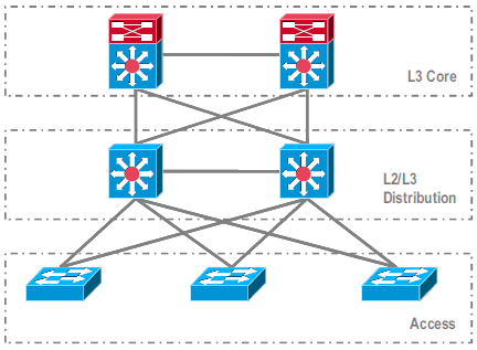
スタンドアロン環境での一般的な構成

レイヤ 3(L3)コアと L2/L3 ディストリビューションの間で実行される機能またはプロトコル:
-
IP ルーティング プロトコル
-
L3 ポート チャネルまたは IP ルーティングの等コスト マルチパス機能
L2/L3 ディストリビューションとアクセス レイヤの間で実行される機能またはプロトコル:
-
スパニング ツリー プロトコル
-
First Hop Routing Protocol(FHRP)
-
ポリシー:QoS、ACL
-
L2 トランク、VLAN、ポート チャネル
VSS への移行
これは段階的なプロセスで、このセクションでは各段階について説明しています。

コアとディストリビューション レイヤの間の移行手順:
-
MultiChassis EtherChannel(MEC)の設定
-
IP ルーティング設定の修正と不要になったコマンドの削除
ディストリビューションとアクセス レイヤの間の移行手順:
-
MEC の設定
-
スパニング ツリー プロトコルのイネーブル状態の維持
-
FHRP コマンドの修正
-
QoS と ACL のポリシーの MEC への移行(必要な場合)
-
L2 トランク設定の MEC への移行
移行プロセス手順
次のステップを実行します。
-
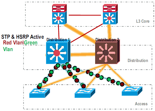
初期スタンドアロン設定では、一般的には、VLAN ロード シェアリングと HSRP 設定を使用して、トラフィックがディストリビューション スイッチ間でロード バランスされています。

-
HSRP と STP の設定を修正し、Distribution-1 がすべてのフローに対してアクティブで、隣接デバイスによってこの変更が検出され、すべてのトラフィックが Distribution-1 に送信されるようにします。

-
Distribution-2 の物理インターフェイスをシャットダウンして、ネットワークから切り離します。

.
Distribution-2 が完全にネットワークから削除されたら、本稼働トラフィックを中断することなく VSS モードへ変換することができます。
-
またインストールしていない場合は、新しいスーパーバイザ(VS-SUP720-10G)をインストールして、ステータスを確認します。
Distribution-2#show module
Mod Ports Card Type                              Model              Serial No.
--- ----- -------------------------------------- ------------------ -----------
  5    5  Supervisor Engine 720 10GE (Active)    VS-S720-10G        SAD104707BB
  9   48  CEF 720 48 port 10/100/1000mb Ethernet WS-X6748-GE-TX     SAL1020NGY3
-
VSS 互換の Cisco IOS ソフトウェアを sup-bootdisk: にコピーします。
Distribution-2#copy ftp: sup-bootdisk:
Address or name of remote host []? 172.16.85.150
Source filename []? s72033-ipservices_wan_vz.122-33.SXH1.bin
Destination filename [s72033-ipservices_wan_vz.122-33.SXH1.bin]?
Accessing ftp://172.16.85.150/s72033-ipservices_wan_vz.122-33.SXH1.bin...
-
bootvar を更新して、sup-bootdisk: にコピーされた Cisco IOS ソフトウェアをロードします。
Distribution-2(config)#boot system flash sup-bootdisk:s72033-ipservices_wan_vz.122-33.SXH1.bin -
Distribution-2 スイッチを VSS モードで稼働させるには、Virtual Switch Link(VSL)が必要です。VSL を形成するには、Distribution-1 と Distribution-2 の間の現行のポート チャネル リンクを使用できます。

-
仮想スイッチのアトリビュートを次のように設定します。
-
Virtual Switch Domain Number(ネットワーク内部で一意)
-
Virtual Switch Number(ドメイン内部で一意)
-
仮想スイッチリンク(VSL)
Distribution-2(config)#hostname VSS

VSS(config)#switch virtual domain 100

VSS(config-vs-domain)#switch 1


!--- After conversion Distribution-2 will be noted !--- as Switch 1 in VSS mode.

VSS(config-vs-domain)# exit
VSS(config)#interface port-channel 1
VSS(config-if)#switch virtual link 1

VSS(config-if)#interface TenG 5/4
VSS(config-if)#channel-group 1 mode on
VSS(config-if)#interface TenG 5/5
VSS(config-if)#channel-group 1 mode on
VSS(config-if)# ^Z
VSS#
-
-
Distribution-2 スイッチを VSS モードに変換します。
注:スイッチのコンソールから次のコマンドを発行します。
VSS#switch convert mode virtual

This command will convert all interface
names to naming convention "interface-type
switch-number/slot/port",
save the running config to startup-config and
reload the switch.
Do you want to proceed? [yes/no]: yes
Converting interface names
Building configuration...


!--- At this point the switch will reboot


!--- snippet of the console output

System detected Virtual Switch configuration...
 Interface TenGigabitEthernet 1/5/4 is member of
PortChannel 1
 Interface TenGigabitEthernet 1/5/5 is member of
PortChannel 1

!--- snippet of the console output

00:00:23: %PFREDUN-6-ACTIVE: Initializing as ACTIVE
processor for this switch

!--- snippet of the console output

00:00:28: %VSL_BRINGUP-6-MODULE_UP: VSL module in slot 5
switch 1 brought up
Initializing as Virtual Switch Active
-
Distribution-2 スイッチの VSS モードへの変換を確認します。
VSS#show switch virtual role

Switch  Switch Status  Preempt    Priority   Role     Session ID
        Number         Oper(Conf) Oper(Conf)          Local  Remote
-------------------------------------------------------------------
LOCAL    1     UP      FALSE(N)    110(110)  ACTIVE    0      0

In dual-active recovery mode: No
Distribution-2 スイッチが正常に変換され、VSS モードで動作しています。Distribution-1 の変換後、事前設定された手順も実行できます。ただし、事前設定は移行中のパケット損失量の削減に役立ちます。

-
次の手順を実行して、VSS Switch 1 を事前設定します。
-
Switch-1 のローカル インターフェイスを使用して MEC を設定します。Switch-2(現在の Distribution-1)のインターフェイスを VSS モードへの変換後に MEC に追加できます。
-
MEC を設定します。
-
インターフェイス設定を MEC へ移行します。
-
QoS と ACL のポリシーを MEC へ移行します。
設定の変更interface TenGigabitEthernet1/2/1 ip address 192.168.4.2 255.255.255.0 interface GigabitEthernet1/1/2 switchport switchport trunk encapsulation dot1q switchport trunk allowed vlan 10,20
ポート チャネルに対応するための隣接デバイスの設定!--- MEC to Core layer VSS(config)# int ten 1/2/1 VSS(config-if)# no ip address VSS(config-if)# interface po20 VSS(config-if)# ip address 192.168.4.2 255.255.255.0 VSS(config-if)# no shut VSS(config-if)# interface ten1/2/1 VSS(config-if)# channel-group 20 mode desirable !--- MEC to Access layer VSS(config-if)# interface po10 VSS(config-if)# switchport VSS(config-if)# switchport trunk encapsulation dot1q VSS(config-if)# switchport trunk allowed vlan 10,20 VSS(config-if)# no shut VSS(config-if)# interface gig1/1/2 VSS(config-if)# switchport VSS(config-if)# channel-group 10 mode desirable
VSS Switch-1 とその隣接デバイスの間の接続は、この時点でダウンしています。したがって、ポート チャネルは Distribution-1 を通過するトラフィック フローに干渉せずに設定されます。
!--- In Core layer devices

Core(config)# int gig 1/1
Core(config-if)# no ip address
Core(config-if)# int po20
Core(config-if)# ip address 192.168.4.1 255.255.255.0
Core(config-if)# no shut
Core(config-if)# int gig 1/1
Core(config-if)# channel-group 20 mode desirable
!--- In Access layer devices

Access(config)# int po10
Access(config-if)# switchport
Access(config-if)# switchport trunk encapsulation dot1q
Access(config-if)# switchport trunk
Access(config-if)# no shut
Access(config-if)# int gig 1/1
Access(config-if)# channel-group 10 mode desirable
-
-
VSS では、アクティブ側とスタンバイ側のどちらのシャーシによっても、アクティブ側のシャーシに焼き付けられた MAC アドレスと VLAN IP アドレスが使用されます。HSRP は不要になります。
-
HSRP 仮想 IP アドレスを VLAN インターフェイスに移行します。
-
VLAN インターフェイスから HSRP 設定を削除します。
設定の変更interface Vlan10 ip address 10.1.1.2 255.255.255.0 standby 10 ip 10.1.1.1 standby 10 priority 110 ! interface Vlan20 ip address 20.1.1.2 255.255.255.0 standby 20 ip 20.1.1.1 standby 20 priority 110 !
VSS(config)# interface Vlan10
VSS(config-if)# no standby 10 ip 10.1.1.1
VSS(config-if)# no standby 10 priority 110
VSS(config-if)# ip address 10.1.1.1 255.255.255.0
VSS(config-if)# interface Vlan20
VSS(config-if)# no standby 20 ip 20.1.1.1
VSS(config-if)# no standby 20 priority 110
VSS(config-if)# ip address 20.1.1.1 255.255.255.0
注:エンドデバイスは、引き続きARPエントリを初期HSRP MACアドレスにポイントします。これらのエントリにタイム アウトが発生するか、別の ARP がキャッシュをアップデートするために送信されるまで、接続の一部が失われます。
-
-
使用される IP ルーティング プロトコルに NSF-SSO 機能をイネーブルにします。VSS ではルーティング設定が簡素化されるため、一部の network 設定文が不要になります。したがって、これらを削除できます。
VSS Switch-1
コアVSS#show running-config | begin ospf router ospf 1 log-adjacency-changes network 10.1.1.0 0.0.0.255 area 0 network 20.1.1.0 0.0.0.255 area 0 network 192.168.4.0 0.0.0.255 area 0 network 192.168.5.0 0.0.0.255 area 0 !--- rest of output elided !--- Previous L3 interfaces are merged as MEC, hence some routing statements are no longer required. VSS(config)# router ospf 1 VSS(config-router)# nsf VSS(config-router)# no network 192.168.5.0 0.0.0.255 area 0
Core#show running-config | begin ospf
router ospf 1
 log-adjacency-changes
 network 192.168.4.0 0.0.0.255 area 0
 network 192.168.5.0 0.0.0.255 area 0

!--- rest of output elided


!--- Previous L3 interfaces are merged as MEC, hence some routing statements are no longer required.


Core(config)# router ospf 1
Core(config-router)# nsf
Core(config-router)# no network 192.168.5.0 0.0.0.255 area 0
-
STP 設定を修正して、VSS Switch-1 がすべての VLAN のルート(root)になるようにします。
-
-
VSS Switch-1 設定と接続を確認します。
-
VSS Switch-1 インターフェイスをイネーブルにします。
-
アクセス レイヤ デバイスへの L2 接続を確認します。
-
コア レイヤ デバイスへの L3 接続を確認します。

-
-
VSS Switch-1 接続の確認後、Distribution-1 のインターフェイスをシャットダウンし、トラフィックを VSS にスイッチングします。

-
Distribution-1 スイッチ上で変換手順を繰り返し、優先する VSS スタンバイ モードにします。
Distribution-1(config)#hostname VSS

VSS(config)#switch virtual domain 100

VSS(config-vs-domain)#switch 2


!--- After conversion Distribution-1 will be noted !--- as Switch 2 in VSS mode.

VSS(config-vs-domain)# exit
VSS(config)#interface port-channel 2
VSS(config-if)#switch virtual link 2

VSS(config-if)#interface TenG 5/4
VSS(config-if)#channel-group 2 mode on
VSS(config-if)#interface TenG 5/5
VSS(config-if)#channel-group 2 mode on
VSS(config-if)# ^Z
VSS#

VSS#switch convert mode virtual

This command will convert all interface
names to naming convention "interface-type
switch-number/slot/port",
save the running config to startup-config and
reload the switch.
Do you want to proceed? [yes/no]: yes
Converting interface names
Building configuration...


!--- At this point the switch will reboot


!--- snippet of the console output

System detected Virtual Switch configuration...
 Interface TenGigabitEthernet 2/5/4 is member of
PortChannel 2
 Interface TenGigabitEthernet 2/5/5 is member of
PortChannel 2

!--- snippet of the console output

00:00:23: %PFREDUN-6-ACTIVE: Initializing as ACTIVE
processor for this switch

!--- snippet of the console output

00:00:28: %VSL_BRINGUP-6-MODULE_UP: VSL module in slot 5
switch 2 brought up
Initializing as Virtual Switch Standby
-
VSS スタンバイ スイッチのブートアップ後、VSS アクティブ設定が自動的に VSS スタンバイへ同期されます。ブートアップ時、VSS スタンバイ(Switch-2)のインターフェイスはシャットダウン状態になります。

-
仮想スイッチの設定を完了します。
注:この最後の重要な手順は、初回の変換にのみ適用されます。スイッチの変換を行った後や、すでに部分的な変換を行った後には、このコマンドは使用できません。スイッチが変換または部分的に変換された場合は、エラー メッセージが生成されます。
11:27:30: %PM-SP-4-ERR_DISABLE: channel-misconfig error detected
on Po110, putting Gi9/2 in err-disable state
このコマンドを発行して、アクティブ仮想スイッチ上で自動的にスタンバイ仮想スイッチ設定を構成することができます。
VSS#switch accept mode virtual

This command will bring in all VSL configurations from the standby
switch and populate it into the running configuration.
In addition the startup configurations will be updated with the
new merged configurations.
Do you want proceed? [yes/no]: yes
Merging the standby VSL configuration. . .
Building configuration...
注:設定が自動的にマージされると、Cisco IOSソフトウェアリリース12.2 SXIではswitch accept mode virtualコマンドは不要になります。
-
Switch-2 インターフェイスを MEC へ追加します。
- VSS
!--- To Core layer

VSS(config)# interface range tengig 1/2/1, tengig2/2/1
VSS(config-if-range)# channel-group 20 mode desirable
VSS(config-if-range)# no shut


!--- To Access layer

VSS(config)# interface range gig 1/1/2, gig 2/1/2
VSS(config-if-range)# switchport
VSS(config-if-range)# channel-group 10 mode desirable
VSS(config-if-range)# no shut
- VSS ネイバー:コア
Core(config)# interface range gig 1/1, gig 1/2
Core(config-if-range)# channel-group 20 mode desirable
Core(config-if-range)# no shut
- VSS ネイバー:アクセス
Access(config)# interface range gig 1/1, gig 1/2
Access(config-if-range)# channel-group 10 mode desirable
Access(config-if-range)# no shut
VSS への移行が完了しました。この時点で、VSS のどちらのスイッチも稼働し、トラフィックはすべてのアップリンク インターフェイスでロード バランスされています。

- VSS
関連情報
更新履歴
| 改定 | 発行日 | コメント |
|---|---|---|
1.0 |
01-Dec-2013 |
初版 |


 フィードバック