Cisco NX-OS Interfaces コンフィギュレーション Release 4.0
偏向のない言語
この製品のマニュアルセットは、偏向のない言語を使用するように配慮されています。このマニュアルセットでの偏向のない言語とは、年齢、障害、性別、人種的アイデンティティ、民族的アイデンティティ、性的指向、社会経済的地位、およびインターセクショナリティに基づく差別を意味しない言語として定義されています。製品ソフトウェアのユーザーインターフェイスにハードコードされている言語、RFP のドキュメントに基づいて使用されている言語、または参照されているサードパーティ製品で使用されている言語によりドキュメントに例外が存在する場合があります。シスコのインクルーシブランゲージに対する取り組みの詳細は、こちらをご覧ください。
翻訳について
このドキュメントは、米国シスコ発行ドキュメントの参考和訳です。リンク情報につきましては、日本語版掲載時点で、英語版にアップデートがあり、リンク先のページが移動/変更されている場合がありますことをご了承ください。あくまでも参考和訳となりますので、正式な内容については米国サイトのドキュメントを参照ください。
- Updated:
- 2017年6月2日
章のタイトル: レイヤ 3 インターフェイスの設定
レイヤ 3 インターフェイスの設定
この章では、レイヤ 3 インターフェイスを設定する手順について説明します。
•![]() 「関連項目」
「関連項目」
レイヤ 3 インターフェイスについて
レイヤ 3 インターフェイスは、IPv4 および IPv6 パケットをスタティックまたはダイナミック ルーティング プロトコルを使って別のデバイスに転送します。レイヤ 2 トラフィックの IP ルーティングおよび内部 VLAN ルーティングにはレイヤ 3 ルーティングが使用できます。
ルーテッド インターフェイス
ポートをレイヤ 2 インターフェイスまたはレイヤ 3 インターフェイスとして設定できます。ルーテッド インターフェイスは、IP トラフィックを他のデバイスにルーティングできる物理ポートです。ルーテッド インターフェイスはレイヤ 3 インターフェイスだけで、Spanning Tree Protocol(STP; スパニング ツリー プロトコル)などのレイヤ 2 プロトコルはサポートしません。
すべてのイーサネット ポートは、デフォルトでルーテッド インターフェイスです。このデフォルト動作を変更するには、CLI(コマンドライン インターフェイス)セットアップ スクリプトまたは system default switchport コマンドを使用します。
ポートに IP アドレスを割り当て、ルーティングをイネーブルにし、このルーテッド インターフェイスにルーティング プロトコル特性を割り当てることができます。
ルーテッド インターフェイスからレイヤ 3 ポート チャネルも作成できます。ポート チャネルの詳細については、 第 5 章「ポート チャネルの設定」 を参照してください。
ルーテッド インターフェイスおよびサブインターフェイスは、指数関数的に減少するレート カウンタをサポートします。NX-OS はこれらの平均カウンタを用いて次の統計情報を追跡します。
サブインターフェイス
レイヤ 3 インターフェイスとして設定した親インターフェイスに仮想サブインターフェイスを作成できます。親インターフェイスは物理ポートでもポート チャネルでもかまいません。
親インターフェイスはサブインターフェイスによって複数の仮想インターフェイスに分割されます。これらの仮想インターフェイスに IP アドレスやダイナミック ルーティング プロトコルなど固有のレイヤ 3 パラメータを割り当てることができます。各サブインターフェイスの IP アドレスは、親インターフェイスの他のサブインターフェイスのサブネットとは異なります。
サブインターフェイスの名前は、親インターフェイスの名前(たとえば Ethernet 2/1)+ ピリオド(.)+そのインターフェイス独自の番号です。たとえば、イーサネット インターフェイス 2/1 に Ethernet 2/1.1 というサブインターフェイスを作成できます。この場合、.1 はそのサブインターフェイスを表します。
NX-OS では、親インターフェイスの場合にサブインターフェイスがイネーブルになります。サブインターフェイスは、親インターフェイスには関係なくシャットダウンできます。親インターフェイスをシャットダウンすると、関連するサブインターフェイスもすべてシャットダウンされます。
サブインターフェイスを使用すると、親インターフェイスがサポートするそれぞれの Virtual Local Area Network(VLAN; バーチャル LAN)に独自のレイヤ 3 インターフェイスを実現できます。この場合、親インターフェイスは別のデバイスのレイヤ 2 トランキング ポートに接続します。サブインターフェイスを設定したら 802.1Q トランキングを使って VLAN ID に関連付けます。
図4-1 に、インターフェイス E 2/1 のルータ B に接続するスイッチのトランキング ポートを示します。このインターフェイスには 3 つのサブインターフェイスがあり、トランキング ポートに接続する 3 つの VLAN にそれぞれ関連付けられています。

VLAN の詳細については、『 Cisco NX-OS Layer 2 Switching Configuration Guide, Release 4.0 』を参照してください。
VLAN インターフェイス
VLAN インターフェイスまたは Switch Virtual Interface(SVI; スイッチ仮想インターフェイス)は仮想のルーテッド インターフェイスで、デバイスの VLAN を同じデバイスのレイヤ 3 ルータ エンジンに接続します。1 つの VLAN には 1 つの VLAN インターフェイスだけを関連付けできますが、VLAN 同士をルーティングする場合や管理 Virtual Routing and Forwarding(VRF)以外の VRF インスタンスを経由してデバイスを IP ホスト接続する場合以外は、VLAN に VLAN インターフェイスを設定する必要があります。VLAN インターフェイスの作成をイネーブルにすると、デフォルト VLAN(VLAN 1)に VLAN インターフェイスが作成され、リモート スイッチ管理が許可されます。

(注) VLAN 1 の VLAN インターフェイスは削除できません。
VLAN インターフェイスをルーティングするには、トラフィックをルーティングする VLAN ごとに VLAN インターフェイスを作成し、そのVLAN インターフェイスに IP アドレスを割り当ててレイヤ 3 内部 VLAN ルーティングを実現します。IP アドレスと IP ルーティングの詳細については、『 Cisco NX-OS Unicast Routing Configuration Guide, Release 4.0 』を参照してください。
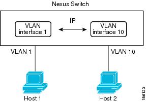
図4-2 に、2 つの VLAN に 2 つのホストが接続しているデバイスを示します。VLAN ごとに VLAN インターフェイスを設定し、VLAN 間の IP ルーティングを使ってホスト 1 とホスト 2 を通信させることができます。VLAN 1 は VLAN インターフェイスのレイヤ 3 で、VLA 10 は VLAN インターフェイス 10 のレイヤ 3 で通信します。
図4-2 VLAN インターフェイスに接続した 2 つの VLAN
ループバック インターフェイス
ループバック インターフェイスは、常にアップ状態にある単独のエンドポイントを持つ仮想インターフェイスです。ループバック インターフェイスを通過するパケットはこのインターフェイスでただちに受信されます。ループバック インターフェイスは物理インターフェイスをエミュレートします。Virtual Device Context(VDC)ごとに 1024 のループバック インターフェイスが設定できます。VDC には 0 ~ 1023 の番号が付いています。
ループバック インターフェイスを使用すると、パフォーマンスの分析、テスト、ローカル通信が実行できます。ループバック インターフェイスは、ルーティング プロトコル セッションの終端アドレスとして設定することができます。ループバックをこのように設定すると、アウトバウンド インターフェイスの一部がダウンしている場合でもルーティング プロトコル セッションはアップしたままです。
トンネル インターフェイス
Cisco NX-OS は、IP トンネルとしてトンネル インターフェイスをサポートします。IP トンネルを使うと、同じレイヤまたは上位レイヤ プロトコルをカプセル化して、2 台のルータ間で作成されたトンネルを通じて IP の結果を転送できます。IP トンネルの詳細については、 第 6 章「IP トンネルの設定」 を参照してください。
ハイ アベイラビリティ
レイヤ 3 インターフェイスは、ステートフル再起動とステートレス再起動をサポートします。切り替え後、NX-OS は切り替え後の実行時設定を適用します。
ハイ アベイラビリティの詳細については、『 Cisco NX-OS High Availability and Redundancy Guide, Release 4.0 』を参照してください。
バーチャライゼーション サポート
レイヤ 3 インターフェイスは、VRF インスタンスをサポートします。VRF は VDC 内に存在します。VDC や VRF を特別に設定しないかぎり、デフォルトでは、NX-OS のデフォルトの VDC およびデフォルトの VRF が使用されます。ある VDC に設定されたレイヤ 3 論理インターフェイス(VLAN インターフェイス、ループバック)は、同じ番号を持つ別の VDC に設定されたレイヤ 3 論理インターフェイスとは区別されます。たとえば、VDC 1 のループバック 0 は VDC のループバック 0 とは異なります。
VDC ごとに最大 1024 のループバック インターフェイスを設定できます。
このインターフェイスは VRF に関連付けることができます。VLAN インターフェイスの場合、VLAN と同じ VDC に設定する必要があります。
VDC については『 Cisco NX-OS Virtual Device Context Configuration Guide, Release 4.0 』を、VRF でのインターフェイスの設定については『 Cisco NX-OS Unicast Routing Configuration Guide, Release 4.0 』を参照してください。
(注) そのインターフェイスに IP アドレスを設定する前に、インターフェイスに VRF を割り当てる必要があります。
レイヤ 3 インターフェイスのライセンス要件
|
|
|
|---|---|
レイヤ 3 インターフェイスにライセンスは必要ありません。ライセンス パッケージに含まれていない機能は Cisco NX-OS システム イメージに組み込まれており、無料で提供されます。NX-OS ライセンス スキームの詳細については、『 Cisco NX-OS Licensing Guide 』を参照してください。 |
ライセンス 3 インターフェイスの前提条件
ライセンス 3 インターフェイスには次の前提条件があります。
•![]() Advanced Services ライセンスをインストールしており、VDC を設定する場合は、該当する VDC を開始している(『 Cisco NX-OS Virtual Device Context Configuration Guide, Release 4.0 』を参照してください)。
Advanced Services ライセンスをインストールしており、VDC を設定する場合は、該当する VDC を開始している(『 Cisco NX-OS Virtual Device Context Configuration Guide, Release 4.0 』を参照してください)。
•![]() IP アドレッシングおよび基本設定を熟知している。IPアドレッシングの詳細については、『 Cisco NX-OS Unicast Routing Configuration Guide, Release 4.0 』を参照してください。
IP アドレッシングおよび基本設定を熟知している。IPアドレッシングの詳細については、『 Cisco NX-OS Unicast Routing Configuration Guide, Release 4.0 』を参照してください。
注意事項と制限
レイヤ 3 インターフェイスの設定には次の注意事項と制限があります。
•![]() レイヤ 3 インターフェイスをレイヤ 2 インターフェイスに変更する場合、NX-OS はインターフェイスをシャットダウンしてインターフェイスを再度イネーブルにし、レイヤ 3 固有の設定をすべて削除します。
レイヤ 3 インターフェイスをレイヤ 2 インターフェイスに変更する場合、NX-OS はインターフェイスをシャットダウンしてインターフェイスを再度イネーブルにし、レイヤ 3 固有の設定をすべて削除します。
•![]() レイヤ 2 インターフェイスをレイヤ 3 インターフェイスに変更する場合、NX-OS はインターフェイスをシャットダウンしてインターフェイスを再度イネーブルにし、レイヤ 2 固有の設定をすべて削除します。
レイヤ 2 インターフェイスをレイヤ 3 インターフェイスに変更する場合、NX-OS はインターフェイスをシャットダウンしてインターフェイスを再度イネーブルにし、レイヤ 2 固有の設定をすべて削除します。
(注) Cisco IOS CLI を熟知している場合は、この機能の NX-OS コマンドと、使用する Cisco IOS コマンドが異なる場合もある点に注意してください。
レイヤ 3 インターフェイスの設定
ルーテッド インターフェイスの設定
作業の前に
ステップの概要
2.![]() interface ethernet slot/port
interface ethernet slot/port
4.![]() ip address ip-address/length
ip address ip-address/length
または
ipv6 address ipv6-address/length
ステップの詳細
インターフェイス メディアを point-to-point(p2p; ポイントツーポイント)またはブロードキャストに設定するには、 medium コマンドを使用します。
|
|
|
|---|---|
|
|
レイヤ 3 インターフェイスをレイヤ 2 インターフェイスに変換するには、 switchport コマンドを使用します。
|
|
|
|---|---|
|
|
インターフェイスをレイヤ 2 インターフェイスとして設定し、このインターフェイス上のレイヤ 3 固有の設定を削除します。 |
switch(config)# i nterface ethernet 2/1
switch(config-if)# no switchport
switch(config-if)# ip address 192.0.2.1/8
switch(config-if)# copy running-config startup-config
サブインターフェイスの設定
ルーテッド インターフェイスまたはルーテッド インターフェイスで作成したポート チャネルに 1 つまたは複数のサブインターフェイスを設定できます。
作業の前に
親インターフェイスをルーテッド インターフェイスとして設定します。「ルーテッド インターフェイスの設定」を参照してください。
このポートチャネル上にサブインターフェイスを作成するには、ポートチャネル インターフェイスを作成します( ポート チャネルの設定を参照)。
ステップの概要
2.![]() interface ethernet slot/port.number
interface ethernet slot/port.number
3.![]() ip address ip-address/length
ip address ip-address/length
または
ipv6 address ipv6-address/length
ステップの詳細
switch(config)# i nterface ethernet 2/1.1
switch(config-if)# ip address 192.0.2.1/8
switch(config-if)# encapsulation dot1Q 33
switch(config-if)# copy running-config startup-config
インターフェイスでの帯域幅の設定
ルーテッド インターフェイス、ポート チャネル、またはサブインターフェイスに帯域幅を設定できます。上位レイヤ プロトコルは帯域幅パラメータを使用してパス コストを計算します。サブインターフェイスの帯域幅は、次のいずれかの方法で設定できます。
•![]() 明示的 ― サブインターフェイスの帯域幅を直接設定します。
明示的 ― サブインターフェイスの帯域幅を直接設定します。
•![]() 継承 ― サブインターフェイスが親インターフェイスを継承するように帯域幅を設定します。特定の値の場合と親インターフェイスの帯域幅の場合があります。
継承 ― サブインターフェイスが親インターフェイスを継承するように帯域幅を設定します。特定の値の場合と親インターフェイスの帯域幅の場合があります。
サブインターフェイスの帯域幅を設定しない場合、または親インターフェイスの帯域幅を継承しない場合、サブインターフェイスの帯域幅は次の方法で決定されます。
•![]() 親インターフェイスがアップしている場合、サブインターフェイスの帯域幅は親インターフェイスの動作速度と同じです。ポートの場合、サブインターフェイスの帯域幅は設定されているリンク速度またはネゴシエート対象のリンク速度です。ポート チャネルの場合、サブインターフェイスの帯域幅は、ポート チャネルの各メンバのリンク速度の集合です。
親インターフェイスがアップしている場合、サブインターフェイスの帯域幅は親インターフェイスの動作速度と同じです。ポートの場合、サブインターフェイスの帯域幅は設定されているリンク速度またはネゴシエート対象のリンク速度です。ポート チャネルの場合、サブインターフェイスの帯域幅は、ポート チャネルの各メンバのリンク速度の集合です。
•![]() 親インターフェイスがダウンしている場合、サブインターフェイスの帯域幅は親インターフェイスのタイプによって異なります。
親インターフェイスがダウンしている場合、サブインターフェイスの帯域幅は親インターフェイスのタイプによって異なります。
–![]() ポートチャネル サブインターフェイスの場合、サブインターフェイスの帯域幅は 100 Mbps です。
ポートチャネル サブインターフェイスの場合、サブインターフェイスの帯域幅は 100 Mbps です。
–![]() 1 Gbps イーサネット ポートの場合、サブインターフェイスの帯域幅は 1 Gbps です。
1 Gbps イーサネット ポートの場合、サブインターフェイスの帯域幅は 1 Gbps です。
–![]() 10 Gbps イーサネット ポートの場合、サブインターフェイスの帯域幅は 10 Gbps です。
10 Gbps イーサネット ポートの場合、サブインターフェイスの帯域幅は 10 Gbps です。
インターフェイスの帯域幅を設定するには、インターフェイス モードで次のコマンドを使用します。
|
|
|
|---|---|
|
|
サブインターフェイスを設定して親インターフェイスの帯域幅を継承させるには、インターフェイス モードで次のコマンドを使用します。
|
|
|
|---|---|
|
|
このインターフェイスのすべてのサブインターフェイスが設定した帯域幅を継承するように設定します。値を設定しない場合、サブインターフェイスは親インターフェイスの帯域幅を継承します。有効値の範囲は 1 ~ 10,000,000 キロバイトです。 |
VLAN インターフェイスの設定
作業の前に
ステップの概要
4.![]() ip address ip-address/length
ip address ip-address/length
または
ipv6 address ipv6-address/length
ステップの詳細
switch(config)# feature interface-vlan
switch(config)# in terface vlan 10
switch(config-if)# ip address 192.0.2.1/8
switch(config-if)# copy running-config startup-config
ループバック インターフェイスの設定
作業の前に
ステップの概要
2.![]() interface loopback instance
interface loopback instance
3.![]() ipv4 address ip-address
ipv4 address ip-address
または
ipv6 address
ステップの詳細
次に、ループバック インターフェイスを作成する例を示します。
switch(config)# in terface loopback 0
switch(config-if)# ip address 192.0.2.100/8
switch(config-if)# copy running-config startup-config
インターフェイスの VRF への割り当て
作業の前に
ステップの概要
2.![]() interface interface-type number
interface interface-type number
4.![]() ip-address ip-prefix/length
ip-address ip-prefix/length
ステップの詳細
次に、レイヤ 3 インターフェイスに VRF を追加する例を示します。
switch(config)# interface loopback 0
switch(config-if)# vrf member RemoteOfficeVRF
switch(config-if)# ip address 209.0.2.1/16
switch(config-if)# copy running-config startup-config
レイヤ 3 インターフェイスの設定の確認
レイヤ 3 の設定情報を確認するには、次のコマンドを使用します。
レイヤ 3 インターフェイス統計情報の表示
レイヤ 3 インターフェイスの統計情報を表示するには、次のコマンドを使用します。
レイヤ 3 インターフェイスの設定例
次に、イーサネット サブインターフェイスを設定する例を示します。
次に、ループバック インターフェイスを設定する例を示します。
関連項目
レイヤ 3 インターフェイスの詳細については、次の項目を参照してください。
•![]() 『 Cisco NX-OS Unicast Routing Configuration Guide, Release 4.0 』
『 Cisco NX-OS Unicast Routing Configuration Guide, Release 4.0 』
デフォルト設定
表4-1 に、レイヤ 3 インターフェイス パラメータのデフォルト設定を示します。
|
|
|
|---|---|
その他の参考資料
レイヤ 3 インターフェイスの実装に関する追加情報については、次のセクションを参照してください。
•![]() 「関連資料」
「関連資料」
•![]() 「MIB」
「MIB」
•![]() 「標準」
「標準」
関連資料
|
|
|
|---|---|
『 Cisco NX-OS Unicast Routing Configuration Guide, Release 4.0 』の「Configuring IP」の章 |
|
『 Cisco NX-OS Layer 2 Switching Configuration Guide, Release 4.0 』の「Configuring VLANs」の章 |
MIB
|
|
|
|---|---|
次の URL で MIB にアクセスしてダウンロードします。 http://www.cisco.com/public/sw-center/netmgmt/cmtk/mibs.shtml |
標準
|
|
|
|---|---|
この機能でサポートする新しい標準や変更された標準はありません。現在サポートされている標準のうち、この機能で変更されたものはありません。 |
 フィードバック