소개
이 문서에서는 다양한 유형의 인라인 집합을 사용하여 투명 모드에서 FTD를 구축할 때 이벤트가 표시되는 방법에 대해 설명합니다.
목표
FTD가 인라인 집합 컨피그레이션을 사용하여 투명 모드에서 구축될 때 FMC에서 연결 이벤트의 동작을 명확하게 하기 위해
토폴로지
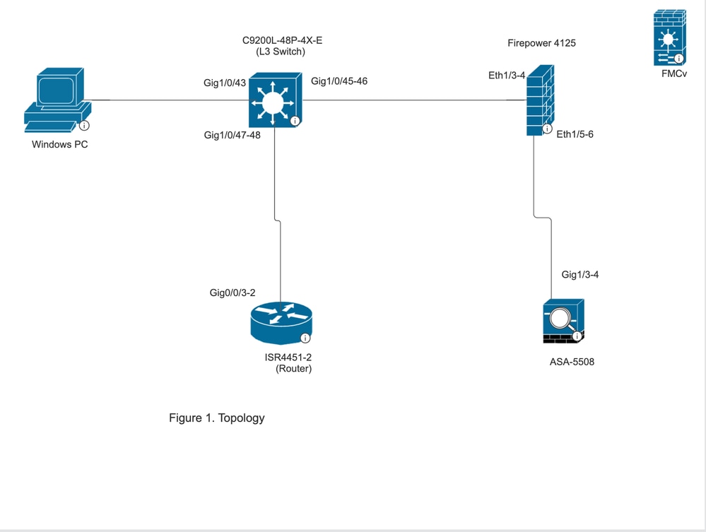
사용되는 구성 요소
- PC-가상 머신
- C9200L-48P-4X-E (L3 스위치)
- Firepower 4125 | 7.6
- FMCv | 7.6
- ASA 5508
- ISR4451-2(라우터)
기본 시나리오
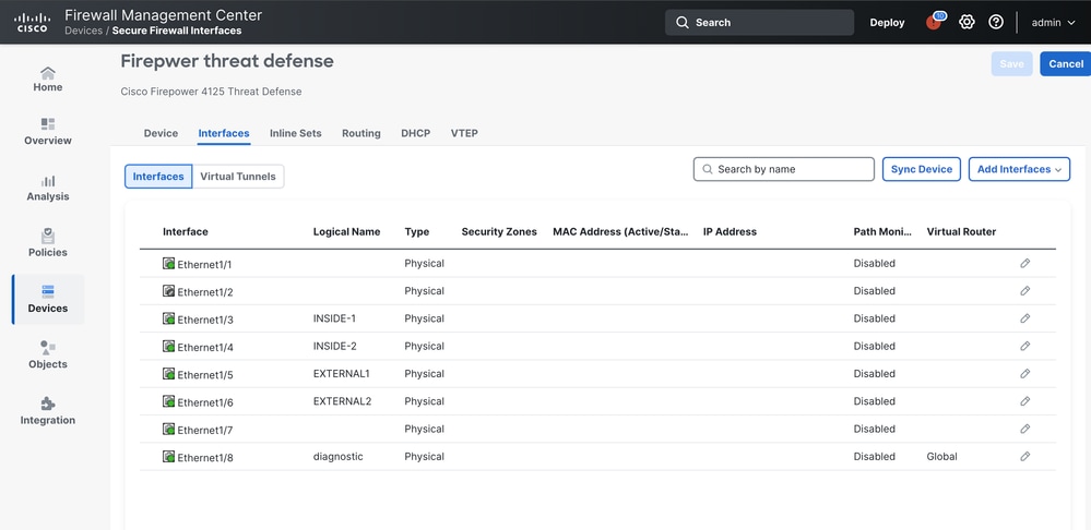
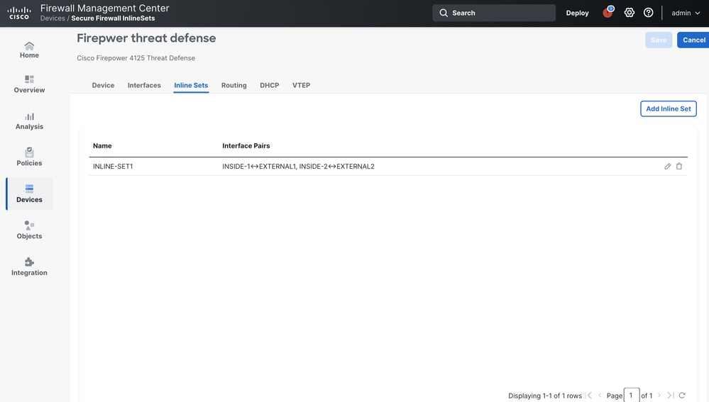
firepower 4125에서 하나의 인라인 집합 컨피그레이션에 두 개의 선택된 인터페이스 쌍이 포함된 경우
이더넷 1/3(INSIDE-1)
이더넷 1/5(외부1)
이더넷 1/4(내부-2)
이더넷 1/6(외부2)
구성 개요
L3 스위치
포트 채널 2(Gig 1/0/45-46)
ASA 5508
포트 채널 2(Gig 1/3-4)
ASA는 One arm 모드로 구축됩니다. 즉, 트래픽이 포트 채널 2인 동일한 포트 채널을 통해 ASA로 들어오고 나갑니다.
포트 채널은 ASA에서 구성되고 스위치에서 두 채널 간의 트래픽을 로드 밸런싱합니다.
Firepower 4125는 FMCv에 등록됩니다.
FMCv
구성
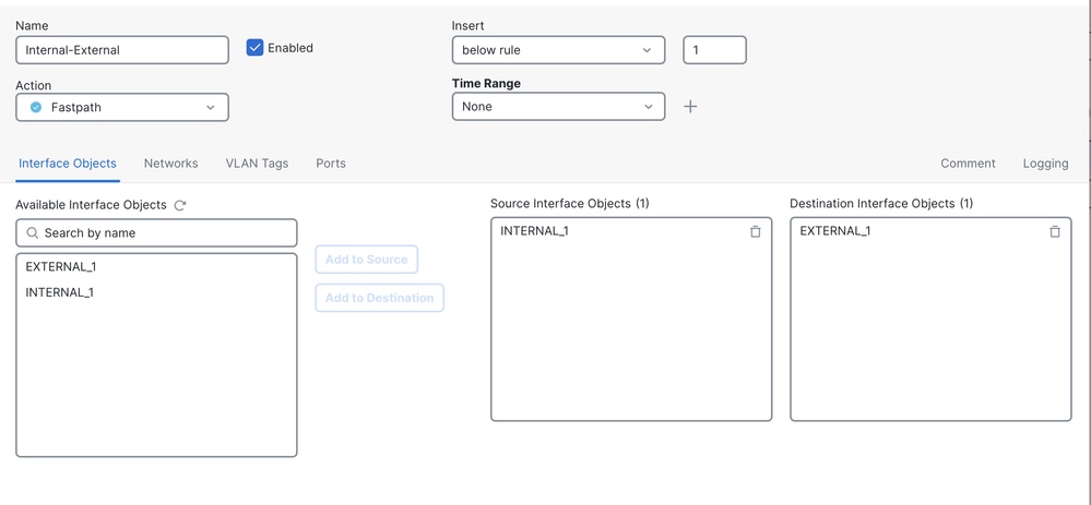
사전 필터 정책:
Fastpath 작업을 사용하여 규칙 internal-external을 사전 필터링합니다.
소스 인터페이스 개체: INTERNAL_1 대상 인터페이스 개체: 외부_1.
액세스 제어 정책은 allow all-any로 구성됩니다.
관찰된 동작
시나리오 1
ISR4451-2(라우터)로 향하는 VM-PC에서 생성된 ICMP 트래픽:
ICMP 트래픽은 다음 경로를 사용합니다.
VM-PC ------ L3Switch ------- FPR4125 ------- ASA 5508 ------FPR4125 ------ L3 Switch ---- ISR 라우터
ICMP 트래픽은 FPR 4125에서 동일한 인라인 쌍(INSIDE-2 >>EXTERNAL2)을 통해 인입 및 이그레스되므로 FMC 연결 이벤트에는 하나의 연결 이벤트만 표시됩니다.
Policy-Based Routing (PBR) is configured on the switch interfaces connected to the firewall and router. This was necessary because, when a PC tries to communicate with the ISR router's IP address, it does not send traffic to the FTD or ASA by default since the router is directly connected to the switch. According to the switch's routing table, the PC and router communicate directly with each other.
FTD를 통한 트래픽 검사 요구 사항을 충족하기 위해 FTD를 통해 트래픽(요청 및 응답 모두)을 리디렉션하도록 PBR을 구성해야 했습니다. 따라서 PC와 라우터에 연결된 스위치 인터페이스에 PBR을 구성했습니다.
시나리오 2
ISR4451-2(라우터)로 향하는 VM-PC에서 생성된 ICMP 트래픽:
ICMP 트래픽은 다음 경로를 사용합니다.
VM-PC ------ L3Switch ------- FPR4125 ------- ASA 5508 ------FPR4125 ------ L3 Switch ---- ISR 라우터
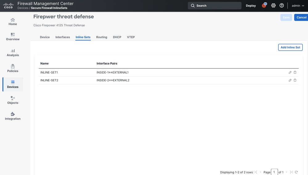
위의 그림에 나와 있는 것처럼 인라인 쌍 컨피그레이션을 두 개의 서로 다른 인라인 세트로 분리할 때 이 트래픽은 INSIDE-1을 통해 FTD를 우회하고 EXTERNAL2를 통해 유입됩니다.
따라서 두 인라인 집합이 사용됩니다.
FMC에서 연결 이벤트를 관찰할 때 2개의 연결 이벤트가 표시되는데, 하나는 발신 트래픽에 대한 것이고, 다른 하나는 수신 트래픽에 대한 것입니다.
이러한 동작의 원인은 FTD의 트래픽이 동일한 트래픽에 대해 서로 다른 두 인라인 쌍을 사용할 때마다 FMC에서 항상 두 개의 연결 이벤트가 표시되기 때문입니다.
 피드백
피드백