독립형 Catalyst 6500 스위치를 Catalyst 6500 VSS로 마이그레이션
목차
소개
이 문서에서는 독립형 Cisco Catalyst 6500 Series 스위치를 Cisco Catalyst 6500 Virtual Switching System으로 마이그레이션하는 절차에 대한 정보를 제공합니다.
참고: 이 문서에서는 마이그레이션에 필요한 일반적인 단계를 제공합니다. 정확한 단계는 현재 스위치 컨피그레이션에 따라 다르며 앞서 언급한 절차와는 약간 다를 수 있습니다.
사전 요구 사항
요구 사항
다음 주제에 대한 지식을 보유하고 있으면 유용합니다.
-
VSS(Virtual Switching Systems) 개념에 대한 지식 자세한 내용은 가상 스위칭 시스템 이해를 참조하십시오.
사용되는 구성 요소
이 문서의 정보는 Cisco IOS® Software Release 12.2(33)SXH1 이상을 실행하는 Supervisor VS-S720-10G-3C/XL이 포함된 Cisco Catalyst 6500 Series 스위치를 기반으로 합니다.
이 문서의 정보는 특정 랩 환경의 디바이스를 토대로 작성되었습니다. 현재 네트워크가 작동 중인 경우, 모든 명령어의 잠재적인 영향을 미리 숙지하시기 바랍니다.
표기 규칙
문서 규칙에 대한 자세한 내용은 Cisco 기술 팁 표기 규칙을 참고하십시오.
배경 정보
VSS(Virtual Switching System)는 Cisco Catalyst 6500 시리즈 스위치의 새롭고 혁신적인 기능으로, 두 개의 물리적 섀시를 하나의 논리적 엔티티로 효과적으로 클러스터링할 수 있습니다. 이러한 기술을 통해 고가용성, 확장성/성능, 관리 및 유지 보수를 포함한 엔터프라이즈 캠퍼스 및 데이터 센터 구축 영역의 모든 영역에서 새로운 개선 사항이 가능합니다.
VSS를 현재 구현하면 두 개의 물리적 Cisco Catalyst 6500 시리즈 스위치를 논리적으로 관리되는 단일 엔티티로 통합할 수 있습니다. 이 그림은 VSS가 활성화되면 두 개의 6509 섀시를 단일 18슬롯 섀시로 관리할 수 있는 이 개념을 그래픽으로 나타낸 것입니다.

마이그레이션 프로세스
하드웨어 및 소프트웨어 지원
VSS는 Cisco Catalyst 6500 시리즈 스위치에서만 사용할 수 있는 소프트웨어 기능입니다. 이 기능을 활성화하고 구성하려면 다음 작업이 필요합니다.
| 하드웨어 | VS-S720-10G-3C/XL |
| 소프트웨어 | Cisco IOS Software 릴리스 12.2(33)SXH1 이상 |
| 모델 번호 | 설명 |
| WS-C6503-E | E 시리즈 3 슬롯 섀시 |
| WS-C6504-E | E 시리즈 4슬롯 섀시 |
| WS-C6506 | 6슬롯 섀시 |
| WS-C6506-E | E 시리즈 6슬롯 섀시 |
| WS-C6509 | 9슬롯 섀시 |
| WS-C6509-E | E 시리즈 9 슬롯 섀시 |
| WS-C6509-NEB-A | 9슬롯 NEBS(Vertical Network Equipment Building Standard) 섀시 |
| WS-C6509-V-E | E 시리즈 9 슬롯 수직 섀시 |
| WS-C6513 | 13슬롯 섀시 |
이 표에는 Cisco Virtual Switching System의 초기 릴리스에서 지원되는 섀시의 전체 목록이 나와 있습니다. 자세한 내용은 Cisco Catalyst 6500 Series VSS(Virtual Switching System) 1440을 참조하십시오.
마이그레이션 경로
이 표에는 VSS에 대한 가능한 마이그레이션 경로 중 일부가 나열되어 있습니다. 이 목록은 단지 암시적일 뿐 포괄적이지는 않다.
| 초기 설정 | 업그레이드 필요 | 최종 설정 |
|---|---|---|
| WS-SUP720-3B 수퍼바이저가 포함된 Cisco Catalyst 6500 Series 스위치 2개. |
하드웨어 업그레이드 - 수퍼바이저 VS-S720-10G-3C/XL 소프트웨어 업그레이드 - Cisco IOS 12.2(33)SXH1 이상 | VSS |
| VS-S720-10G-3C/XL 수퍼바이저가 포함된 Cisco Catalyst 6500 Series 스위치 2개. |
소프트웨어 업그레이드 - Cisco IOS 12.2(33)SXH1 이상 | VSS |
마이그레이션 개요
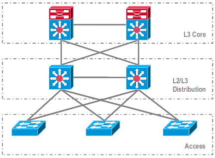
독립형 환경의 공통 구성

레이어 3(L3) 코어와 L2/L3 디스트리뷰션 간에 실행되는 기능 또는 프로토콜:
-
IP 라우팅 프로토콜
-
IP 라우팅의 L3 포트 채널 또는 EqualCost MultiPath 기능
L2/L3 디스트리뷰션 및 액세스 레이어 간에 실행되는 기능 또는 프로토콜:
-
스패닝 트리 프로토콜
-
FHRP(First Hop Routing Protocols)
-
정책: QoS, ACL
-
L2 트렁크, VLAN, 포트 채널
VSS로 마이그레이션
이 프로세스는 다중 단계 프로세스이며 각 단계에 대해 이 섹션에서 설명합니다.

코어 및 디스트리뷰션 레이어 간 마이그레이션 단계:
-
MEC(MultiChassis EtherChannel) 구성
-
IP 라우팅 컨피그레이션 수정 및 명령 제거(더 이상 필요 없음)
디스트리뷰션 레이어 및 액세스 레이어 간 마이그레이션 단계:
-
MEC 구성
-
스패닝 트리 프로토콜 활성화 유지
-
FHRP 명령 수정
-
QoS 및 ACL 정책을 MEC로 이동(필요한 경우)
-
L2 트렁크 컨피그레이션을 MEC로 이동
단계별 마이그레이션 프로세스
다음 단계를 완료하십시오.
-
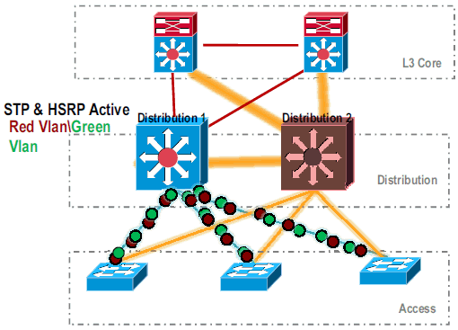
초기 독립형 설정에서 트래픽은 일반적으로 VLAN 로드 공유 및 HSRP 컨피그레이션을 사용하여 디스트리뷰션 스위치 간에 로드 밸런싱됩니다.

-
HSRP 및 STP 컨피그레이션을 수정하여 Distribution-1이 모든 플로우에 대해 활성화되고 인접 디바이스에서 이 변경 사항을 탐지하고 모든 트래픽을 Distribution-1로 전송합니다.

-
Distribution-2의 물리적 인터페이스를 종료하여 네트워크에서 격리합니다.

.
네트워크에서 Distribution-2가 완전히 제거되면 운영 트래픽을 중단하지 않고 VSS 모드로 변환할 수 있습니다.
-
이전에 설치되지 않은 경우 새 수퍼바이저(VS-SUP720-10G)를 설치하고 상태를 확인합니다.
Distribution-2#show module
Mod Ports Card Type                              Model              Serial No.
--- ----- -------------------------------------- ------------------ -----------
  5    5  Supervisor Engine 720 10GE (Active)    VS-S720-10G        SAD104707BB
  9   48  CEF 720 48 port 10/100/1000mb Ethernet WS-X6748-GE-TX     SAL1020NGY3
-
VSS 호환 Cisco IOS 소프트웨어를 sup-bootdisk에 복사합니다.
Distribution-2#copy ftp: sup-bootdisk:
Address or name of remote host []? 172.16.85.150
Source filename []? s72033-ipservices_wan_vz.122-33.SXH1.bin
Destination filename [s72033-ipservices_wan_vz.122-33.SXH1.bin]?
Accessing ftp://172.16.85.150/s72033-ipservices_wan_vz.122-33.SXH1.bin...
-
sup-bootdisk에 복사된 Cisco IOS 소프트웨어를 로드하려면 bootvar을 업데이트합니다.
Distribution-2(config)#boot system flash sup-bootdisk:s72033-ipservices_wan_vz.122-33.SXH1.bin -
VSS 모드에서 Distribution-2 스위치를 실행하려면 VSL(Virtual Switch Link)이 필요합니다. Distribution-1과 Distribution-2 사이의 현재 포트 채널 링크를 사용하여 VSL을 구성할 수 있습니다.

-
가상 스위치 특성을 구성합니다.
-
가상 스위치 도메인 번호(네트워크 내에서 고유)
-
가상 스위치 번호(도메인 내에서 고유)
-
VSL(Virtual Switch Link)
Distribution-2(config)#hostname VSS

VSS(config)#switch virtual domain 100

VSS(config-vs-domain)#switch 1


!--- After conversion Distribution-2 will be noted !--- as Switch 1 in VSS mode.

VSS(config-vs-domain)# exit
VSS(config)#interface port-channel 1
VSS(config-if)#switch virtual link 1

VSS(config-if)#interface TenG 5/4
VSS(config-if)#channel-group 1 mode on
VSS(config-if)#interface TenG 5/5
VSS(config-if)#channel-group 1 mode on
VSS(config-if)# ^Z
VSS#
-
-
Distribution-2 스위치를 VSS 모드로 변환합니다.
참고: 스위치의 콘솔을 통해 이 명령을 실행합니다.
VSS#switch convert mode virtual

This command will convert all interface
names to naming convention "interface-type
switch-number/slot/port",
save the running config to startup-config and
reload the switch.
Do you want to proceed? [yes/no]: yes
Converting interface names
Building configuration...


!--- At this point the switch will reboot


!--- snippet of the console output

System detected Virtual Switch configuration...
 Interface TenGigabitEthernet 1/5/4 is member of
PortChannel 1
 Interface TenGigabitEthernet 1/5/5 is member of
PortChannel 1

!--- snippet of the console output

00:00:23: %PFREDUN-6-ACTIVE: Initializing as ACTIVE
processor for this switch

!--- snippet of the console output

00:00:28: %VSL_BRINGUP-6-MODULE_UP: VSL module in slot 5
switch 1 brought up
Initializing as Virtual Switch Active
-
Distribution-2 스위치를 VSS 모드로 변환하는지 확인합니다.
VSS#show switch virtual role Switch Switch Status Preempt Priority Role Session ID Number Oper(Conf) Oper(Conf) Local Remote ------------------------------------------------------------------- LOCAL 1 UP FALSE(N) 110(110) ACTIVE 0 0 In dual-active recovery mode: NoDistribution-2 스위치가 성공적으로 변환되어 VSS 모드에서 작동 중입니다. Distribution-1 스위치를 변환한 후 사전 구성 단계를 수행할 수도 있습니다. 그러나 사전 컨피그레이션은 마이그레이션 중에 패킷 손실량을 줄이는 데 도움이 됩니다.

-
VSS 스위치 1을 사전 구성하려면 다음 단계를 완료합니다.
-
Switch-1의 로컬 인터페이스를 사용하여 MEC를 구성합니다. Switch-2(현재 Distribution-1)의 인터페이스는 VSS 모드로 변환한 후 MEC에 추가할 수 있습니다.
-
MEC를 구성합니다.
-
인터페이스 컨피그레이션을 MEC로 이동합니다.
-
QoS 및 ACL 정책을 MEC로 이동합니다.
구성 변경interface TenGigabitEthernet1/2/1 ip address 192.168.4.2 255.255.255.0 interface GigabitEthernet1/1/2 switchport switchport trunk encapsulation dot1q switchport trunk allowed vlan 10,20
포트 채널을 수용하도록 인접 디바이스 구성!--- MEC to Core layer VSS(config)# int ten 1/2/1 VSS(config-if)# no ip address VSS(config-if)# interface po20 VSS(config-if)# ip address 192.168.4.2 255.255.255.0 VSS(config-if)# no shut VSS(config-if)# interface ten1/2/1 VSS(config-if)# channel-group 20 mode desirable !--- MEC to Access layer VSS(config-if)# interface po10 VSS(config-if)# switchport VSS(config-if)# switchport trunk encapsulation dot1q VSS(config-if)# switchport trunk allowed vlan 10,20 VSS(config-if)# no shut VSS(config-if)# interface gig1/1/2 VSS(config-if)# switchport VSS(config-if)# channel-group 10 mode desirable
VSS Switch-1과 인접 디바이스 간의 연결이 현재 중단됩니다. 따라서 포트 채널은 Distribution-1을 통한 트래픽 흐름을 방해하지 않고 구성됩니다.
!--- In Core layer devices

Core(config)# int gig 1/1
Core(config-if)# no ip address
Core(config-if)# int po20
Core(config-if)# ip address 192.168.4.1 255.255.255.0
Core(config-if)# no shut
Core(config-if)# int gig 1/1
Core(config-if)# channel-group 20 mode desirable
!--- In Access layer devices

Access(config)# int po10
Access(config-if)# switchport
Access(config-if)# switchport trunk encapsulation dot1q
Access(config-if)# switchport trunk
Access(config-if)# no shut
Access(config-if)# int gig 1/1
Access(config-if)# channel-group 10 mode desirable
-
-
VSS에서 액티브 섀시와 스탠바이 섀시 모두 활성 섀시 번드 인 MAC 주소 및 VLAN IP 주소를 사용합니다. HSRP는 더 이상 필요하지 않습니다.
-
HSRP 가상 IP 주소를 VLAN 인터페이스로 이동합니다.
-
VLAN 인터페이스에서 HSRP 컨피그레이션을 제거합니다.
구성 변경interface Vlan10 ip address 10.1.1.2 255.255.255.0 standby 10 ip 10.1.1.1 standby 10 priority 110 ! interface Vlan20 ip address 20.1.1.2 255.255.255.0 standby 20 ip 20.1.1.1 standby 20 priority 110 !
VSS(config)# interface Vlan10
VSS(config-if)# no standby 10 ip 10.1.1.1
VSS(config-if)# no standby 10 priority 110
VSS(config-if)# ip address 10.1.1.1 255.255.255.0
VSS(config-if)# interface Vlan20
VSS(config-if)# no standby 20 ip 20.1.1.1
VSS(config-if)# no standby 20 priority 110
VSS(config-if)# ip address 20.1.1.1 255.255.255.0
참고: 최종 디바이스는 여전히 ARP 항목을 초기 HSRP MAC 주소로 가리키게 됩니다. 이러한 항목이 시간 초과되거나 다른 ARP가 캐시 업데이트를 위해 전송될 때까지 일부 연결 손실이 발생합니다.
-
-
사용된 IP 라우팅 프로토콜에 대해 NSF-SSO 기능을 활성화합니다. VSS는 라우팅 컨피그레이션을 간소화하므로 일부 네트워크 명령문이 더 이상 필요하지 않습니다. 따라서 제거할 수 있습니다.
VSS 스위치-1
코어VSS#show running-config | begin ospf router ospf 1 log-adjacency-changes network 10.1.1.0 0.0.0.255 area 0 network 20.1.1.0 0.0.0.255 area 0 network 192.168.4.0 0.0.0.255 area 0 network 192.168.5.0 0.0.0.255 area 0 !--- rest of output elided !--- Previous L3 interfaces are merged as MEC, hence some routing statements are no longer required. VSS(config)# router ospf 1 VSS(config-router)# nsf VSS(config-router)# no network 192.168.5.0 0.0.0.255 area 0
Core#show running-config | begin ospf
router ospf 1
 log-adjacency-changes
 network 192.168.4.0 0.0.0.255 area 0
 network 192.168.5.0 0.0.0.255 area 0

!--- rest of output elided


!--- Previous L3 interfaces are merged as MEC, hence some routing statements are no longer required.


Core(config)# router ospf 1
Core(config-router)# nsf
Core(config-router)# no network 192.168.5.0 0.0.0.255 area 0
-
VSS Switch-1이 모든 VLAN의 루트가 되도록 STP 컨피그레이션을 수정합니다.
-
-
VSS Switch-1 구성 및 연결을 확인합니다.
-
VSS Switch-1 인터페이스를 활성화합니다.
-
액세스 레이어 디바이스에 대한 L2 연결을 확인합니다.
-
코어 레이어 디바이스에 대한 L3 연결을 확인합니다.

-
-
VSS Switch-1 연결이 확인되면 Distribution-1 인터페이스를 종료하여 트래픽을 VSS로 전환합니다.

-
Distribution-1 스위치에서 변환 단계를 반복하여 기본 VSS 대기 모드로 전환합니다.
Distribution-1(config)#hostname VSS

VSS(config)#switch virtual domain 100

VSS(config-vs-domain)#switch 2


!--- After conversion Distribution-1 will be noted !--- as Switch 2 in VSS mode.

VSS(config-vs-domain)# exit
VSS(config)#interface port-channel 2
VSS(config-if)#switch virtual link 2

VSS(config-if)#interface TenG 5/4
VSS(config-if)#channel-group 2 mode on
VSS(config-if)#interface TenG 5/5
VSS(config-if)#channel-group 2 mode on
VSS(config-if)# ^Z
VSS#

VSS#switch convert mode virtual

This command will convert all interface
names to naming convention "interface-type
switch-number/slot/port",
save the running config to startup-config and
reload the switch.
Do you want to proceed? [yes/no]: yes
Converting interface names
Building configuration...


!--- At this point the switch will reboot


!--- snippet of the console output

System detected Virtual Switch configuration...
 Interface TenGigabitEthernet 2/5/4 is member of
PortChannel 2
 Interface TenGigabitEthernet 2/5/5 is member of
PortChannel 2

!--- snippet of the console output

00:00:23: %PFREDUN-6-ACTIVE: Initializing as ACTIVE
processor for this switch

!--- snippet of the console output

00:00:28: %VSL_BRINGUP-6-MODULE_UP: VSL module in slot 5
switch 2 brought up
Initializing as Virtual Switch Standby
-
VSS 대기 스위치가 부팅되면 VSS 활성 컨피그레이션이 VSS 대기 상태로 자동 동기화됩니다. 부팅 시 VSS 대기(Switch-2) 인터페이스가 종료 상태입니다.

-
가상 스위치 구성을 완료합니다.
참고: 이 마지막 중요한 단계는 최초 변환에만 적용됩니다. 스위치가 이미 변환되었거나 부분적으로 변환된 경우 이 명령을 사용할 수 없습니다. 스위치가 변환되거나 부분적으로 변환되면 오류 메시지가 생성됩니다.
11:27:30: %PM-SP-4-ERR_DISABLE: channel-misconfig error detected
on Po110, putting Gi9/2 in err-disable state
활성 가상 스위치에서 스탠바이 가상 스위치 컨피그레이션을 자동으로 구성하려면 다음 명령을 실행할 수 있습니다.
VSS#switch accept mode virtual

This command will bring in all VSL configurations from the standby
switch and populate it into the running configuration.
In addition the startup configurations will be updated with the
new merged configurations.
Do you want proceed? [yes/no]: yes
Merging the standby VSL configuration. . .
Building configuration...
참고: switch accept mode virtual 명령은 컨피그레이션이 자동으로 병합되므로 Cisco IOS Software Release 12.2 SXI에서 더 이상 필요하지 않습니다.
-
MEC에 Switch-2 인터페이스를 추가합니다.
- VSS
!--- To Core layer

VSS(config)# interface range tengig 1/2/1, tengig2/2/1
VSS(config-if-range)# channel-group 20 mode desirable
VSS(config-if-range)# no shut


!--- To Access layer

VSS(config)# interface range gig 1/1/2, gig 2/1/2
VSS(config-if-range)# switchport
VSS(config-if-range)# channel-group 10 mode desirable
VSS(config-if-range)# no shut
- VSS 인접 디바이스 - 코어
Core(config)# interface range gig 1/1, gig 1/2
Core(config-if-range)# channel-group 20 mode desirable
Core(config-if-range)# no shut
- VSS 인접 디바이스 - 액세스
Access(config)# interface range gig 1/1, gig 1/2
Access(config-if-range)# channel-group 10 mode desirable
Access(config-if-range)# no shut
VSS로의 마이그레이션이 완료되었습니다. 이 시점에서 두 VSS 스위치 모두 실행 중이며 모든 업링크 인터페이스에서 트래픽이 로드 밸런싱됩니다.

- VSS
관련 정보
개정 이력
| 개정 | 게시 날짜 | 의견 |
|---|---|---|
1.0 |
01-Dec-2013 |
최초 릴리스 |


 피드백
피드백