Configurar o cluster FTD no FP9300 (intra-chassi)
Opções de download
Linguagem imparcial
O conjunto de documentação deste produto faz o possível para usar uma linguagem imparcial. Para os fins deste conjunto de documentação, a imparcialidade é definida como uma linguagem que não implica em discriminação baseada em idade, deficiência, gênero, identidade racial, identidade étnica, orientação sexual, status socioeconômico e interseccionalidade. Pode haver exceções na documentação devido à linguagem codificada nas interfaces de usuário do software do produto, linguagem usada com base na documentação de RFP ou linguagem usada por um produto de terceiros referenciado. Saiba mais sobre como a Cisco está usando a linguagem inclusiva.
Sobre esta tradução
A Cisco traduziu este documento com a ajuda de tecnologias de tradução automática e humana para oferecer conteúdo de suporte aos seus usuários no seu próprio idioma, independentemente da localização. Observe que mesmo a melhor tradução automática não será tão precisa quanto as realizadas por um tradutor profissional. A Cisco Systems, Inc. não se responsabiliza pela precisão destas traduções e recomenda que o documento original em inglês (link fornecido) seja sempre consultado.
Contents
Introduction
Este documento descreve como configurar e verificar o recurso de cluster no dispositivo FPR9300.
Caution: As informações fornecidas neste documento abrangem a instalação/configuração inicial do cluster. Este documento não se aplica a uma substituição de unidade (procedimento de autorização de devolução de material - RMA)
Prerequisites
Requirements
Não existem requisitos específicos para este documento.
Componentes Utilizados
As informações neste documento são baseadas nestas versões de software e hardware:
- Dispositivo de segurança Cisco Firepower 9300 executando 1.1(4.95)
- Firepower Threat Defense (FTD) executando 6.0.1 (build 1213)
- FireSIGHT Management Center (FMC) executando 6.0.1.1 (build 1023)
Hora de conclusão do laboratório: 1 hora.
The information in this document was created from the devices in a specific lab environment. All of the devices used in this document started with a cleared (default) configuration. Se a rede estiver ativa, certifique-se de que você entenda o impacto potencial de qualquer comando.
Informações de Apoio
- No dispositivo FPR9300 com FTD, você pode configurar o Clustering intra-chassi em todas as versões suportadas.
- O agrupamento entre chassis foi apresentado na seção 6.2.
- O canal de porta 48 é criado como um link de controle de cluster. Para o agrupamento entre chassis, este link utiliza o painel traseiro Firepower 9300 para comunicações em cluster.
- Interfaces de dados individuais não são suportadas, com exceção de uma interface de gerenciamento.
- A interface de gerenciamento é atribuída a todas as unidades no cluster.
Configurar
Diagrama de Rede

Tarefa 1. Criar interfaces necessárias para o cluster FTD
Requisito de tarefa:
Crie um cluster, uma interface de gerenciamento e uma interface de dados do canal de porta.
Solução:
Etapa 1. Crie uma interface de Dados do canal da porta.
Para criar uma nova interface, você precisa fazer login no FPR9300 Chassis Manager e navegar até a guia Interfaces.
Selecione Add Port Channel e crie uma nova Port Channel Interface com estes parâmetros:
| ID do canal da porta |
5 |
| Tipo |
Dados |
| Enable |
Yes |
| ID do membro |
Ethernet1/3, Ethernet 1/4 |
Selecione OK para salvar a configuração como mostrado na imagem.

Etapa 2. Crie uma interface de gerenciamento.
Na guia Interfaces, escolha a interface, clique em Edit e configure a interface Management Type.
Clique em OK para salvar a configuração como mostrado na imagem.

Etapa 3. Crie uma Interface de Link de Controle de Cluster.
Clique no botão Add Port Channel e crie uma nova Port Channel Interface com esses parâmetros e conforme mostrado na imagem.
| ID do canal da porta |
48 |
| Tipo |
Cluster |
| Enable |
Yes |
| ID do membro |
- |

Tarefa 2. Criar cluster FTD
Requisito de tarefa:
Crie uma unidade de cluster FTD.
Solução:
Etapa 1. Navegue até Dispositivos lógicos e clique no botão Adicionar dispositivo.
Crie o cluster FTD da seguinte maneira:
| Nome de dispositivo |
FTD_cluster |
| Modelo |
Defesa contra ameaças do Cisco Firepower |
| Versão da imagem |
6.0.1.1213 |
| Modo do dispositivo |
Cluster |
Para adicionar o dispositivo, clique em OK conforme mostrado na imagem.

Etapa 2. Configure e implante o cluster FTD.
Depois de criar um dispositivo FTD, você é redirecionado para a janela Provisioning- device_name.
Clique no ícone do dispositivo para iniciar a configuração conforme mostrado na imagem.
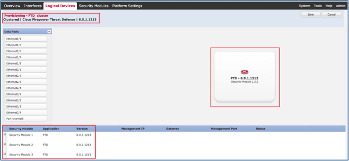
Configure a guia Informações do Cluster FTD com essas configurações e conforme mostrado na imagem.
| Chave do cluster |
cisco |
| Nome do grupo de cluster |
FTD_cluster |
| Interface de gerenciamento |
Ethernet1/1 |

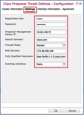
Configure a guia Configurações do FTD com essas configurações e conforme mostrado na imagem.
| Chave de registro |
cisco |
| Senha |
Admin123 |
| IP do Firepower Management Center |
10.62.148.73 |
| Domínios de pesquisa |
cisco.com |
| Modo de firewall |
Roteado |
| Servidores DNS |
173.38.200.100 |
| Nome de host totalmente qualificado |
ksec-fpr9k-1-1-3.cisco.com |
| Interface de evento |
Nenhum |
Configure a guia Interface Information FTD com essas configurações e conforme mostrado na imagem.
| Tipo de endereço |
Somente IPv4 |
| Módulo de segurança 1 |
|
| IP de gerenciamento |
10.62.148.67 |
| Máscara de rede |
255.255.255.128 |
| Gateway |
10.62.148.1 |
| Módulo de segurança 2 |
|
| IP de gerenciamento |
10.62.148.68 |
| Máscara de rede |
255.255.255.128 |
| Gateway |
10.62.148.1 |
| Módulo de segurança 3 |
|
| IP de gerenciamento |
10.62.148.69 |
| Máscara de rede |
255.255.255.128 |
| Gateway |
10.62.148.1 |

Aceite o Contrato na guia Contrato e clique em OK conforme mostrado na imagem.

Etapa 3. Atribuir interfaces de dados ao FTD.
Expanda a área de Portas de Dados e clique em cada interface que deseja atribuir ao FTD. Após a conclusão, selecione Salvar para criar um cluster FTD como mostrado na imagem.
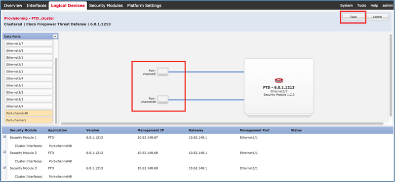
Aguarde alguns minutos para que o cluster seja implantado, após os quais a eleição da unidade mestre ocorrerá.
Verificação:
- Na GUI do FPR9300, como mostrado na imagem.

- Da CLI FPR9300
FPR9K-1-A#
FPR9K-1-A# scope ssa
FPR9K-1-A /ssa # show app-instance
Application Name     Slot ID    Admin State     Operational State    Running Version Startup Version Cluster Oper State
-------------------- ---------- --------------- -------------------- --------------- --------------- ------------------
ftd                  1          Enabled         Online               6.0.1.1213      6.0.1.1213      In Cluster
ftd                  2          Enabled         Online               6.0.1.1213      6.0.1.1213      In Cluster
ftd                  3          Enabled         Online               6.0.1.1213      6.0.1.1213      In Cluster
- Da CLI do LINA (ASA)
firepower# show cluster info
Cluster FTD_cluster: On
    Interface mode: spanned
    This is "unit-1-1" in state MASTER
        ID        : 0
        Version   : 9.6(1)
        Serial No.: FLM19216KK6
        CCL IP    : 127.2.1.1
        CCL MAC   : 0015.c500.016f
        Last join : 21:51:03 CEST Aug 8 2016
        Last leave: N/A
Other members in the cluster:
    Unit "unit-1-3" in state SLAVE
        ID        : 1
        Version   : 9.6(1)
        Serial No.: FLM19206H7T
        CCL IP    : 127.2.1.3
        CCL MAC   : 0015.c500.018f
        Last join : 21:51:05 CEST Aug 8 2016
        Last leave: N/A
    Unit "unit-1-2" in state SLAVE
        ID        : 2
        Version   : 9.6(1)
        Serial No.: FLM19206H71
        CCL IP    : 127.2.1.2
        CCL MAC   : 0015.c500.019f
        Last join : 21:51:30 CEST Aug 8 2016
        Last leave: N/A
firepower# cluster exec show cluster interface-mode
cluster interface-mode spanned


unit-1-3:*************************************************************
cluster interface-mode spanned


unit-1-2:*************************************************************
cluster interface-mode spanned
firepower#
firepower# cluster exec show cluster history
==========================================================================
From State           To State             Reason
==========================================================================
21:49:25 CEST Aug 8 2016
DISABLED             DISABLED             Disabled at startup

21:50:18 CEST Aug 8 2016
DISABLED             ELECTION             Enabled from CLI

21:51:03 CEST Aug 8 2016
ELECTION             MASTER_POST_CONFIG   Enabled from CLI

21:51:03 CEST Aug 8 2016
MASTER_POST_CONFIG   MASTER               Master post config done and waiting for ntfy

==========================================================================


unit-1-3:*************************************************************
==========================================================================
From State           To State             Reason
==========================================================================
21:49:44 CEST Aug 8 2016
DISABLED             DISABLED             Disabled at startup

21:50:37 CEST Aug 8 2016
DISABLED             ELECTION             Enabled from CLI

21:50:37 CEST Aug 8 2016
ELECTION             ONCALL               Received cluster control message

21:50:41 CEST Aug 8 2016
ONCALL               ELECTION            Received cluster control message

21:50:41 CEST Aug 8 2016
ELECTION             ONCALL               Received cluster control message

21:50:46 CEST Aug 8 2016
ONCALL               ELECTION             Received cluster control message

21:50:46 CEST Aug 8 2016
ELECTION             ONCALL               Received cluster control message

21:50:51 CEST Aug 8 2016
ONCALL               ELECTION             Received cluster control message

21:50:51 CEST Aug 8 2016
ELECTION             ONCALL                Received cluster control message

21:50:56 CEST Aug 8 2016
ONCALL               ELECTION             Received cluster control message

21:50:56 CEST Aug 8 2016
ELECTION             ONCALL               Received cluster control message

21:51:01 CEST Aug 8 2016
ONCALL               ELECTION             Received cluster control message

21:51:01 CEST Aug 8 2016
ELECTION             ONCALL               Received cluster control message

21:51:04 CEST Aug 8 2016
ONCALL               SLAVE_COLD          Received cluster control message

21:51:04 CEST Aug 8 2016
SLAVE_COLD           SLAVE_APP_SYNC       Client progression done

21:51:05 CEST Aug 8 2016
SLAVE_APP_SYNC       SLAVE_CONFIG         Slave application configuration sync done

21:51:17 CEST Aug 8 2016
SLAVE_CONFIG         SLAVE_BULK_SYNC       Configuration replication finished

21:51:29 CEST Aug 8 2016
SLAVE_BULK_SYNC       SLAVE                 Configuration replication finished

==========================================================================


unit-1-2:*************************************************************
==========================================================================
From State           To State             Reason
==========================================================================
21:49:24 CEST Aug 8 2016
DISABLED             DISABLED             Disabled at startup

21:50:16 CEST Aug 8 2016
DISABLED             ELECTION             Enabled from CLI

21:50:17 CEST Aug 8 2016
ELECTION              ONCALL               Received cluster control message

21:50:21 CEST Aug 8 2016
ONCALL               ELECTION             Received cluster control message

21:50:21 CEST Aug 8 2016
ELECTION             ONCALL               Received cluster control message

21:50:26 CEST Aug 8 2016
ONCALL               ELECTION             Received cluster control message

21:50:26 CEST Aug 8 2016
ELECTION             ONCALL               Received cluster control message

21:50:31 CEST Aug 8 2016
ONCALL               ELECTION             Received cluster control message

21:50:31 CEST Aug 8 2016
ELECTION             ONCALL               Received cluster control message

21:50:36 CEST Aug 8 2016
ONCALL               ELECTION             Received cluster control message

21:50:36 CEST Aug 8 2016
ELECTION             ONCALL               Received cluster control message

21:50:41 CEST Aug 8 2016
ONCALL               ELECTION             Received cluster control message

21:50:41 CEST Aug 8 2016
ELECTION             ONCALL               Received cluster control message

21:50:46 CEST Aug 8 2016
ONCALL               ELECTION             Received cluster control message

21:50:46 CEST Aug 8 2016
ELECTION             ONCALL                Received cluster control message

21:50:51 CEST Aug 8 2016
ONCALL               ELECTION             Received cluster control message

21:50:51 CEST Aug 8 2016
ELECTION             ONCALL               Received cluster control message

21:50:56 CEST Aug 8 2016
ONCALL               ELECTION             Received cluster control message

21:50:56 CEST Aug 8 2016
ELECTION             ONCALL               Received cluster control message

21:51:01 CEST Aug 8 2016
ONCALL               ELECTION             Received cluster control message

21:51:01 CEST Aug 8 2016
ELECTION             ONCALL               Received cluster control message

21:51:06 CEST Aug 8 2016
ONCALL               ELECTION             Received cluster control message

21:51:06 CEST Aug 8 2016
ELECTION             ONCALL               Received cluster control message

21:51:12 CEST Aug 8 2016
ONCALL               ELECTION             Received cluster control message

21:51:12 CEST Aug 8 2016
ELECTION              ONCALL               Received cluster control message

21:51:17 CEST Aug 8 2016
ONCALL               ELECTION             Received cluster control message

21:51:17 CEST Aug 8 2016
ELECTION             ONCALL               Received cluster control message

21:51:22 CEST Aug 8 2016
ONCALL               ELECTION             Received cluster control message

21:51:22 CEST Aug 8 2016
ELECTION             ONCALL               Received cluster control message

21:51:27 CEST Aug 8 2016
ONCALL               ELECTION             Received cluster control message

21:51:27 CEST Aug 8 2016
ELECTION             ONCALL               Received cluster control message

21:51:30 CEST Aug 8 2016
ONCALL               SLAVE_COLD          Received cluster control message

21:51:30 CEST Aug 8 2016
SLAVE_COLD           SLAVE_APP_SYNC       Client progression done

21:51:31 CEST Aug 8 2016
SLAVE_APP_SYNC       SLAVE_CONFIG         Slave application configuration sync done

21:51:43 CEST Aug 8 2016
SLAVE_CONFIG         SLAVE_BULK_SYNC       Configuration replication finished

21:51:55 CEST Aug 8 2016
SLAVE_BULK_SYNC       SLAVE                 Configuration replication finished

==========================================================================
firepower#
Tarefa 3. Registrar cluster FTD no FMC
Requisito de tarefa:
Adicione os dispositivos lógicos ao FMC e agrupe-os em um cluster.
Solução:
Etapa 1. Adicione dispositivos lógicos ao FMC. A partir da versão 6.3 do FMC, você deve registrar apenas um dispositivo FTD (recomendado para ser o mestre). O resto dos DTFs são descobertos automaticamente pelo CVP.
Efetue login no FMC e navegue até a guia Devices > Device Management e clique em Add Device.
Adicione o primeiro dispositivo lógico com as configurações mencionadas na imagem.
Clique em Registrar para iniciar o registro.
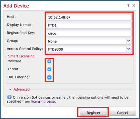
A verificação é como mostrado na imagem.

Tarefa 4. Configurar subinterfaces de canal de porta no FMC
Requisito de tarefa:
Configure subinterfaces para a interface Dados do canal de porta.
Solução:
Etapa 1. Na GUI do FMC, selecione o botão FTD_cluster Edit.
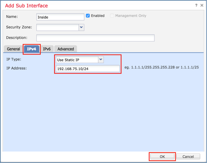
Navegue até a guia Interfaces (Interfaces) e clique em Add Interfaces > Sub Interface (Adicionar interfaces), conforme mostrado na imagem.

Configure a primeira subinterface com esses detalhes. Selecione OK para aplicar as alterações e conforme mostrado nas imagens.
| Nome |
Interna |
| guia Geral |
|
| Interface |
Canal de porta 5 |
| ID da subinterface |
201 |
| ID da VLAN |
201 |
| guia IPv4 |
|
| Tipo de IP |
Usar IP estático |
| IP Address |
192.168.75.10/24 |

Configure a segunda subinterface com esses detalhes.
| Nome |
Externa |
| guia Geral |
|
| Interface |
Canal de porta 5 |
| ID da subinterface |
210 |
| ID da VLAN |
210 |
| guia IPv4 |
|
| Tipo de IP |
Usar IP estático |
| IP Address |
192.168.76.10/24 |
Clique em OK para criar a subinterface. Clique em Salvar e em Implantar alterações no FTD_cluster, como mostrado na imagem.
Verificação:

Tarefa 5. Verificar a conectividade básica
Requisito de tarefa:
Crie uma captura e verifique a conectividade entre duas VMs.
Solução:
Etapa 1. Criar capturas em todas as unidades de cluster.
Navegue até LINA (ASA) CLI da unidade Master e crie capturas para as interfaces interna e externa.
firepower#
firepower# cluster exec capture capi interface inside match icmp any any
unit-1-1(LOCAL):******************************************************


unit-1-3:*************************************************************


unit-1-2:*************************************************************
firepower#
firepower# cluster exec capture capo interface outside match icmp any any
unit-1-1(LOCAL):******************************************************


unit-1-3:*************************************************************


unit-1-2:*************************************************************
firepower#
Verificação:
firepower# cluster exec show capture
unit-1-1(LOCAL):******************************************************
capture capi type raw-data interface Inside [Capturing - 0 bytes]
  match icmp any any
capture capo type raw-data interface Outside [Capturing - 0 bytes]
  match icmp any any


unit-1-3:*************************************************************
capture capi type raw-data interface Inside [Capturing - 0 bytes]
  match icmp any any
capture capo type raw-data interface Outside [Capturing - 0 bytes]
  match icmp any any


unit-1-2:*************************************************************
capture capi type raw-data interface Inside [Capturing - 0 bytes]
  match icmp any any
capture capo type raw-data interface Outside [Capturing - 0 bytes]
  match icmp any any
firepower#
Etapa 2. Execute o teste de ping da VM1 para a VM2.
Faça o teste com 4 pacotes. Verifique a saída da captura após o teste:
firepower# cluster exec show capture
unit-1-1(LOCAL):******************************************************
capture capi type raw-data interface Inside [Capturing - 0 bytes]
  match icmp any any
capture capo type raw-data interface Outside [Capturing - 0 bytes]
  match icmp any any


unit-1-3:*************************************************************
capture capi type raw-data interface Inside [Capturing - 752 bytes]
  match icmp any any
capture capo type raw-data interface Outside [Capturing - 752 bytes]
  match icmp any any


unit-1-2:*************************************************************
capture capi type raw-data interface Inside [Capturing - 0 bytes]
  match icmp any any
capture capo type raw-data interface Outside [Capturing - 0 bytes]
  match icmp any any
firepower#
Execute o comando para verificar a saída da captura na unidade específica:
firepower# cluster exec unit unit-1-3 show capture capi

8 packets captured

   1: 12:58:36.162253       802.1Q vlan#201 P0 192.168.75.100 > 192.168.76.100: icmp: echo request
   2: 12:58:36.162955       802.1Q vlan#201 P0 192.168.76.100 > 192.168.75.100: icmp: echo reply
   3: 12:58:37.173834       802.1Q vlan#201 P0 192.168.75.100 > 192.168.76.100: icmp: echo request
   4: 12:58:37.174368       802.1Q vlan#201 P0 192.168.76.100 > 192.168.75.100: icmp: echo reply
   5: 12:58:38.187642       802.1Q vlan#201 P0 192.168.75.100 > 192.168.76.100: icmp: echo request
   6: 12:58:38.188115       802.1Q vlan#201 P0 192.168.76.100 > 192.168.75.100: icmp: echo reply
   7: 12:58:39.201832       802.1Q vlan#201 P0 192.168.75.100 > 192.168.76.100: icmp: echo request
   8: 12:58:39.202321       802.1Q vlan#201 P0 192.168.76.100 > 192.168.75.100: icmp: echo reply
8 packets shown

firepower# cluster exec unit unit-1-3 show capture capo

8 packets captured

   1: 12:58:36.162543       802.1Q vlan#210 P0 192.168.75.100 > 192.168.76.100: icmp: echo request
   2: 12:58:36.162894       802.1Q vlan#210 P0 192.168.76.100 > 192.168.75.100: icmp: echo reply
   3: 12:58:37.174002       802.1Q vlan#210 P0 192.168.75.100 > 192.168.76.100: icmp: echo request
   4: 12:58:37.174307       802.1Q vlan#210 P0 192.168.76.100 > 192.168.75.100: icmp: echo reply
   5: 12:58:38.187764       802.1Q vlan#210 P0 192.168.75.100 > 192.168.76.100: icmp: echo request
   6: 12:58:38.188085       802.1Q vlan#210 P0 192.168.76.100 > 192.168.75.100: icmp: echo reply
   7: 12:58:39.201954       802.1Q vlan#210 P0 192.168.75.100 > 192.168.76.100: icmp: echo request
   8: 12:58:39.202290       802.1Q vlan#210 P0 192.168.76.100 > 192.168.75.100: icmp: echo reply
8 packets shown
firepower#
Após concluir esta tarefa, exclua as capturas com o próximo comando:
firepower# cluster exec no capture capi
unit-1-1(LOCAL):******************************************************


unit-1-3:*************************************************************


unit-1-2:*************************************************************

firepower# cluster exec no capture capo
unit-1-1(LOCAL):******************************************************


unit-1-3:*************************************************************


unit-1-2:*************************************************************
Etapa 3. Faça o download de um arquivo da VM2 para a VM1.
VM1 foi pré-configurado como um servidor FTP, VM2 como um cliente FTP.
Crie novas capturas com estes:
firepower# cluster exec capture capi interface inside match ip host 192.168.75.100 host 192.168.76.100
unit-1-1(LOCAL):******************************************************


unit-1-3:*************************************************************


unit-1-2:*************************************************************

firepower# cluster exec capture capo interface outside match ip host 192.168.775.100 host 192.168.76.100
unit-1-1(LOCAL):******************************************************


unit-1-3:*************************************************************


unit-1-2:*************************************************************
Baixe o arquivo de VM2 para VM1 com o uso de cliente FTP.
Verifique a saída show conn:
firepower# cluster exec show conn all
unit-1-1(LOCAL):******************************************************
20 in use, 21 most used
Cluster:
	fwd connections: 0 in use, 2 most used
	dir connections: 0 in use, 52 most used
	centralized connections: 0 in use, 6 most used

TCP Outside  192.168.76.100:49175 Inside  192.168.75.100:21, idle 0:00:32, bytes 665, flags UIOeN
UDP cluster  255.255.255.255:49495 NP Identity Ifc  127.2.1.1:49495, idle 0:00:00, bytes 17858058, flags -
TCP cluster  127.2.1.3:10844 NP Identity Ifc  127.2.1.1:38296, idle 0:00:33, bytes 5496, flags UI
…….
TCP cluster  127.2.1.3:59588 NP Identity Ifc  127.2.1.1:10850, idle 0:00:33, bytes 132, flags UO


unit-1-3:*************************************************************
12 in use, 16 most used
Cluster:
	fwd connections: 0 in use, 4 most used
	dir connections: 1 in use, 10 most used
	centralized connections: 0 in use, 0 most used

TCP Outside  192.168.76.100:49175 Inside  192.168.75.100:21, idle 0:00:34, bytes 0, flags  y
TCP cluster  127.2.1.1:10851 NP Identity Ifc  127.2.1.3:48493, idle 0:00:52, bytes 224, flags UI
……..
TCP cluster  127.2.1.1:64070 NP Identity Ifc  127.2.1.3:10847, idle 0:00:11, bytes 806, flags UO


unit-1-2:*************************************************************
12 in use, 15 most used
Cluster:
	fwd connections: 0 in use, 2 most used
	dir connections: 0 in use, 3 most used
	centralized connections: 0 in use, 0 most used

TCP cluster  127.2.1.1:10851 NP Identity Ifc  127.2.1.2:64136, idle 0:00:53, bytes 224, flags UI
……..
TCP cluster  127.2.1.1:15859 NP Identity Ifc  127.2.1.2:10847, idle 0:00:11, bytes 807, flags UO
Mostrar saída da captura:
firepower# cluster exec show cap
unit-1-1(LOCAL):******************************************************
capture capi type raw-data interface Inside [Buffer Full - 523954 bytes]
  match ip host 192.168.75.100 host 192.168.76.100
capture capo type raw-data interface Outside [Buffer Full - 524028 bytes]
  match ip host 192.168.75.100 host 192.168.76.100


unit-1-3:*************************************************************
capture capi type raw-data interface Inside [Buffer Full - 524062 bytes]
  match ip host 192.168.75.100 host 192.168.76.100
capture capo type raw-data interface Outside [Buffer Full - 524228 bytes]
  match ip host 192.168.75.100 host 192.168.76.100


unit-1-2:*************************************************************
capture capi type raw-data interface Inside [Capturing - 0 bytes]
  match ip host 192.168.75.100 host 192.168.76.100
capture capo type raw-data interface Outside [Capturing - 0 bytes]
  match ip host 192.168.75.100 host 192.168.76.100
Captura de cluster da IU do Gestor de Chassi
Na imagem a seguir, você pode ver um cluster de 3 unidades no FPR9300 com 2 canais de porta (8 e 48). Os dispositivos lógicos são ASAs, mas no caso do FTD será o mesmo conceito.O importante a ser lembrado é que, embora existam 3 unidades de cluster, do ponto de vista da captura há apenas um dispositivo lógico:


Tarefa 6. Excluir um dispositivo escravo do cluster
Requisito de tarefa:
Efetue login no FMC e exclua a unidade Slave do cluster.
Solução:
Etapa 1. Faça login no FMC e navegue até Device > Device Management (Dispositivo > Gerenciamento de dispositivos).
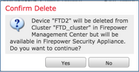
Clique no ícone de lixo ao lado da unidade de escravos, como mostrado na imagem.

A janela de confirmação é exibida. Selecione Sim para confirmar como mostrado na imagem.
Verificação:
- Do FMC, como mostrado na imagem.

- Da CLI do FXOS.
FPR9K-1-A# scope ssa
FPR9K-1-A /ssa # show app-instance
Application Name     Slot ID    Admin State     Operational State    Running Version Startup Version Cluster Oper State
-------------------- ---------- --------------- -------------------- --------------- --------------- ------------------
ftd                  1          Enabled         Online               6.0.1.1213      6.0.1.1213      In Cluster
ftd                  2          Enabled         Online               6.0.1.1213      6.0.1.1213      In Cluster
ftd                  3          Enabled         Online               6.0.1.1213      6.0.1.1213      In Cluster
- Na CLI do LINA (ASA).
firepower# show cluster info
Cluster FTD_cluster: On
    Interface mode: spanned
    This is "unit-1-1" in state MASTER
        ID        : 0
        Version   : 9.6(1)
        Serial No.: FLM19216KK6
        CCL IP    : 127.2.1.1
        CCL MAC   : 0015.c500.016f
        Last join : 21:51:03 CEST Aug 8 2016
        Last leave: N/A
Other members in the cluster:
    Unit "unit-1-3" in state SLAVE
        ID        : 1
        Version   : 9.6(1)
        Serial No.: FLM19206H7T
        CCL IP    : 127.2.1.3
        CCL MAC   : 0015.c500.018f
        Last join : 21:51:05 CEST Aug 8 2016
        Last leave: N/A
    Unit "unit-1-2" in state SLAVE
        ID        : 2
        Version   : 9.6(1)
        Serial No.: FLM19206H71
        CCL IP    : 127.2.1.2
        CCL MAC   : 0015.c500.019f
        Last join : 21:51:30 CEST Aug 8 2016
        Last leave: N/A
firepower#
Note: O dispositivo não foi registrado no FMC, mas ainda é um membro do cluster no FPR9300.
Verificar
Use esta seção para confirmar se a sua configuração funciona corretamente.
A verificação é concluída e abordada em tarefas individuais.
Troubleshoot
Atualmente, não existem informações disponíveis específicas sobre Troubleshooting para esta configuração.
Informações Relacionadas
- Todas as versões do guia de configuração do Cisco Firepower Management Center podem ser encontradas aqui:
https://www.cisco.com/c/en/us/td/docs/security/firepower/roadmap/firepower-roadmap.html#id_47280.
- Todas as versões dos guias de configuração do FXOS Chassis Manager e CLI podem ser encontradas aqui:
https://www.cisco.com/c/en/us/td/docs/security/firepower/fxos/roadmap/fxos-roadmap.html#pgfId-121950.
- O Cisco Global Technical Assistance Center (TAC) recomenda enfaticamente este guia visual para um conhecimento prático profundo sobre as tecnologias de segurança de próxima geração do Cisco Firepower, incluindo as mencionadas neste artigo:
http://www.ciscopress.com/title/9781587144806.
- Para todas as Notas técnicas de configuração e solução de problemas referentes às tecnologias Firepower.
https://www.cisco.com/c/en/us/support/security/defense-center/tsd-products-support-series-home.html.
Colaborado por engenheiros da Cisco
- Olha YakovenkoCisco TAC Engineer
- John LongCisco TAC Engineer
Contate a Cisco
- Abrir um caso de suporte

- (É necessário um Contrato de Serviço da Cisco)
 Feedback