ACI交换矩阵发现故障排除 — 多Pod发现
下载选项
非歧视性语言
此产品的文档集力求使用非歧视性语言。在本文档集中,非歧视性语言是指不隐含针对年龄、残障、性别、种族身份、族群身份、性取向、社会经济地位和交叉性的歧视的语言。由于产品软件的用户界面中使用的硬编码语言、基于 RFP 文档使用的语言或引用的第三方产品使用的语言,文档中可能无法确保完全使用非歧视性语言。 深入了解思科如何使用包容性语言。
关于此翻译
思科采用人工翻译与机器翻译相结合的方式将此文档翻译成不同语言,希望全球的用户都能通过各自的语言得到支持性的内容。 请注意:即使是最好的机器翻译,其准确度也不及专业翻译人员的水平。 Cisco Systems, Inc. 对于翻译的准确性不承担任何责任,并建议您总是参考英文原始文档(已提供链接)。
目录
简介
本文档介绍了解ACI多Pod发现并对其进行故障排除的步骤。
背景信息
本文档中的内容摘自 思科以应用为中心的基础设施故障排除(第二版) 书籍,特别是交换矩阵发现 — 多Pod发现 第章。
多Pod概述
ACI多Pod允许部署单个APIC集群来管理多个互连的ACI网络。这些单独的ACI网络称为“Pod”,每个Pod是常规的两层或三层主干 — 枝叶拓扑。单个APIC集群可以管理多个Pod。
多Pod设计还允许跨Pod扩展ACI交换矩阵策略,这些交换机可以实际存在于多个房间中,甚至可以跨远程数据中心位置。在多Pod设计中,在APIC控制器集群上定义的任何策略将自动可供所有Pod使用。
最后,多Pod设计增强了故障域隔离。事实上,每个Pod运行其自己的COOP、MP-BGP和IS-IS协议的实例,因此这些协议中的故障和问题都包含在Pod中,不能传播到其他Pod。
有关多Pod设计和最佳实践的详细信息,请参阅cisco.com上的“ACI多Pod白皮书”。
多Pod ACI交换矩阵的主要元素是枝叶和主干交换机、APIC控制器和IPN设备。
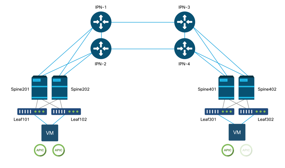
本示例深入到故障排除工作流程,了解与设置ACI多Pod交换矩阵相关的问题。本部分使用的参考拓扑如下图所示:
ACI多Pod参考拓扑
故障排除工作流程
验证ACI策略
访问策略
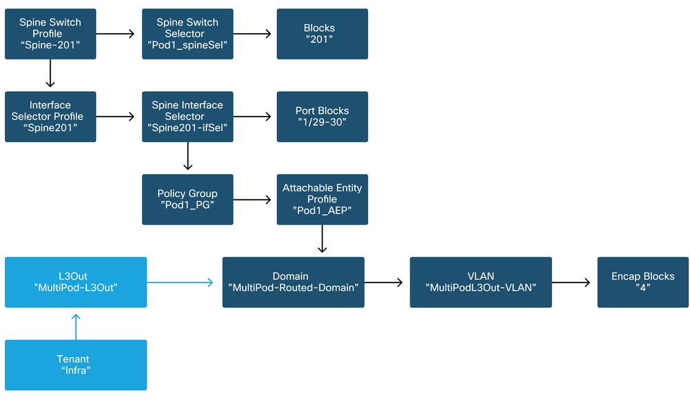
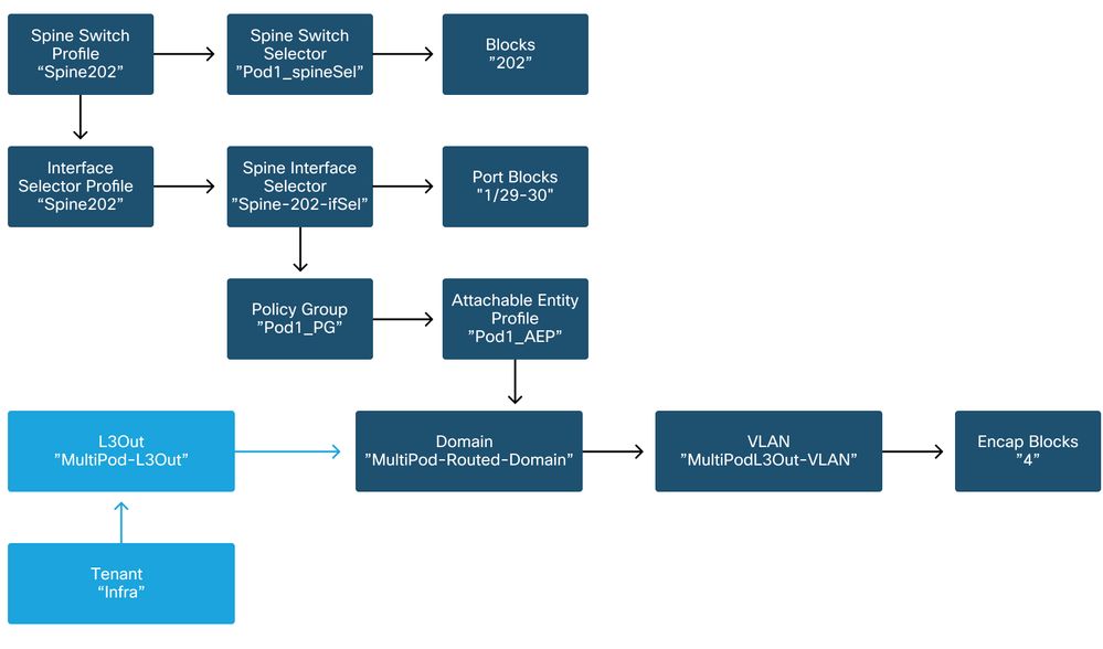
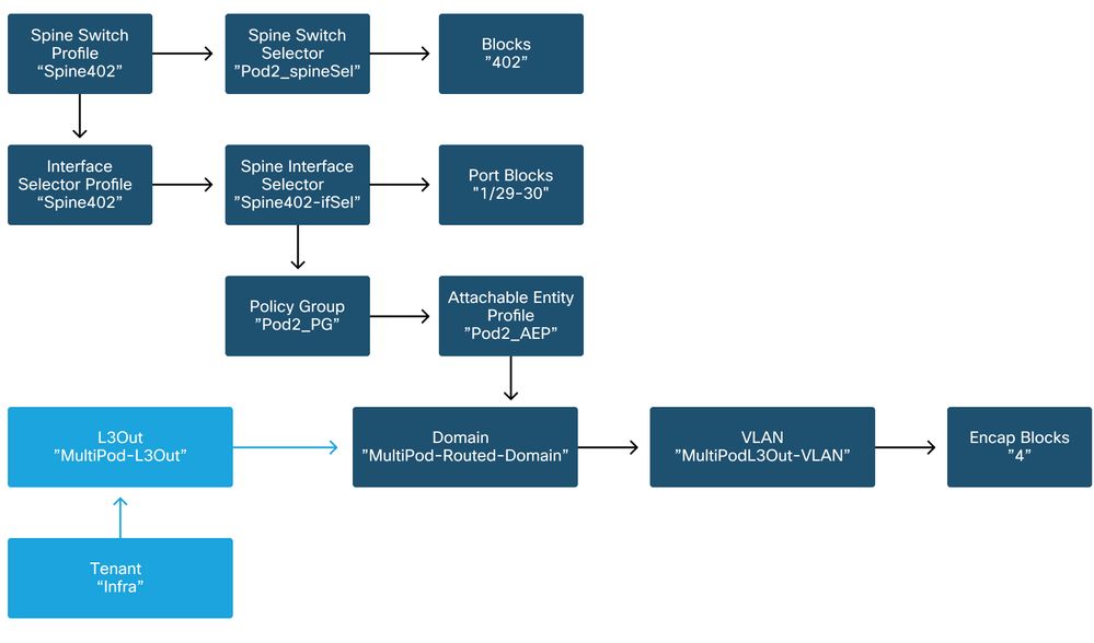
Multi-Pod使用L3Out以通过“infra”租户连接Pod。这意味着需要设置标准访问策略集以在面向IPN的主干端口上激活所需的多Pod L3Out封装(VLAN-4)。
可通过“添加Pod”向导配置访问策略,该向导应用于部署多Pod。使用向导后,可从APIC GUI验证部署的策略。如果未正确配置策略,则基础设施租户上会出现故障,并且从主干到IPN的连接可能未按预期工作。
验证主干节点上面向IPN的接口的访问策略定义时,可以引用以下方案:
主干201
主干202
主干401

主干402
在infra租户中,应根据以下方案配置多Pod L3Out:
基础设施租户中的多Pod L3Out
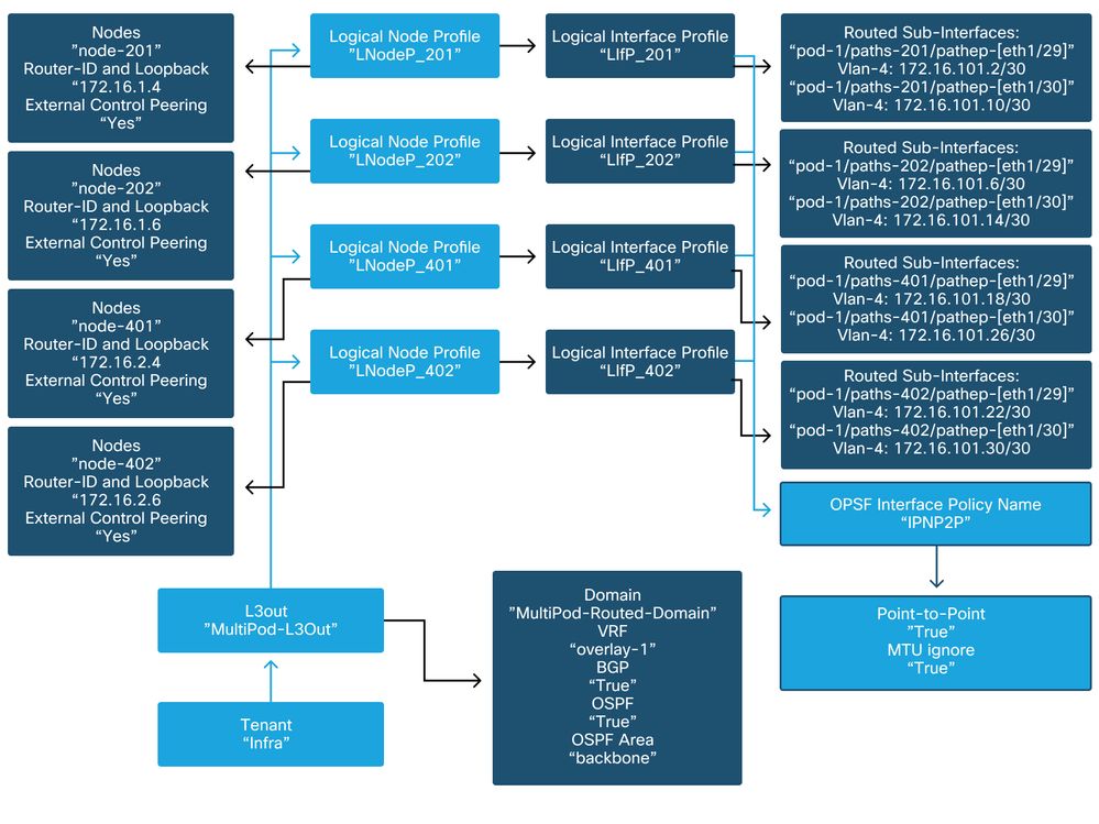
以下是多Pod L3Out逻辑接口配置文件配置的参考快照。路由器子接口定义应与主干201的如下图所示
基础设施L3Out中的逻辑接口配置文件

对于每个Pod,应有一个如下图中所定义的TEP池。请注意,APIC控制器将使用TEP池为overlay-1 VRF调配节点的IP地址。
Pod交换矩阵设置策略

交换矩阵外部连接策略默认值
确认在infra租户中定义并正确配置了“Fabric Ext Policy default”对象。此配置的示例如下图所示。
交换矩阵外部连接策略默认值

数据平面TEP

交换矩阵外部路由配置文件子网
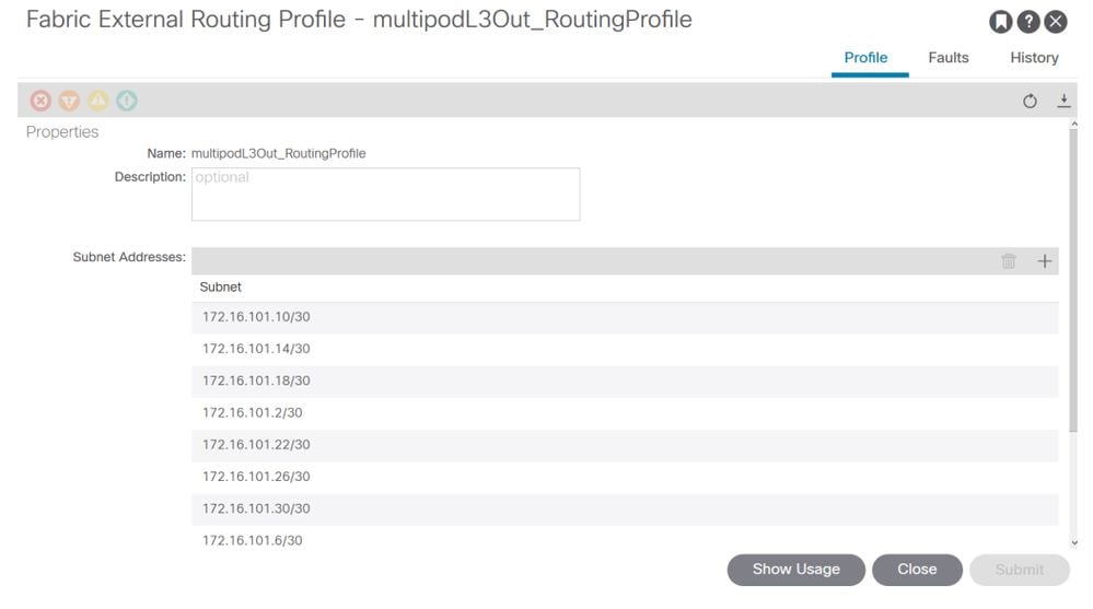
交换矩阵外部路由配置文件使用户能够验证定义的IPN的所有路由子网是否都在其中。
IPN验证
多Pod依赖于Pod间网络(IPN),该网络将提供POD到POD的连接。检验IPN配置是否正确就位非常重要。通常,配置有故障或缺失是发生故障时意外行为或流量丢弃的来源。本节将详细介绍IPN的配置。
在下一节中,请参阅以下IPN拓扑:
IPN拓扑
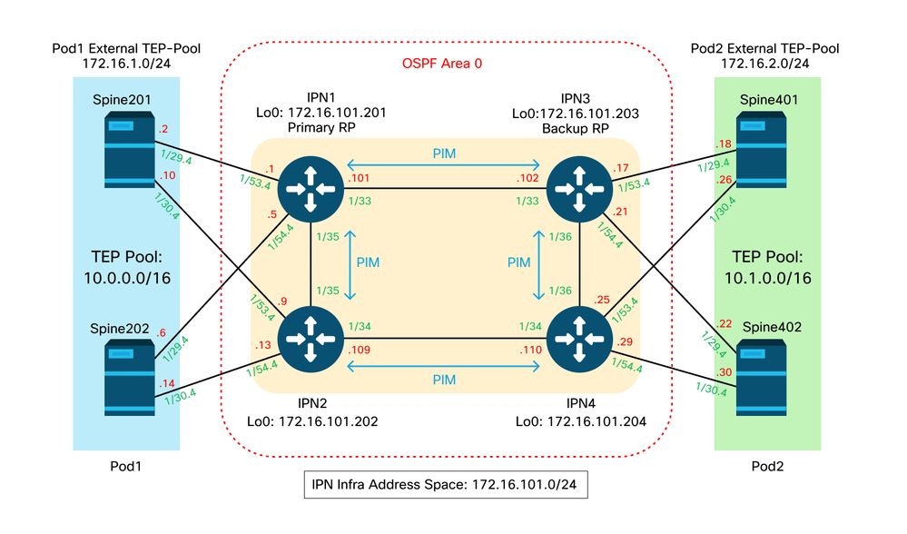
主干到IPN dot1q VLAN-4子接口连接
通过VLAN-4上的子接口实现了主干到IPN的点对点连接。此连接的第一个验证是测试主干与IPN设备之间的IP可达性。
为此,请确定正确的接口并检验其是否显示为up状态。
S1P1-Spine201# show ip int brief vrf overlay-1 | grep 172.16.101.2
eth1/29.29           172.16.101.2/30      protocol-up/link-up/admin-up

S1P1-Spine201# show ip interface  eth1/29.29
IP Interface Status for VRF "overlay-1"
eth1/29.29, Interface status: protocol-up/link-up/admin-up, iod: 67, mode: external
  IP address: 172.16.101.2, IP subnet: 172.16.101.0/30
  IP broadcast address: 255.255.255.255
  IP primary address route-preference: 0, tag: 0

S1P1-Spine201# show system internal ethpm  info interface Eth1/29.29
Ethernet1/29.29 - if_index: 0x1A01C01D
Router MAC address: 00:22:bd:f8:19:ff
Admin Config Information:
  state(up), mtu(9150), delay(1), vlan(4), cfg-status(valid)
  medium(broadcast)
Operational (Runtime) Information:
  state(up), mtu(9150), Local IOD(0x43), Global IOD(0x43), vrf(enabled)
  reason(None)
  bd_id(29)
Information from SDB Query (IM call)
  admin state(up), runtime state(up), mtu(9150),
  delay(1), bandwidth(40000000), vlan(4), layer(L3),
  medium(broadcast)
  sub-interface(0x1a01c01d) from parent port(0x1a01c000)/Vlan(4)
  Operational Bits:

User config flags:  0x1
  admin_router_mac(1)

Sub-interface FSM state(3)
No errors on sub-interface
Information from GLDB Query:
Router MAC address: 00:22:bd:f8:19:ff
检验接口启用后,现在测试点对点IP连接:
S1P1-Spine201# iping -V overlay-1 172.16.101.1
PING 172.16.101.1 (172.16.101.1) from 172.16.101.2: 56 data bytes
64 bytes from 172.16.101.1: icmp_seq=0 ttl=255 time=0.839 ms
64 bytes from 172.16.101.1: icmp_seq=1 ttl=255 time=0.719 ms
^C
--- 172.16.101.1 ping statistics ---
2 packets transmitted, 2 packets received, 0.00% packet loss
round-trip min/avg/max = 0.719/0.779/0.839 ms
如果存在任何连接问题,请验证远程IPN(IPN1)上的布线和配置。
IPN1# show ip interface brief | grep 172.16.101.1
Eth1/33              172.16.101.101  protocol-up/link-up/admin-up
Eth1/35              172.16.101.105  protocol-up/link-up/admin-up
Eth1/53.4            172.16.101.1    protocol-up/link-up/admin-up

IPN1# show run int Eth1/53.4
interface Ethernet1/53.4
description to spine 1pod1
mtu 9150
encapsulation dot1q 4
ip address 172.16.101.1/30
ip ospf cost 100
ip ospf network point-to-point
ip router ospf 1 area 0.0.0.0
ip pim sparse-mode
ip dhcp relay address 10.0.0.3
no shutdown
OSPF 配置
OSPF用作在ACI VRF“overlay-1”中将Pod1和Pod2连接在一起的路由协议。 以下内容可作为验证主干和IPN设备之间是否出现OSPF的通用流程参考。
S1P1-Spine201# show ip ospf neighbors vrf overlay-1
OSPF Process ID default VRF overlay-1
Total number of neighbors: 2
Neighbor ID     Pri State            Up Time  Address         Interface
172.16.101.201    1 FULL/ -          08:39:35 172.16.101.1    Eth1/29.29
172.16.101.202    1 FULL/ -          08:39:34 172.16.101.9    Eth1/30.30

S1P1-Spine201# show ip ospf  interface  vrf overlay-1
Ethernet1/29.29 is up, line protocol is up
   IP address 172.16.101.2/30, Process ID default VRF overlay-1, area backbone
   Enabled by interface configuration
   State P2P, Network type P2P, cost 1
   Index 67, Transmit delay 1 sec
   1 Neighbors, flooding to 1, adjacent with 1
   Timer intervals: Hello 10, Dead 40, Wait 40, Retransmit 5
     Hello timer due in 00:00:10
   No authentication
   Number of opaque link LSAs: 0, checksum sum 0
loopback0 is up, line protocol is up
   IP address 10.0.200.66/32, Process ID default VRF overlay-1, area backbone
   Enabled by interface configuration
   State LOOPBACK, Network type LOOPBACK, cost 1
 loopback14 is up, line protocol is up
   IP address 172.16.1.4/32, Process ID default VRF overlay-1, area backbone
   Enabled by interface configuration
   State LOOPBACK, Network type LOOPBACK, cost 1
 Ethernet1/30.30 is up, line protocol is up
   IP address 172.16.101.10/30, Process ID default VRF overlay-1, area backbone
   Enabled by interface configuration
   State P2P, Network type P2P, cost 1
   Index 68, Transmit delay 1 sec
   1 Neighbors, flooding to 1, adjacent with 1
   Timer intervals: Hello 10, Dead 40, Wait 40, Retransmit 5
     Hello timer due in 00:00:09
   No authentication
   Number of opaque link LSAs: 0, checksum sum 0

IPN1# show ip ospf  neighbors
OSPF Process ID 1 VRF default
Total number of neighbors: 5
Neighbor ID     Pri State            Up Time  Address         Interface
172.16.101.203    1 FULL/ -          4d12h    172.16.101.102  Eth1/33
172.16.101.202    1 FULL/ -          4d12h    172.16.101.106  Eth1/35
172.16.110.201    1 FULL/ -          4d12h    172.16.110.2    Eth1/48
172.16.1.4        1 FULL/ -          08:43:39 172.16.101.2    Eth1/53.4
172.16.1.6        1 FULL/ -          08:43:38 172.16.101.6    Eth1/54.4
当OSPF在所有主干和IPN设备之间启动时,可在IPN路由表中看到所有Pod TEP池。
IPN1# show ip ospf database 10.0.0.0 detail
       OSPF Router with ID (172.16.101.201) (Process ID 1 VRF default)
                Type-5 AS External Link States
LS age: 183
Options: 0x2 (No TOS-capability, No DC)
LS Type: Type-5 AS-External
Link State ID: 10.0.0.0 (Network address)
Advertising Router: 172.16.1.4
LS Seq Number: 0x80000026
Checksum: 0x2da0
Length: 36
Network Mask: /16
      Metric Type: 2 (Larger than any link state path)
      TOS: 0
      Metric: 20
      Forward Address: 0.0.0.0
      External Route Tag: 0
LS age: 183
Options: 0x2 (No TOS-capability, No DC)
LS Type: Type-5 AS-External
Link State ID: 10.0.0.0 (Network address)
Advertising Router: 172.16.1.6
LS Seq Number: 0x80000026
Checksum: 0x21aa
Length: 36
Network Mask: /16
      Metric Type: 2 (Larger than any link state path)
      TOS: 0
      Metric: 20
      Forward Address: 0.0.0.0
      External Route Tag: 0

IPN1# show ip ospf database 10.1.0.0 detail
     OSPF Router with ID (172.16.101.201) (Process ID 1 VRF default)
                Type-5 AS External Link States
LS age: 1779
Options: 0x2 (No TOS-capability, No DC)
LS Type: Type-5 AS-External
Link State ID: 10.1.0.0 (Network address)
Advertising Router: 172.16.2.4
LS Seq Number: 0x80000022
Checksum: 0x22ad
Length: 36
Network Mask: /16
      Metric Type: 2 (Larger than any link state path)
      TOS: 0
      Metric: 20
      Forward Address: 0.0.0.0
      External Route Tag: 0
LS age: 1780
Options: 0x2 (No TOS-capability, No DC)
LS Type: Type-5 AS-External
Link State ID: 10.1.0.0 (Network address)
Advertising Router: 172.16.2.6
LS Seq Number: 0x80000022
Checksum: 0x16b7
Length: 36
Network Mask: /16
      Metric Type: 2 (Larger than any link state path)
      TOS: 0
      Metric: 20
      Forward Address: 0.0.0.0
      External Route Tag: 0

IPN1# show ip route 10.0.0.0
IP Route Table for VRF "default"
'*' denotes best ucast next-hop
'**' denotes best mcast next-hop
'[x/y]' denotes [preference/metric]
'%<string>' in via output denotes VRF <string>

10.0.0.0/16, ubest/mbest: 2/0
*via 172.16.101.2, Eth1/53.4, [110/20], 08:39:17, ospf-1, type-2
*via 172.16.101.6, Eth1/54.4, [110/20], 08:39:17, ospf-1, type-2

IPN1# show ip route 10.1.0.0
IP Route Table for VRF "default"
'*' denotes best ucast next-hop
'**' denotes best mcast next-hop
'[x/y]' denotes [preference/metric]
'%<string>' in via output denotes VRF <string>

10.1.0.0/16, ubest/mbest: 1/0
*via 172.16.101.102, Eth1/33, [110/20], 08:35:25, ospf-1, type-2
请注意,对于远程Pod(Pod2)的IPN1,在“show ip route”命令中仅显示最佳路由。
DHCP中继配置
交换机节点使用指向APIC的DHCP接收其基础设施TEP地址。所有APIC通常都会收到发现,但它是第一个接收发现并提交TEP地址分配提议的APIC。要在多Pod场景中解决此问题,请在IPN上配置DHCP中继以接收发现结果并将其单播到APIC。通常,使用指向所有APIC的IP帮助程序配置所有面向脊柱的IPN接口。如果由于重新布线、备用APIC故障切换或者任何涉及APIC移至新Pod的其他情况,这将对IPN配置进行未来验证。
在本场景中,这意味着配置IPN1 Eth1/53.4和Eth1/54.4的IP帮助程序指向所有APIC:
interface Ethernet1/53.4
 description to  spine 1pod1
 mtu 9150
 encapsulation dot1q 4
 ip address 172.16.101.1/30
 ip ospf cost 100
 ip ospf network point-to-point
 ip router ospf 1 area 0.0.0.0
 ip pim sparse-mode
 ip dhcp relay address 10.0.0.1
 ip dhcp relay address 10.0.0.2
 ip dhcp relay address 10.0.0.3
 no shutdown

interface Ethernet1/54.4
 description to  spine 2pod1
 mtu 9150
 encapsulation dot1q 4
 ip address 172.16.101.5/30
 ip ospf cost 100
 ip ospf network point-to-point
 ip router ospf 1 area 0.0.0.0
 ip pim sparse-mode
 ip dhcp relay address 10.0.0.1
 ip dhcp relay address 10.0.0.2
 ip dhcp relay address 10.0.0.3
 no shutdown
从IPN3:
interface Ethernet1/53.4
 description to  spine 1pod2
 mtu 9150
 encapsulation dot1q 4
 ip address 172.16.101.17/30
 ip ospf cost 100
 ip ospf network point-to-point
 ip router ospf 1 area 0.0.0.0
 ip pim sparse-mode
 ip dhcp relay address 10.0.0.1
 ip dhcp relay address 10.0.0.2
 ip dhcp relay address 10.0.0.3
 no shutdown

interface Ethernet1/54.4
 description to  spine 2pod2
 mtu 9150
 encapsulation dot1q 4
 ip address 172.16.101.21/30
 ip ospf cost 100
 ip ospf network point-to-point
 ip router ospf 1 area 0.0.0.0
 ip pim sparse-mode
 ip dhcp relay address 10.0.0.1
 ip dhcp relay address 10.0.0.2
 ip dhcp relay address 10.0.0.3
 no shutdown
MTU
如果主干和IPN设备之间没有启动OSPF(EXCHANGE或EXSTART),请确保验证设备之间的MTU匹配。
RP配置
使用PIM BiDir,交汇点(RP)不是数据路径的一部分。对于功能组播,每个IPN设备只需要有一个到RP地址的路由。可使用虚拟RP配置实现冗余。在这种情况下,任播RP不是有效的冗余方法,因为没有通过组播源发现协议(MSDP)进行交换的源。
在虚拟RP设计中,RP是可到达子网中不存在的地址。在下面的配置中,假设APIC初始设置中配置的组播范围是默认的225.0.0.0/15。如果在APIC初始设置中更改了该范围,则必须调整IPN配置。
下面的loopback1是phantom-rp loopback。必须将其注入OSPF;但是,它不能用作OPSF路由器ID。必须使用单独的环回(loopback0)。
IPN1配置:
interface loopback1
 description IPN1-RP-Loopback
 ip address 172.16.101.221/30
 ip ospf network point-to-point
 ip router ospf 1 area 0.0.0.0
 ip pim sparse-mode
ip pim rp-address 172.16.101.222 group-list 225.0.0.0/15 bidir
ip pim rp-address 172.16.101.222 group-list 239.255.255.240/32 bidir
IPN2配置:
ip pim rp-address 172.16.101.222 group-list 225.0.0.0/15 bidir
ip pim rp-address 172.16.101.222 group-list 239.255.255.240/32 bidir
IPN3配置:
interface loopback1
 description IPN3-RP-Loopback
 ip address 172.16.101.221/29
 ip ospf network point-to-point
 ip router ospf 1 area 0.0.0.0
 ip pim sparse-mode
ip pim rp-address 172.16.101.222 group-list 225.0.0.0/15 bidir
ip pim rp-address 172.16.101.222 group-list 239.255.255.240/32 bidir
IPN4配置:
ip pim rp-address 172.16.101.222 group-list 225.0.0.0/15 bidir
ip pim rp-address 172.16.101.222 group-list 239.255.255.240/32 bidir
环回的子网掩码不能是/32。要在幻影RP设计中将IPN1用作主要设备,请使用/30子网掩码来利用OSPF拓扑中首选的最具体路由。IPN3将是虚拟RP设计中的辅助设备,因此使用/29子网掩码使其成为不太具体的路由。只有在发生某些操作以停止OSPF拓扑中现有的/30和后续存在的/29时,才会使用/29。
排除连接交换矩阵的第一台远程Pod主干故障
以下步骤概述了第一台远程Pod主干加入交换矩阵的过程:
- 主干将在面向IPN的子接口上执行DHCP。DHCP中继配置会将此发现传送到APIC。如果脊柱已添加到交换矩阵成员中,APIC将做出响应。提供的IP地址是在多可配置设备L3Out上配置的IP地址。
- 主干将安装一条到DHCP服务器的路由,该DHCP服务器将IP地址作为静态路由提供到点对点接口的另一端。
- 主干将通过静态路由从APIC下载引导程序文件。
- 主干将根据引导程序文件进行配置,以启动VTEP、OSPF和BGP以加入交换矩阵。
从APIC验证是否已正确配置要提供的L3Out IP:(我们的Spine 401具有串行22472/FCV)
bdsol-aci37-apic1# moquery -c dhcpExtIf

# dhcp.ExtIf
ifId         : eth1/30
childAction  :
dn           : client-[FDO22472FCV]/if-[eth1/30]
ip           : 172.16.101.26/30
lcOwn        : local
modTs        : 2019-10-01T09:51:29.966+00:00
name         :
nameAlias    :
relayIp      : 0.0.0.0
rn           : if-[eth1/30]
status       :
subIfId      : unspecified

# dhcp.ExtIf
ifId         : eth1/29
childAction  :
dn           : client-[FDO22472FCV]/if-[eth1/29]
ip           : 172.16.101.18/30
lcOwn        : local
modTs        : 2019-10-01T09:51:29.966+00:00
name         :
nameAlias    :
relayIp      : 0.0.0.0
rn           : if-[eth1/29]
status       :
subIfId      : unspecified
验证面向IPN的接口是否收到与基础设施租户中完成的L3Out配置相匹配的预期IP地址。
S1P2-Spine401# show ip interface brief | grep eth1/29
eth1/29              unassigned           protocol-up/link-up/admin-up
eth1/29.29           172.16.101.18/30     protocol-up/link-up/admin-up
现在,已经建立了从主干到APIC的IP连接,并且可以验证通过ping的连接:
S1P2-Spine401# iping -V overlay-1 10.0.0.1
PING 10.0.0.1 (10.0.0.1) from 172.16.101.18: 56 data bytes
64 bytes from 10.0.0.1: icmp_seq=0 ttl=60 time=0.345 ms
64 bytes from 10.0.0.1: icmp_seq=1 ttl=60 time=0.294 ms
^C
--- 10.0.0.1 ping statistics ---
2 packets transmitted, 2 packets received, 0.00% packet loss
round-trip min/avg/max = 0.294/0.319/0.345 ms
现在,主干将启动OSPF到IPN并为路由器ID设置环回:
S1P2-Spine401# show ip ospf neighbors vrf overlay-1
OSPF Process ID default VRF overlay-1
Total number of neighbors: 2
Neighbor ID     Pri State            Up Time  Address         Interface
172.16.101.204    1 FULL/ -          00:04:16 172.16.101.25   Eth1/30.30
172.16.101.203    1 FULL/ -          00:04:16 172.16.101.17   Eth1/29.29

S1P2-Spine401# show ip ospf  interface  vrf overlay-1
loopback8 is up, line protocol is up
   IP address 172.16.2.4/32, Process ID default VRF overlay-1, area backbone
   Enabled by interface configuration
   State LOOPBACK, Network type LOOPBACK, cost 1
 Ethernet1/30.30 is up, line protocol is up
   IP address 172.16.101.26/30, Process ID default VRF overlay-1, area backbone
   Enabled by interface configuration
   State P2P, Network type P2P, cost 1
   Index 68, Transmit delay 1 sec
   1 Neighbors, flooding to 1, adjacent with 1
   Timer intervals: Hello 10, Dead 40, Wait 40, Retransmit 5
     Hello timer due in 00:00:07
   No authentication
   Number of opaque link LSAs: 0, checksum sum 0
Ethernet1/29.29 is up, line protocol is up
   IP address 172.16.101.18/30, Process ID default VRF overlay-1, area backbone
   Enabled by interface configuration
   State P2P, Network type P2P, cost 1
   Index 67, Transmit delay 1 sec
   1 Neighbors, flooding to 1, adjacent with 1
   Timer intervals: Hello 10, Dead 40, Wait 40, Retransmit 5
     Hello timer due in 00:00:04
   No authentication
   Number of opaque link LSAs: 0, checksum sum 0
主干现在将通过DHCP接收其PTEP:
S1P2-Spine401# show ip interface vrf overlay-1 | egrep -A 1 status
lo0, Interface status: protocol-up/link-up/admin-up, iod: 4, mode: ptep
IP address: 10.1.88.67, IP subnet: 10.1.88.67/32
主干将从发现移至活动,并且已完全发现:
bdsol-aci37-apic1# acidiag fnvread
     ID   Pod ID                 Name    Serial Number         IP Address    Role        State   LastUpdMsgId
--------------------------------------------------------------------------------------------------------------
    101        1         S1P1-Leaf101      FDO224702JA     10.0.160.64/32    leaf         active   0
    102        1         S1P1-Leaf102      FDO223007G7     10.0.160.67/32    leaf         active   0
    201        1        S1P1-Spine201      FDO22491705     10.0.160.65/32   spine         active   0
    202        1        S1P1-Spine202      FDO224926Q9     10.0.160.66/32   spine         active   0
    401        2        S1P2-Spine401      FDO22472FCV      10.1.88.67/32   spine         active   0
请注意,我们只能发现连接了至少一个枝叶交换机的远程主干。
检验剩余的枝叶和主干交换机
Pod的其余部分现已按照正常的Pod启动过程被发现,如“初始交换矩阵设置”一节所述。
检查远程Pod APIC
要发现第3个APIC,请遵循以下流程:
- 枝叶301根据LLDP(与单个Pod机箱相同)创建到直连APIC(APIC3)的静态路由。远程APIC将从POD1 IP池接收IP地址。我们将此路由创建为/32。
- 枝叶301使用IS-IS向Spine401和Spine402通告此路由(与单个Pod机箱相同)
- Spine401和Spine402将此路由重分布到OSPF中并指向IPN
- Spine201和Spine202在Pod1中将此路由从OSPF重分布到IS-IS
- 现在,APIC3与APIC1和APIC2之间已建立连接
- APIC3现在可以加入集群
要确认,请使用以下检查:
枝叶301根据LLDP(与单Pod机箱相同)创建到直连APIC(APIC3)的静态路由
S1P2-Leaf301# show ip route 10.0.0.3 vrf overlay-1
IP Route Table for VRF "overlay-1"
'*' denotes best ucast next-hop
'**' denotes best mcast next-hop
'[x/y]' denotes [preference/metric]
'%<string>' in via output denotes VRF <string>

10.0.0.3/32, ubest/mbest: 2/0
   *via 10.1.88.64, eth1/50.14, [115/12], 00:07:21, isis-isis_infra, isis-l1-ext
   *via 10.1.88.67, eth1/49.13, [115/12], 00:07:15, isis-isis_infra, isis-l1-ext
    via 10.0.0.3, vlan9, [225/0], 07:31:04, static
枝叶301使用IS-IS向Spine401和Spine402通告此路由(与单个Pod机箱相同)
Spine401和Spine402将此路由泄漏到OSPF中以向IPN发送
S1P2-Spine401# show ip route 10.0.0.3 vrf overlay-1
IP Route Table for VRF "overlay-1"
'*' denotes best ucast next-hop
'**' denotes best mcast next-hop
'[x/y]' denotes [preference/metric]
'%<string>' in via output denotes VRF <string>

10.0.0.3/32, ubest/mbest: 1/0
    *via 10.1.88.65, eth1/2.35, [115/11], 00:17:38, isis-isis_infra, isis-l1-ext  S1P2-Spine401#

IPN3# show ip route 10.0.0.3
IP Route Table for VRF "default"
'*' denotes best ucast next-hop
'**' denotes best mcast next-hop
'[x/y]' denotes [preference/metric]
'%<string>' in via output denotes VRF <string>

10.0.0.3/32, ubest/mbest: 2/0
    *via 172.16.101.18, Eth1/53.4, [110/20], 00:08:05, ospf-1, type-2
    *via 172.16.101.22, Eth1/54.4, [110/20], 00:08:05, ospf-1, type-2

S1P1-Spine201# show ip route vrf overlay-1 10.0.0.3
IP Route Table for VRF "overlay-1"
'*' denotes best ucast next-hop
'**' denotes best mcast next-hop
'[x/y]' denotes [preference/metric]
'%<string>' in via output denotes VRF <string>

10.0.0.3/32, ubest/mbest: 2/0
    *via 172.16.101.1, eth1/29.29, [110/20], 00:08:59, ospf-default, type-2
    *via 172.16.101.9, eth1/30.30, [110/20], 00:08:59, ospf-default, type-2
    via 10.0.160.64, eth1/1.36, [115/12], 00:18:19, isis-isis_infra, isis-l1-ext
    via 10.0.160.67, eth1/2.35, [115/12], 00:18:19, isis-isis_infra, isis-l1-ext
现在,APIC3与APIC1和APIC2之间已建立连接
APIC3现在可以加入集群
apic1# show controller
Fabric Name          : POD37
Operational Size     : 3
Cluster Size         : 3
Time Difference      : 133
Fabric Security Mode : PERMISSIVE
 ID    Pod   Address          In-Band IPv4     In-Band IPv6               OOB IPv4         OOB IPv6                        Version             Flags  Serial Number     Health
----  ----  ---------------  ---------------  -------------------------  ---------------  ------------------------------  ------------------  -----  ----------------  ------------------
1*    1     10.0.0.1         0.0.0.0          fc00::1                    10.48.176.57     fe80::d6c9:3cff:fe51:cb82       4.2(1i)             crva-  WZP22450H82       fully-fit
2     1     10.0.0.2         0.0.0.0          fc00::1                    10.48.176.58     fe80::d6c9:3cff:fe51:ae22       4.2(1i)             crva-  WZP22441AZ2       fully-fit
3     2     10.0.0.3         0.0.0.0          fc00::1                    10.48.176.59     fe80::d6c9:3cff:fe51:a30a       4.2(1i)             crva-  WZP22441B0T       fully-fit
Flags - c:Commissioned | r:Registered | v:Valid Certificate | a:Approved | f/s:Failover fail/success
(*)Current (~)Standby (+)AS
从APIC1 ping Pod2中的远程设备,以通过以下ping检验连接:(确保从APIC1案例10.0.0.1中的本地接口发出)
apic1# ping 10.0.0.3 -I 10.0.0.1
PING 10.0.0.3 (10.0.0.3) from 10.0.0.1 : 56(84) bytes of data.
64 bytes from 10.0.0.3: icmp_seq=1 ttl=58 time=0.132 ms
64 bytes from 10.0.0.3: icmp_seq=2 ttl=58 time=0.236 ms
64 bytes from 10.0.0.3: icmp_seq=3 ttl=58 time=0.183 ms
^C
--- 10.0.0.3 ping statistics ---
3 packets transmitted, 3 received, 0% packet loss, time 2048ms
rtt min/avg/max/mdev = 0.132/0.183/0.236/0.045 ms
故障排除情况
主干无法ping通IPN
最可能的原因包括:
- ACI访问策略配置错误。
- IPN配置中存在配置错误。
请参阅本章中的“故障排除工作流程”并复习:
- 检验ACI策略。
- IPN验证。
远程主干未连接交换矩阵
最可能的原因包括:
- IPN网络上的DHCP中继问题。
- 通过IPN网络实现主干到APIC IP的可达性。
请参阅本章中的“故障排除工作流程”并复习:
- 检验ACI策略。
- IPN验证。
- 排除第1个交换矩阵连接故障。
确保验证至少有一个枝叶连接到远程主干,并且该主干与此枝叶具有LLDP邻接关系。
Pod2中的APIC未连接交换矩阵
这通常是由假设远程Pod枝叶和主干交换机能够正确加入交换矩阵的APIC初始设置对话框中的错误造成的。在正确的设置中,预期以下“avread”输出(工作APIC3加入场景):
apic1# avread
Cluster:
-------------------------------------------------------------------------
fabricDomainName        POD37
discoveryMode           PERMISSIVE
clusterSize             3
version                 4.2(1i)
drrMode                 OFF
operSize                3
APICs:
-------------------------------------------------------------------------
                   APIC 1                  APIC 2                  APIC 3
version           4.2(1i)                 4.2(1i)                 4.2(1i)
address           10.0.0.1                10.0.0.2                10.0.0.3
oobAddress        10.48.176.57/24         10.48.176.58/24         10.48.176.59/24
routableAddress   0.0.0.0                 0.0.0.0                 0.0.0.0
tepAddress        10.0.0.0/16             10.0.0.0/16             10.0.0.0/16
podId             1                       1                       2
chassisId         7e34872e-.-d3052cda     84debc98-.-e207df70     89b73e48-.-f6948b98
cntrlSbst_serial  (APPROVED,WZP22450H82)  (APPROVED,WZP22441AZ2)  (APPROVED,WZP22441B0T)
active            YES                     YES                     YES
flags             cra-                    cra-                    cra-
health            255                     255                     255
请注意,APIC3(在远程Pod中)配置了PodId 2和Pod1的tepAddress。
使用以下命令验证原始APIC3设置设置:
apic3# cat /data/data_admin/sam_exported.config
Setup for Active and Standby APIC
fabricDomain = POD37
fabricID = 1
systemName =bdsol-aci37-apic3
controllerID = 3
tepPool = 10.0.0.0/16
infraVlan = 3937
clusterSize = 3
standbyApic = NO
enableIPv4 = Y
enableIPv6 = N
firmwareVersion = 4.2(1i)
ifcIpAddr = 10.0.0.3
apicX = NO
podId = 2
oobIpAddr = 10.48.176.59/24
如果发生错误,请登录APIC3并执行“acidiag touch setup”和“acidiag reboot”。
POD到POD BUM流量不起作用
最可能的原因包括:
- IP网络中缺少RP
- ACI交换矩阵无法访问RP IPN设备上的常规组播配置错误
请参阅本章中的“故障排除工作流程”并复习:
- IPN验证
另请确保其中一个IPN RP设备处于联机状态。
1个IPN设备发生故障后,BUM流量将被丢弃
如故障排除工作流程中的IPN验证中所述,使用虚拟RP来保证当主RP关闭时,辅助RP可用。确保复习“IPN验证”部分并验证正确的验证。
Pod间终端连接在同一EPG内断开
这很可能是由多Pod设置中的错误配置造成的,请确保验证故障排除工作流程并验证整个流程。如果这看起来正常,请参阅“交换矩阵内转发”一章中的“多Pod转发”部分,以进一步解决此问题。
修订历史记录
| 版本 | 发布日期 | 备注 |
|---|---|---|
1.0 |
08-Aug-2022 |
初始版本 |
由思科工程师提供
- ACI Escalation Engineers
- Technical Marketing
 反馈
反馈