DLSw故障排除:SDLC
目录
简介
本文档帮助您排除在连接同步数据链路控制(SDLC)的终端设备连接到数据中心(例如,通过数据链路交换(DLSw))时网络中可能出现的问题。
先决条件
要求
本文档没有任何特定的要求。
使用的组件
本文档不限于特定的软件或硬件版本。
本文档中的信息都是基于特定实验室环境中的设备编写的。本文档中使用的所有设备最初均采用原始(默认)配置。如果您使用的是真实网络,请确保您已经了解所有命令的潜在影响。
规则
有关文件规则的更多信息请参见“ Cisco技术提示规则”。
排除SDLC故障
在路由器上发出show interface serial x命令,开始排除SDLC故障。此命令的输出包含可能帮助您查找问题的信息。
Serial1/0 is up, line protocol is up
!--- If line is down/down, then check CLOCKING. !--- If line is up/down, then check NRZI_ENCODING. !--- If line is cycling between up/up and up/down, then check DUPLEX. !--- A modem sharing device (MSD) uses full duplex.
Hardware is CD2430 in sync mode
Description SDLC PU2.1 PRIMARY
MTU 1500 bytes, BW 128 Kbit, DLY 20000 usec, rely 255/255, load 1/255
Encapsulation SDLC, loopback not set
Router link station role: PRIMARY (DCE)
!--- DCE has to provide the clock. It is responsible for raising DCD, CTS, !--- and DSR. Issue the show controllers command to check DTE, DCE, and !--- cable type.
Router link station metrics:
slow-poll 10 seconds
T1 (reply time out) 3000 milliseconds
!--- The sdlc t1
is a !--- numeric value in milliseconds between 1 and 64000 (default is 3000).
N1 (max frame size) 12016 bits
!--- The sdlc n1
is a numeric value from 1 to 12000 !--- (default is 12000).
N2 (retry count) 20
!--- The sdlc n2
!--- is a numeric value between 1 and 255 (default is 20).
poll-pause-timer 200 milliseconds
!--- Set this with the sdlc poll-pause-timer
is a numeric value in milliseconds from 1 to 10000. !--- Set this value to a minimum of 2000 before you run SDLC debugs; otherwise, !--- you will flood the console with SDLC polling messages.
poll-limit-value 1
!--- Set this with the sdlc poll-limit-value
!--- is a numeric value from 1 to 10. !--- Use this command on multidrops to determine the number of polls that are !--- dedicated to each secondary device. Higher value allows a single secondary !--- to send more data but can decrease overall secondary servicing efficiency.
k (windowsize) 1
modulo 8
!--- Set K with the sdlc k
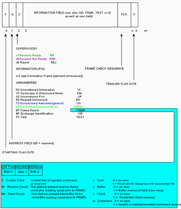
is a !--- numeric value of 1 through 7 (if modulo 7) or 1 through 127 (if modulo 128). !--- rrrz sss0 !--- rrr = Frame number of the block that is expected to be received next !--- (rrrrrrr if modulo 128) !--- z = Poll/Final bit, which may be 0 or 1. !--- sss = Frame number of the block that is expected to be sent next !--- (sssssss if modulo 128) !--- The K value determines how many frames after which the poll bit is set to 1, !--- which indicates that it is the other side???s turn to send.
sdlc vmac: 4000.1555.21--
sdlc addr 01 state is CONNECT
!--- Refer to SDLC States
.
cls_state is CLS_IN_SESSION
!--- See Table 1 ??? CLS States.
VS 6, VR 6, Remote VR 6, Current retransmit count 0
Hold queue: 0/200 IFRAMEs 2649/683
TESTs 0/0 XIDs 0/0, DMs 0/0 FRMRs 0/0
!--- FRMRs could indicate a bug in the end station SDLC emulation package. !--- Check the values in the FRMR frame against the FRMR frame description.
RNRs 1797153/2291 SNRMs 222/0 DISC/RDs 12/0 REJs 0/0
!--- If you see a steady increase in RNRs, then check for congestion on the DLSw !--- peer (the value under the TCP column in show dlsw peer command output). !--- If RNRs are greater than 50 percent of the default TCP queue depth 200, then !--- there is congestion.
Poll: clear, Poll count: 0, ready for poll, chain: 01/01
Last input 00:00:00, output 00:00:00, output hang never
Last clearing of "show interface" counters never
Queueing strategy: fifo
Output queue 0/40, 0 drops; input queue 0/75, 0 drops
!--- Check that the input and output queues are not wedged (41/40 or 76/75). !--- If the queue is wedged, then the router usually must be reloaded to recover.
5 minute input rate 0 bits/sec, 4 packets/sec
5 minute output rate 0 bits/sec, 4 packets/sec
2857443 packets input, 5738306 bytes, 0 no buffer
Received 409483 broadcasts, 0 runts, 0 giants, 0 throttles
1 input errors, 0 CRC, 0 frame, 0 overrun, 0 ignored, 1 abort
!--- Giants and input errors might indicate a wrong NRZI value (NRZI-ENCODING).
2857874 packets output, 6029620 bytes, 0 underruns
0 output errors, 0 collisions, 60523 interface resets
0 output buffer failures, 0 output buffers swapped out
53 carrier transitions
DCD=up DSR=up DTR=up RTS=down CTS=up
!--- RTS and CTS are always up, with full duplex. !--- RTS and CTS will cycle between up and down, with half duplex.
表1 ???CLS状态
| 状态 | 含义 |
|---|---|
| CLS_STN_CLOSED | 尚未启动任何行激活过程。 |
| CLS_ROSCNF_PEND | ReqOpenStn已发送到PU;正在等待ReqOpenStnCfm。 |
| CLS_STN_OPENED | 从PU接收ReqOpenStnCfm。 |
| CLS_CONNECT_RSP_PEND | 已发送SNRM;等待PU的UA。 |
| CLS_DISCCNF_PEND | PU发送DISK(如果为主)或RDISC(如果辅助)。 |
| CLS_CONNECT_REQ_PEND | 正在等待连接响应。 |
| CLS_FULL_XID_PEND | 正在等待对发送的空XID的响应。 |
| CLS_CONNECTED_IND_PEND | 从DLU收到Connect.Rsp。 |
| CLS_DISK_IND_SENT | Disconnect.Ind已发送。 |
| CLS_IN_SESSION | 电路建立已完成。 |
| CLS_CLOSING | 思科链路服务(CLS)处于关闭状态。 |
PU类型
对于SDLC连接的控制器,必须了解正在使用的物理单元(PU)类型(例如,PU 2.0或PU 2.1)和SDLC角色。
表2显示了一些最常见的设备及其代表的PU类型。PU类型确定应采用的配置,如PU 2中的“SDLC站角色设置为辅助”部分所示。
表2 ???设备PU类型| 设备 | PU类型 |
|---|---|
| 5294 | 1 |
| 5394 | 1 |
| 5394 +RPQ 8Q0775 | 2.1 |
| 5494 | 2.1 |
| 3276 | 2.0 |
| 3274 | 2.0 |
| 3174 | 2.0 / 2.1 |
| 3745 | 4 |
| 3172 | 无PU XCA节点 |
| S/38 | 2.0 |
| 36XX | 2.0 |
| Netware/SAA | 2.0 / 2.1 |
| SNA服务器NT | 2.0 / 2.1 |
PU 2,SDLC站角色设置为辅助
interface serial x

encapsulation sdlc
sdlc role primary

!--- Assumes SDLC station role secondary for the attached SDLC controller.

sdlc vmac 1234.3174.0000

!--- Virtual MAC address given to the SDLC controller, which has the !--- SDLC address (D2) appended to it.


!--- For more information about the sdlc vmac command, refer to !--- LLC2 and SDLC Commands.

sdlc address D2

!--- SDLC address obtained from SDLC controller configuration.

sdlc xid D2 01730020

!--- D2 is the SDLC address, and 01730020 is the IDBLK and IDNUM, which is !--- obtained from the Switched Major Node on the host.

sdlc partner 1000.5aed.1f53 D2

!--- 1000.5aed.1f53 is the MAC address of the host, and D2 is the SDLC address.

sdlc dlsw D2
PU 2,SDLC站角色设置为主
interface serial x

sdlc role secondary
sdlc vmac 1234.3174.0000
sdlc address D2
sdlc xid D2 01730020
sdlc partner 1000.5aed.1f53 D2
sdlc dlsw D2
节点类型2.1,SDLC站角色设置为可协商或主
interface serial x

encapsulation sdlc
sdlc role none
sdlc vmac 1234.3174.0000
sdlc address D2
sdlc partner 1000.5aed.1f53 D2
sdlc dlsw D2
节点类型2.1,SDLC站角色设置为辅助
interface serial x

encapsulation sdlc
sdlc role prim-xid-poll
sdlc vmac 1234.3174.0000
sdlc address D2
sdlc partner 1000.5aed.1f53 D2
sdlc dlsw D2
注:对于PU 2.0或PU 2.1的多丢弃SDLC,以及PU 2.0和PU 2.1的组合,请参阅配置数据链路交换Plus的DLSw+和SDLC多丢弃支持配置示例部分。
PU 4.0,带SDLC
interface serial x

no ip address
encapsulation sdlc
no keepalive
clock rate 19200
sdlc vmac 4000.3745.0100
sdlc address 01 seconly
sdlc partner 4000.3745.2176 01
sdlc dlsw 1
有关SDLC到逻辑链路控制的详细信息,请参阅PU4/5设备的DLSw+ FID4 LLC2到SDLC的转换(格式指示器4(FID4)帧的类型2(LLC2)转换)。
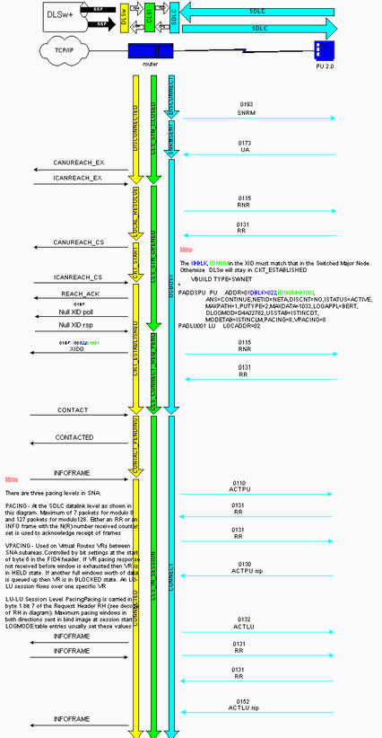
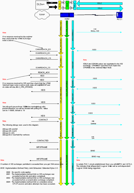
思科链路服务与SDLC之间有直接关系。对于思科链路服务,在未编号确认(UA)确认设置正常响应模式(SNRM)之前,不会发生任何更改。 获得UA后,路由器会向SDLC站发送接收器未就绪(RNR, USBUSY),以在DLSw将DLSw电路与主机(SDLC角色主要)连接时保持静态。 SDLC代码向思科链路服务代码内部发送空交换标识(XID),以启动此操作。可以看到以下思科链路服务状态:
-
CLS_STN_CLOSED???CANUREACH资源管理器(CUR-ex)被发送到DLSw对等体,但尚未收到ICANREACH资源管理器(ICR-ex)响应。问题可能是MAC地址不正确,或者主机适配器未打开或处于活动状态。
-
CLS_STN_OPENED??发送空XID,但没有收到来自主机的响应。问题可能是目标服务接入点(SAP)不正确,或者逻辑线路不可用。
-
CLS_CONNECT_REQ_PEND???系统网络架构(SNA)XID已发送,但主机没有响应。问题可能是交换主节点不正确、非活动或被其他设备激活。
常见 SDLC 问题
本节列出一些最常见的SDLC问题。
-
有关sdlc地址的详细信息,请参阅LLC2和SDLC命令。
-
编码不正确:非归零(NRZ)或非归零反转(NRZI)。
有关nrzi编码的详细信息,请参阅同步串行端口设置命令。
-
已关闭或断开SDLC站。
-
DCE发送DSR而不是数据载波检测(DCD)信号(路由器串行接口在DTE模式下运行)。
-
缺少clock rate interface命令。
-
DTE未发出数据终端就绪(DTR)信号(路由器串行接口在DCE模式下运行)。
-
请参阅配置LLC2和SDLC参数中的为半双工模式配置SDLC接口部分。
-
电缆引脚不正确。
有关电缆引脚布局的详细信息,请参阅硬件规格和电缆引脚布局。
-
超出电缆长度限制。
-
SDLC站角色不正确。
请参阅本文档中的PU类型部分。
错误的SDLC地址
路由器上配置的SDLC地址需要与所连接的SDLC控制器的SDLC地址匹配。例如,对于3174集群控制器,这是配置行号104。如果路由器配置为SDLC角色主要,并且SDLC状态停滞在SNRMSENT中,则两个地址可能不匹配。用于测试SDLC线路和控制器的有用命令是sdlc test serial;请参阅LLC2和SDLC命令中的sdlc test serial。与IP ping类似,它会发出十个测试帧;如果全部10次都收到,则测试被视为是$1??????此测试还验证您的编码(NRZ或NRZI)是否正确;请参阅同步串行端口设置命令中的nrzi编码。与SDLC地址参数类似,在路由器串行接口和SDLC控制器上的编码也需要匹配。在3174的示例中,这是配置行号313:0表示NRZ,1表示NRZI。路由器上的默认值是0(NRZ)。
DCE发送DSR而不是DCD信号
另一个常见的SDLC问题是使用DCE或DTE和时钟问题。通常,Cisco路由器提供时钟并连接DCE电缆。这使路由器串行接口充当DCE,并使连接的控制器充当DTE。此设置也可以逆转:路由器串行接口连接有DTE电缆,连接的控制器提供时钟。默认情况下,当串行接口在DTE模式下运行时,它会将DCD信号作为线路上行或下行指示器进行监控。通常,连接的DCE设备会发送DCD信号。当DTE接口检测到DCD信号时,它会将接口状态更改为up。在某些配置(如SDLC多丢弃环境)中,DCE设备会发送DSR信号,而不是DCD信号,这不允许接口启动。要让接口监控DSR信号而不是DCD信号作为线路打开或关闭指示器,请在接口配置模式下发出ignore-dcd命令。请参阅同步串行端口设置命令中的ignore-dcd。
DTE未引起DTR信号
当路由器串行接口充当DCE时,一个可能的问题可能是DTE无法提升DTR信号。这可以通过show interface命令的最后一行显示输出来验证。问题可能是由于布线不正确、引脚不正确(请参阅硬件规格和电缆引脚)或SDLC控制器无法正常通电。使用分隔框检验来自DCE和DTE端的所有信号。要确定连接到路由器串行接口的电缆类型,请发出show controllers serial命令。请参阅接口命令中的show controllers serial。
全双工或半双工操作
双工速度是SDLC连接中的另一个常见问题。路由器接口和SDLC控制器需要具有相同的双工速度设置:半双工或全双工。例如,对于3174集群控制器,这是配置行号318:0表示全双工速度,1表示半双工速度。路由器串行接口默认为全双工。如果路由器连接到调制解调器共享设备(MSD),则路由器串行接口和MSD应运行全双工。请参阅配置LLC2和SDLC参数中的为半双工模式配置SDLC接口部分。
PU 2.0设备的会话建立流程示例

PU 2.1设备的会话建立流程示例

Debug SDLC 事件或包
SDLC最常用的debug命令是debug sdlc event和debug sdlc packet。当SDLC分析器不可用且需要快速诊断时,可以使用它们。如果配置了多个SDLC地址,则可能会获得所有地址的调试输出。使用debug sdlc event(显示每个数据包),而不是debug sdlc packet(仅显示事件)。
注意:如果有多个SDLC串行接口,该命令会从所有SDLC配置的接口生成调试。
要将输出限制为仅一个接口,请发出以下命令:
-
debug list serial x,其中x是接口编号
-
debug sdlc event
请勿发出debug sdlc packet命令,因为该命令会绕过过滤器。
 注意: debug sdlc 命令可能导致严重的性能降低,尤其是当在配置了多个SDLC地址的路由器上发出时。在尝试此debug命令之前,请参阅有关Debug命令的重要信息。

在DLSw期间使用SDLC进行PU 2.1的SDLC数据包

%LINK-3-UPDOWN: Interface Serial1, changed state to up
发出debug sdlc packet命令后,将发生以下事件:
-
XID或BF被发送到SDLC广播地址FF。
Serial1 SDLC output???????? FFBF
-
5494发出XID。这是XID格式3第2类,您可以发出debug sdlc packet命令进行查看。
Serial1 SDLC input
0046C930: DDBF3244 073000DD 0000B084 00000000?? ...........d....
0046C940: 00000001 0B000004 09000000 00070010?? ................
0046C950: 17001611 01130012 F5F4F9F4 F0F0F2F0?? ........54940020
0046C960: F0F0F0F0 F0F0F0F0 0E0CF4D5 C5E3C14B?? 00000000..4NETA.
0046C970: C3D7F5F4 F9F4?????????????????????????????????????????????? CP5494
虽然本文档未提供解析此XID所需的完整详细信息,但是以下是一些字段的说明:
-
073000DD??块ID和5494中配置的ID号。它们统称为XID,在会话协商期间由5494发送到对等体。
-
NETA???正在使用的高级对等网络(APPN)网络标识符(NETID)。它通常应与对等体中配置的NETID匹配。在本例中,对等体是AS/400。
-
CP5494??5494的控制点名称。
-
-
XID从AS/400发出。
Serial1 SDLC output
004BC070:???????? FFBF 324C0564 52530000 000A0800?????? ...<..........
004BC080: 00000000 00010B30 0005BA00 00000007?? ................
004BC090: 000E0DF4 D5C5E3C1 4BD9E3D7 F4F0F0C1?? ...4NETA.RTP400A
004BC0A0: 1017F116 11011300 11F9F4F0 F4C6F2F5?? ..1......9404F25
004BC0B0: F1F0F0F0 F4F5F2F5 F3460505 80000000?? 100045253.......
004BC0C0:
SERIAL1 SDLC INPUT
0046C270:???????????????????????????????????? DDBF3244 073000DD?????????????????? ........
0046C280: 0000B084 00000000 00000001 0B000004?? ...D............
0046C290: 09000000 00070010 17001611 01130012?? ................
0046C2A0: F5F4F9F4 F0F0F2F0 F0F0F0F0 F0F0F0F0?? 5494002000000000
0046C2B0: 0E0CF4D5 C5E3C14B C3D7F5F4 F9F4?????????? ..4NETA.CP5494
SERIAL1 SDLC OUTPUT
004C0B10:???????? FFBF 324C0564 52530000 00F6C800?????? ...<.......6H.
004C0B20: 00000080 15010B10 0005BA00 00000007?? ................
004C0B30: 000E0DF4 D5C5E3C1 4BD9E3D7 F4F0F0C1?? ...4NETA.RTP400A
004C0B40: 1017F116 11011300 11F9F4F0 F4C6F2F5?? ..1......9404F25
004C0B50: F1F0F0F0 F4F5F2F5 F3460505 80150000?? 100045253.......
004C0B60:
SERIAL1 SDLC INPUT
0046BBC0: DDBF3244 073000DD 0000B084 00000000?? ...........D....
0046BBD0: 00000001 0B000004 09000000 00070010?? ................
0046BBE0: 17001611 01130012 F5F4F9F4 F0F0F2F0?? ........54940020
0046BBF0: F0F0F0F0 F0F0F0F0 0E0CF4D5 C5E3C14B?? 00000000..4NETA.
0046BC00: C3D7F5F4 F9F4?????????????????????????????????????????????? CP5494
-
05645253??块ID和AS/400的ID号。
-
RTP400A??AS/400的控制点名称。
这可在AS/400的显示网络属性(DSPNETA)文件中找到。
-
-
SNRM(93)和UA(73)可在线路上看到。在SNRM之前,路由器始终使用广播地址。此后,路由器始终使用DD的实际轮询地址。
Serial1 SDLC output???????? DD93
Serial1 SDLC input?????????? DD73
Serial1 SDLC output???????? DD11
Serial1 SDLC input?????????? DD11
如果在AS/400上更改控制器,您可以看到在会话的SDLC端生成的DISK(53)和UA(73)。
Serial1 SDLC output DD53
Serial1 SDLC input
其余调试已省略。
 反馈
反馈