Catalyst 9000交换机上的MST故障排除
下载选项
非歧视性语言
此产品的文档集力求使用非歧视性语言。在本文档集中,非歧视性语言是指不隐含针对年龄、残障、性别、种族身份、族群身份、性取向、社会经济地位和交叉性的歧视的语言。由于产品软件的用户界面中使用的硬编码语言、基于 RFP 文档使用的语言或引用的第三方产品使用的语言,文档中可能无法确保完全使用非歧视性语言。 深入了解思科如何使用包容性语言。
关于此翻译
思科采用人工翻译与机器翻译相结合的方式将此文档翻译成不同语言,希望全球的用户都能通过各自的语言得到支持性的内容。 请注意:即使是最好的机器翻译,其准确度也不及专业翻译人员的水平。 Cisco Systems, Inc. 对于翻译的准确性不承担任何责任,并建议您总是参考英文原始文档(已提供链接)。
目录
简介
本文档介绍了解MST在包含PVST或其他区域的拓扑中如何工作所需的基本概念。
先决条件
要求
Cisco 建议您了解以下主题:
- 快速PVST(每VLAN快速生成树)
使用的组件
本文档中的信息基于以下软件和硬件版本:
-
Catalyst 9300.
- 从17.3班列车开到。
本文档中的信息都是基于特定实验室环境中的设备编写的。本文档中使用的所有设备最初均采用原始(默认)配置。如果您的网络处于活动状态,请确保您了解所有命令的潜在影响。
相关产品
本文档还可用于以下硬件:
-
所有Catalyst 9000系列。
背景信息
术语
在开始和应用任何类型的故障排除之前,请考虑以下术语:
| 概念 |
描述 |
| STP实例 |
实例是在CPU中运行的会话: 在PVST上,一个VLAN是中的实例。 在MST上,实例是一组VLAN。本文档将使用基于此含义的术语实例。 |
| IST |
IST(内部生成树)也称为实例0或MSTI0: — 这是一个特殊实例。 IST是发送和接收BPDU的唯一生成树实例。所有其他生成树实例信息都包含在M记录中,这些记录封装在MSTP BPDU中。因为MSTP BPDU传输所有实例的信息。这是具有计时器相关参数的唯一实例。当MST与其他区域和生成树版本通信时,IST或MSTI0的设置是用于通信的。 |
| MSTI |
MSTI代表多个生成树实例。从 1 到 15 思科实施支持16个实例:一个IST(实例0)和15个MSTI。 |
| 地区 |
运行MST的一组交换机。它们都具有相同的MST配置。 |
| CIST和CST |
- 通用生成树将MST区域和单个生成树相互连接。 — 通用和内部生成树是每个MST区域和通用生成树中的IST的集合。 |
| 区域根 |
这是除实例0之外的区域中每个实例的选举过程。 如果需要,可以在生成树区域中为每个实例设置不同的根。 如果认为IST BPDU中的信息具有执行正常生成树选举所需的信息,则会完成此操作。 CIST根网桥在预标准实施中被称为IST主网桥。如果CIST根桥位于区域中,则区域根桥为CIST根桥。 否则,区域根是该区域中最接近CIST根的交换机。区域根用作IST的根网桥。 |
| M记录 |
由于只有一个BPDU,而该BPDU反映了收敛实例0所需的信息,因此需要另一个机制来形成其他实例的根。 这称为M记录。每个M-Record内部都包含单个实例的所有生成树信息。 |
| 争议 |
争议机制是一种内置的单向链路检测机制。这在原始版本的802.1d(2004年实际将RSTP集成到802.1d标准中)或PVST中不可用。 当接收到具有指定状态并处于学习和转发状态的下级BPDU时,就会触发争议机制。 |
| 建议书/协议 |
此建议书协议机制是RSTP最重要的更改之一。 这实际上允许快速生成树快速生成。 当下级交换机发现此端口不是根网桥,并具有到达根的最佳路径时,它不再设置建议位,而是转换到根状态和转发。 |
| 共享网段 |
RSTP/MST将半双工链路置于“共享”状态。这意味着Proposal Agreement过程不会发生。 由于该序列旨在快速启动P2P链路,过早转换到转发状态可能会形成环路。这在生成树的show命令中可以看到 您可以在接口上输入spanning-tree link-type point-to-point以强制其处于P2P状态,请谨慎使用。 |
| 多个区域 |
·当MST配置不匹配时,将确定多个区域。 ·通过MSTI0 BPDU在区域之间选择CIST ·对于其他设备,多个区域在每个区域显示为一台逻辑交换机。 |
| 边界端口 |
这些端口处于区域的限制范围内,通常在这些端口上接收非MST BPDU,因此此端口上无法使用MST。 PVST模拟是MST和PVST在同一网络上工作的方式。 |
| PVST模拟 |
在某些场景中,例如迁移或网络拓扑更改,会同时发现多个STP风格,并且一个MST区域连接到另一个域。 例如,从PVST+更改为MST的网络不能同时修改所有交换机。此外,需要同时使用MST和PVST+。 由于PVST+无法处理MST BPUS,因此它们之间有一个兼容性机制,因此两个协议可以交互。这种兼容机制称为PVST模拟。 |
| PVST模拟故障 |
如果不符合PVST模拟中所述的规则 |
限制
-
支持PVST+、快速PVST+和MSTP,但任何时候都只能有一个版本处于活动状态。(例如,所有VLAN运行PVST+,所有VLAN运行快速PVST+,或所有VLAN运行MSTP。)
-
不支持MST配置的VLAN中继协议(VTP)传播。
故障排除
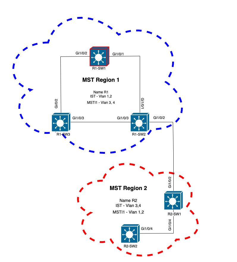
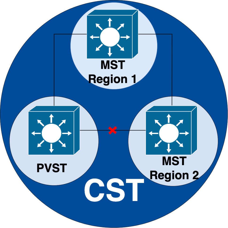
目标是使MST区域像虚拟CST网桥一样运行,从区域外部的角度。
在其他区域或PVST域中的其他交换机,将MST区域视为只有一个交换机,因为RootID和根路径开销保持不变。
MST(单区域)
拓扑

配置
必须在MST区域下的所有交换机上以相同方式配置这三个属性,才能正确收敛。命令在MST配置模式下应用。
- 名称
- 修订版号
- VLAN到实例的映射
spanning-tree mst configuration
name <region name>
revision <number>
instance <number> vlan <vlan number>
使用以下命令验证属性配置:
show running-config | section span
示例:区域1中交换机1、2和3的属性配置
R1-SW1
R1-SW1#show running-config | section spann
spanning-tree mode mst
spanning-tree extend system-id
spanning-tree mst configuration
 name R1               <---
 revision 1            <---
 instance 1 vlan 3-4   <---
R1-SW2
R1-SW2#show running-config | section spann
spanning-tree mode mst
spanning-tree extend system-id
spanning-tree mst configuration
 name R1
 revision 1
 instance 1 vlan 3-4
R1-SW3
R1-SW3#show running-config | section spann
spanning-tree mode mst
spanning-tree extend system-id
spanning-tree mst configuration
 name R1
 revision 1
 instance 1 vlan 3-4
验证
在MST迁移期间,无需更改STP模式即可配置MST参数。
请遵循以下建议,以避免由于配置错误而导致网络中断。
- 提交前检查MST配置。
- 提交后检查MST配置
提交前检查MST配置。
此检查是在尚未应用生成树模式mst时进行的。
show spanning-tree mst
show current
show spanning-tree mst configuration digest
注意:show current仅在MST配置模式(生成树mst配置子模式)下可用
示例:对于区域1中的交换机1
验证STP模式是否尚未处于MST模式
R1-SW1#show spanning-tree mst
% Switch is not in mst mode   <--
验证当前MST配置
R1-SW1(config-mst)#show current
Current MST configuration
Name      [R1]
Revision  1     Instances configured 2

Instance  Vlans mapped
--------  ---------------------------------------------------------------------
0         1-2,6-4094
1         3-4
-------------------------------------------------------------------------------
注意:show current仅在MST配置模式下可用。
注意:show span mst configuration和show current是等效的命令。
验证摘要散列
R1-SW1#show spanning-tree mst configuration digest
% Switch is not in mst mode                          <--
Name [R1]
Revision 1 Instances configured 2
Digest 0xA423B8DBB209CCF6560F55618AB58726            <--
Pre-std Digest 0x8C9BE88BBC9B84CB8AED635EE008436A
注意:摘要输出可让您知道交换机是否已经处于MST模式。摘要散列不会更改,即使尚未启用MST模式。
注意:Catalyst 9000交换机运行IEEE标准MST协议。因此,您必须重点关注Digest散列,而不是Pre-std Digest
提交后检查MST配置
show current
show pending
show spanning-tree mst configuration digest
abort
注:show pending(以及show current)仅在MST配置模式下可用
show current输出显示退出MST子模式(即应用配置更改时)后的MST配置,而show pending输出显示最近配置但未应用的MST配置。
如果出于任何原因需要恢复配置更改,并且您仍处于MST子模式下,则可以应用abort命令,该命令会从MST子模式退出,而不应用更改。
注:show pending(以及show current)仅在MST配置模式下可用
示例:对于区域1中的交换机1
请注意,当前配置和待定配置相同,这意味着未进行任何更改。
摘要散列与上一个输出中验证的散列相同。
R1-SW1(config)#spanning-tree mst configuration
R1-SW1(config-mst)#show current
Current MST configuration
Name      [R1]
Revision  1     Instances configured 2

Instance  Vlans mapped
--------  ---------------------------------------------------------------------
0         1-2,5-4094
1         3-4
-------------------------------------------------------------------------------

R1-SW1(config-mst)#show pending
Pending MST configuration
Name      [R1]
Revision  1     Instances configured 2

Instance  Vlans mapped
--------  ---------------------------------------------------------------------
0         1-2,5-4094
1         3-4
-------------------------------------------------------------------------------

R1-SW1(config-mst)#do show spanning-tree mst configuration digest
Name      [R1]
Revision  1     Instances configured 2
Digest          0xA423B8DBB209CCF6560F55618AB58726   <--
Pre-std Digest  0x8C9BE88BBC9B84CB8AED635EE008436A
将创建新的实例,并将VLAN 5映射到它。这次show current输出不会显示最近配置的新实例,但会显示show pending。这是预期结果。
请注意,摘要散列值未更改。这是因为新配置仅在退出MST配置模式(spanning-tree mst configuration submode)时才适用
 R1-SW1(config-mst)#instance 2 vlan 5       <--
R1-SW1(config-mst)#show current
Current MST configuration
Name      [R1]
Revision  1     Instances configured 2

Instance  Vlans mapped
--------  ---------------------------------------------------------------------
0         1-2,5-4094
1         3-4
-------------------------------------------------------------------------------

R1-SW1(config-mst)#show pending
Pending MST configuration
Name      [R1]
Revision  1     Instances configured 3

Instance  Vlans mapped
--------  ---------------------------------------------------------------------
0         1-2,6-4094
1         3-4
2         5     <--
-------------------------------------------------------------------------------

R1-SW1(config-mst)#do show spanning-tree mst configuration digest
Name      [R1]
Revision  1     Instances configured 2
Digest          0xA423B8DBB209CCF6560F55618AB58726     <--
Pre-std Digest  0x8C9BE88BBC9B84CB8AED635EE008436A
退出MST配置模式后,将反映更改。还会重新计算摘要散列,以便与所做的新更改匹配。
R1-SW1(config-mst)#exit
R1-SW1(config)#spanning-tree mst configuration
R1-SW1(config-mst)#show current
Current MST configuration
Name      [R1]
Revision  1     Instances configured 3

Instance  Vlans mapped
--------  ---------------------------------------------------------------------
0         1-2,6-4094
1         3-4
2         5       <--
-------------------------------------------------------------------------------

R1-SW1(config-mst)#show pending
Pending MST configuration
Name      [R1]
Revision  1     Instances configured 3

Instance  Vlans mapped
--------  ---------------------------------------------------------------------
0         1-2,6-4094
1         3-4
2         5     <--
-------------------------------------------------------------------------------


R1-SW1(config-mst)#do show spanning-tree mst configuration digest
Name      [R1]
Revision  1     Instances configured 3
Digest          0x083305551908B9A2CC50B482DC577B8F     <--
Pre-std Digest  0xA8AC09BDF2942058FAF4CE727C9D258F
这些命令有助于验证MST参数和收敛性。它们还提供与MST计时器、成本等相关的信息。
show spanning-tree pathcost method
show spanning-tree root
show spanning-tree summary
show spanning-tree mst
show spanning-tree interface <interface>
注:show spanning-tree mst和show spanning-tree是等效的
示例:对于区域1中的交换机1
测量路径开销的方法有两种:短(传统)和长。始终最好是沿第2层网络保持同构状态。如果运行长路径开销方法,请沿所有在STP上运行的交换机执行。
R1-SW1#show spanning-tree pathcost method
Spanning tree default pathcost method used is long  <--
此输出现在允许您使用路径开销方法,但也让您知道交换机运行标准MST协议并使用扩展系统ID(使用MST时这是必需的)。
R1-SW1#show spanning-tree summary
Switch is in mst mode (IEEE Standard)               <--
Root bridge for: none
EtherChannel misconfig guard            is enabled
Extended system ID                      is enabled  <--
Portfast Default                        is disabled
PortFast BPDU Guard Default            is disabled
Portfast BPDU Filter Default           is disabled
Loopguard Default                      is disabled
UplinkFast                              is disabled
BackboneFast                            is disabled
Configured Pathcost method used is long             <--

Name                   Blocking Listening Learning Forwarding STP Active
---------------------- -------- --------- -------- ---------- ----------
MST0                         0         0        0          3          3
MST1                         0         0        0          3          3
---------------------- -------- --------- -------- ---------- ----------
2 msts                       0         0        0          6          6
在此输出中可以看到网桥和根ID、优先级、开销、端口角色和状态以及VLAN映射:
R1-SW1#show spanning-tree mst

##### MST0    vlans mapped:   1-2,5-4094
Bridge        address 3473.2db8.be80  priority      32768 (32768 sysid 0)
Root          address f04a.021e.9500  priority      24576 (24576 sysid 0)
              port    Gi1/0/2         path cost     0
Regional Root address f04a.021e.9500  priority      24576 (24576 sysid 0)
                                      internal cost 20000     rem hops 19
Operational   hello time 2 , forward delay 15, max age 20, txholdcount 6
Configured    hello time 2 , forward delay 15, max age 20, max hops    20

Interface                        Role Sts Cost      Prio.Nbr Type
----------------                 ---- --- --------- -------- --------------------------------
Gi1/0/1                          Desg FWD 20000     128.1    P2p
Gi1/0/2                          Root FWD 20000     128.2    P2p
Gi1/0/4                          Desg FWD 20000     128.4    P2p

##### MST1    vlans mapped:   3-4
Bridge        address 3473.2db8.be80  priority      32769 (32768 sysid 1)
Root          address f04a.021e.9500  priority      24577 (24576 sysid 1)
              port    Gi1/0/2         cost          20000     rem hops 19

Interface                        Role Sts Cost      Prio.Nbr Type
----------------                 ---- --- --------- -------- --------------------------------
Gi1/0/1                          Desg FWD 20000     128.1    P2p
Gi1/0/2                          Root FWD 20000     128.2    P2p
Gi1/0/4                          Desg FWD 20000     128.4    P2p
此命令从接口角度(而不是从每个实例的角度)显示STP角色状态、优先级和链路类型。
R1-SW1#show spanning-tree interface gigabitEthernet 1/0/1

Mst Instance        Role Sts Cost      Prio.Nbr Type
------------------- ---- --- --------- -------- --------------------------------
MST0                Desg FWD 20000     128.1    P2p
MST1                Desg FWD 20000     128.1    P2p

R1-SW1#show spanning-tree interface gigabitEthernet 1/0/2

Mst Instance        Role Sts Cost      Prio.Nbr Type
------------------- ---- --- --------- -------- --------------------------------
MST0                Root FWD 20000     128.2    P2p
MST1                Root FWD 20000     128.2    P2p
区域之间的同步
区域2已添加到拓扑中。目的是检查两个不同区域如何交互和收敛的过程。只有边界交换机才会发生在此通信中。
因为链路两端具有相同的通信过程。本部分重点介绍show spanning-tree mst of R1-SW2和从数据包捕获获得的两个BPDU的输出。
拓扑

验证
这是来自区域1的R1-SW2与来自区域2的R2-SW1之间的初始通信。一旦两台设备之间建立连接,它们就会发送BPDU。
重点关注R2-SW1的接口Gi1/0/2,该接口处于阻塞(BLK)初始状态。请记住,交换机端口在选举过程中进入BLK状态。
R2-SW1#show spanning-tree mst

MST0
! Output omitted for brevity

Interface           Role Sts Cost      Prio.Nbr Type
------------------- ---- --- --------- -------- --------------------------------
Gi1/0/2             Desg BLK 20000     128.2    P2p
Gi1/0/4             Root FWD 20000     128.4    P2p

MST1
! Output omitted for brevity

Interface           Role Sts Cost      Prio.Nbr Type
------------------- ---- --- --------- -------- --------------------------------
Gi1/0/2             Desg BLK 20000     128.2    P2p
Gi1/0/4             Root FWD 20000     128.4    P2p
在数据包捕获中,我们观察到第一个BPDU,其中端口角色标志显示为Designated(指定)和Proposal(建议)。
这意味着通信已经启动,并且两个端口都启动了同步过程,以建立协议并设置端口角色和状态。所有这一切都从建议机制开始。
IEEE 802.3 Ethernet
    Destination: Spanning-tree-(for-bridges)_00 (01:80:c2:00:00:00)
    Source: Cisco_05:d6:02 (f0:4a:02:05:d6:02)
    Length: 121
Logical-Link Control
Spanning Tree Protocol
    Protocol Identifier: Spanning Tree Protocol (0x0000)
    Protocol Version Identifier: Multiple Spanning Tree (3)
    BPDU Type: Rapid/Multiple Spanning Tree (0x02)
    BPDU flags: 0x0e, Port Role: Designated, Proposal
        0... .... = Topology Change Acknowledgment: No
        .0.. .... = Agreement: No
        ..0. .... = Forwarding: No
        ...0 .... = Learning: No
        .... 11.. = Port Role: Designated (3)
        .... ..1. = Proposal: Yes
        .... ...0 = Topology Change: No
    Root Identifier: 24576 / 0 / f0:4a:02:1e:95:00
    Root Path Cost: 20004
    Bridge Identifier: 32768 / 0 / a0:f8:49:10:47:80
    Port identifier: 0x8002
    Message Age: 2
    Max Age: 20
    Hello Time: 2
    Forward Delay: 15
    Version 1 Length: 0
    Version 3 Length: 80
    MST Extension
交换机之间交换BPDU后,状态变为学习(LRN)。
在R2-SW1收到之前显示的第一个BPDU之后,LRN状态是阻塞状态之后的第一个过渡状态。
R2-SW1#show spanning-tree mst

MST0
! Output omitted for brevity

Interface           Role Sts Cost      Prio.Nbr Type
------------------- ---- --- --------- -------- --------------------------------
Gi1/0/2             Desg LRN 20000     128.2    P2p
Gi1/0/4             Root FWD 20000     128.4    P2p

MST1
! Output omitted for brevity

Interface           Role Sts Cost      Prio.Nbr Type
------------------- ---- --- --------- -------- --------------------------------
Gi1/0/2             Desg LRN 20000     128.2    P2p
Gi1/0/4             Root FWD 20000     128.4    P2p
一旦某个对等体建立协议并进行同步(接受该邻居作为通向根的上级路径),链路会立即转换到转发状态。
在这里,您可以观察带有设置为学习的标志的BPDU,它还包括拓扑更改通知标志,该标志在端口从LRN转换到转发(FWR)时触发。
在此状态下,MST确定端口是否参与帧转发(状态BLK)。
IEEE 802.3 Ethernet
Logical-Link Control
Spanning Tree Protocol
    Protocol Identifier: Spanning Tree Protocol (0x0000)
    Protocol Version Identifier: Multiple Spanning Tree (3)
    BPDU Type: Rapid/Multiple Spanning Tree (0x02)
    BPDU flags: 0x3d, Forwarding, Learning, Port Role: Designated, Topology Change
        0... .... = Topology Change Acknowledgment: No
        .0.. .... = Agreement: No
        ..1. .... = Forwarding: Yes
        ...1 .... = Learning: Yes
        .... 11.. = Port Role: Designated (3)
        .... ..0. = Proposal: No
        .... ...1 = Topology Change: Yes
    Root Identifier: 24576 / 0 / f0:4a:02:1e:95:00
    Root Path Cost: 20004
    Bridge Identifier: 32768 / 0 / a0:f8:49:10:47:80
    Port identifier: 0x8002
    Message Age: 2
    Max Age: 20
    Hello Time: 2
    Forward Delay: 15
    Version 1 Length: 0
    Version 3 Length: 80
    MST Extension
最后,交换机端口在经过创建网络拓扑时涉及的所有状态后进入转发状态。
这是端口的最后一个状态,角色指定(Desg)且状态为FDW。
R2-SW1#show spanning-tree mst

MST0
! Output omitted for brevity

Interface           Role Sts Cost      Prio.Nbr Type
------------------- ---- --- --------- -------- --------------------------------
Gi1/0/2             Desg FWD 20000     128.2    P2p
Gi1/0/4             Root FWD 20000     128.4    P2p


MST1
! Output omitted for brevity

Interface           Role Sts Cost      Prio.Nbr Type
------------------- ---- --- --------- -------- --------------------------------
Gi1/0/2             Desg FWD 20000     128.2    P2p
Gi1/0/4             Root FWD 20000     128.4    P2p
调试
在R2-SW1和R1-SW2之间的通信期间启用了这些Bug。
debug spanning-tree mstp roles
debug spanning-tree mstp tc
debug spanning-tree mstp boundary
示例:
R2-SW1#show debugging
Packet Infra debugs:

Ip Address                                               Port
------------------------------------------------------|----------

Multiple Spanning Tree:
  MSTP port ROLES changes debugging is on
  MSTP Topology Change notifications debugging is on
  MSTP port BOUNDARY flag changes debugging is on
观察到的日志
%LINK-3-UPDOWN: Interface GigabitEthernet1/0/2, changed state to down
%LINK-3-UPDOWN: Interface GigabitEthernet1/0/2, changed state to up
MST[0]: Gi1/0/2 is now designated port
MST[0]: Gi1/0/2 becomes designated - clearing BOUNDARY flag
MST[1]: Gi1/0/2 is now designated port
MST[0]: port Gi1/0/2 received external tc
MST[0]: port Gi1/0/2 received external tc
MST[1]: port Gi1/0/2 received tc
MST[0]: port Gi1/0/2 received external tc
MST[0]: port Gi1/0/2 received external tc
MST[1]: port Gi1/0/2 received tc
MST[0]: port Gi1/0/2 received external tc
MST[0]: port Gi1/0/2 received external tc
MST[1]: port Gi1/0/2 received tc
MST[0]: port Gi1/0/2 initiating tc
MST[1]: port Gi1/0/2 initiating tc
MST[0]: port Gi1/0/2 received external tc
MST[0]: port Gi1/0/2 received external tc
MST[1]: port Gi1/0/2 received tcsho span
%LINEPROTO-5-UPDOWN: Line protocol on Interface GigabitEthernet1/0/2, changed state to up
MST[0]: port Gi1/0/3 received internal tc
MST[0]: port Gi1/0/3 received internal tc
MST[0]: port Gi1/0/3 received internal tc
PVST模拟故障
PVST模拟是MST用于与非MST交换机通信的机制。
PVST交换机无法识别MST BPDU,因为它们完全不同。这就是理解PVST和MST BPDU之间的差异至关重要的原因。
PVST BPDU与MST BPDU
捕获了两个BPDU,一个用于PVST,另一个用于MST,查看它们之间的差异。
PVST
- PVST为交换机上配置的每个VLAN发送BPDU。因此,配置了100个VLAN意味着100个BPDU在所有端口上发送,以构建自己的无环路拓扑。
- PVST基于传统STP
Ethernet II, Src: Cisco_06:19:01 (f0:4a:02:06:19:01), Dst: PVST+ (01:00:0c:cc:cc:cd)
    Destination: PVST+ (01:00:0c:cc:cc:cd)
    Source: Cisco_06:19:01 (f0:4a:02:06:19:01)
    Type: 802.1Q Virtual LAN (0x8100)
802.1Q Virtual LAN, PRI: 7, DEI: 0, ID: 3
    111. .... .... .... = Priority: Network Control (7)
    ...0 .... .... .... = DEI: Ineligible
    .... 0000 0000 0011 = ID: 3
    Length: 50
Logical-Link Control
    DSAP: SNAP (0xaa)
    SSAP: SNAP (0xaa)
    Control field: U, func=UI (0x03)
    Organization Code: 00:00:0c (Cisco Systems, Inc)
    PID: PVSTP+ (0x010b)
Spanning Tree Protocol
    Protocol Identifier: Spanning Tree Protocol (0x0000)
    Protocol Version Identifier: Spanning Tree (0)
    BPDU Type: Configuration (0x00)
    BPDU flags: 0x01, Topology Change
        0... .... = Topology Change Acknowledgment: No
        .... ...1 = Topology Change: Yes
    Root Identifier: 32768 / 0 / 68:9e:0b:a0:f5:80
        Root Bridge Priority: 32768
        Root Bridge System ID Extension: 0
        Root Bridge System ID: Cisco_a0:f5:80 (68:9e:0b:a0:f5:80)
    Root Path Cost: 20000
    Bridge Identifier: 32768 / 0 / f0:4a:02:06:19:00
        Bridge Priority: 32768
        Bridge System ID Extension: 0
        Bridge System ID: Cisco_06:19:00 (f0:4a:02:06:19:00)
    Port identifier: 0x8001
    Message Age: 1
    Max Age: 20
    Hello Time: 2
    Forward Delay: 15
    Originating VLAN (PVID): 3
        Type: Originating VLAN (0x0000)
        Length: 2
        Originating VLAN: 3
MST
- MST为交换机上配置的所有MST实例发送一个BPDU。这得益于MST扩展(M记录),它包含所有实例的信息。
- MST基于RSTP,这意味着此协议的所有固有机制都继承到MST。
- 计时器由IST定义,并影响区域内的所有其他实例
IEEE 802.3 Ethernet
    Destination: Spanning-tree-(for-bridges)_00 (01:80:c2:00:00:00)
    Source: Cisco_b8:be:81 (34:73:2d:b8:be:81)
    Length: 121
Logical-Link Control
    DSAP: Spanning Tree BPDU (0x42)
    SSAP: Spanning Tree BPDU (0x42)
    Control field: U, func=UI (0x03)
Spanning Tree Protocol
    Protocol Identifier: Spanning Tree Protocol (0x0000)
    Protocol Version Identifier: Multiple Spanning Tree (3)
    BPDU Type: Rapid/Multiple Spanning Tree (0x02)
    BPDU flags: 0x0e, Port Role: Designated, Proposal
        0... .... = Topology Change Acknowledgment: No
        .0.. .... = Agreement: No
        ..0. .... = Forwarding: No
        ...0 .... = Learning: No
        .... 11.. = Port Role: Designated (3)
        .... ..1. = Proposal: Yes
        .... ...0 = Topology Change: No
    Root Identifier: 32768 / 0 / 34:73:2d:b8:be:80
        Root Bridge Priority: 32768
        Root Bridge System ID Extension: 0
        Root Bridge System ID: Cisco_b8:be:80 (34:73:2d:b8:be:80)
    Root Path Cost: 0
    Bridge Identifier: 32768 / 0 / 34:73:2d:b8:be:80
        Bridge Priority: 32768
        Bridge System ID Extension: 0
        Bridge System ID: Cisco_b8:be:80 (34:73:2d:b8:be:80)
    Port identifier: 0x8001
    Message Age: 0
    Max Age: 20
    Hello Time: 2
    Forward Delay: 15
    Version 1 Length: 0
    Version 3 Length: 80
    MST Extension
        MST Config ID format selector: 0
        MST Config name: R1
        MST Config revision: 1
        MST Config digest: a423b8dbb209ccf6560f55618ab58726
        CIST Internal Root Path Cost: 0
        CIST Bridge Identifier: 32768 / 0 / 34:73:2d:b8:be:80
            CIST Bridge Priority: 32768
            CIST Bridge Identifier System ID Extension: 0
            CIST Bridge Identifier System ID: Cisco_b8:be:80 (34:73:2d:b8:be:80)
        CIST Remaining hops: 20
        MSTID 1, Regional Root Identifier 32768 / 34:73:2d:b8:be:80
            MSTI flags: 0x0e, Port Role: Designated, Proposal
                0... .... = Topology Change Acknowledgment: No
                .0.. .... = Agreement: No
                ..0. .... = Forwarding: No
                ...0 .... = Learning: No
                .... 11.. = Port Role: Designated (3)
                .... ..1. = Proposal: Yes
                .... ...0 = Topology Change: No
            1000 .... = Priority: 0x8
            .... 0000 0000 0001 = MSTID: 1
            Regional Root: Cisco_b8:be:80 (34:73:2d:b8:be:80)
            Internal root path cost: 0
            Bridge Identifier Priority: 8
            Port identifier priority: 8
            Remaining hops: 20
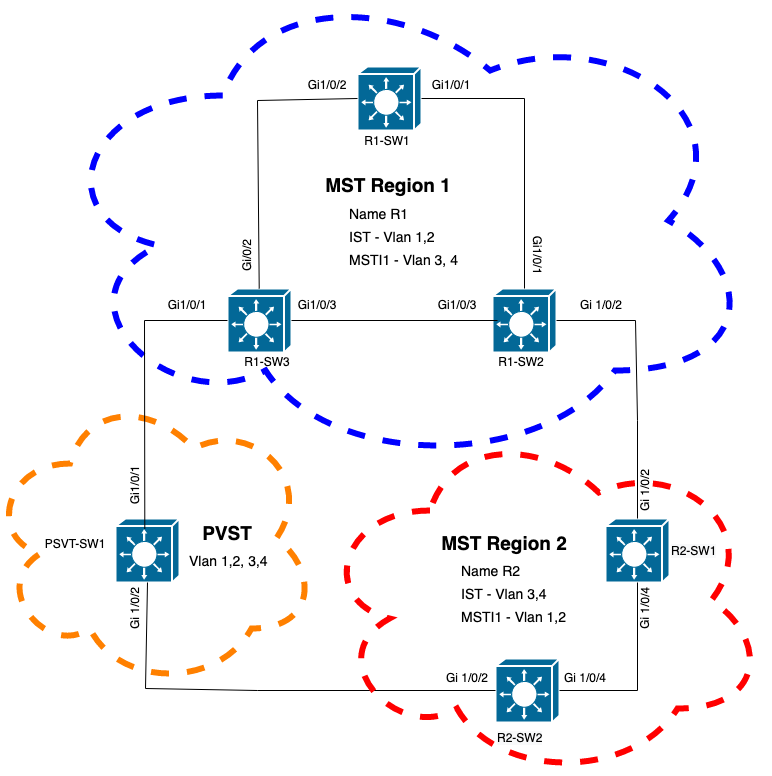
拓扑
已将带有PVST的交换机添加到网络中。它将区域1和区域2互连。

验证
连接PVST交换机后,来自区域1的交换机R1-SW3的边界端口(gi1/0/1)进入PVST不一致并阻塞端口。
R1-SW3#show spanning-tree mst

##### MST0    vlans mapped:   1-2,5-4094
Bridge        address f04a.021e.9500  priority      32768 (32768 sysid 0)
Root          address 689e.0ba0.f580  priority      16385 (16384 sysid 1)
              port    Gi1/0/1         path cost     20000
Regional Root this switch
Operational   hello time 2 , forward delay 15, max age 20, txholdcount 6
Configured    hello time 2 , forward delay 15, max age 20, max hops    20

Interface                        Role Sts Cost      Prio.Nbr Type
----------------                 ---- --- --------- -------- --------------------------------
Gi1/0/1                          Root BKN*20000     128.1    P2p Bound(PVST) *PVST_Inc
Gi1/0/2                          Desg FWD 20000     128.2    P2p
Gi1/0/3                          Desg FWD 20000     128.3    P2p

##### MST1    vlans mapped:   3-4
Bridge        address f04a.021e.9500  priority      32769 (32768 sysid 1)
Root          address 3473.2db8.be80  priority      32769 (32768 sysid 1)
              port    Gi1/0/2         cost          20000     rem hops 19

Interface                        Role Sts Cost      Prio.Nbr Type
----------------                 ---- --- --------- -------- --------------------------------
Gi1/0/1                          Mstr BKN*20000     128.1    P2p Bound(PVST) *PVST_Inc
Gi1/0/2                          Root FWD 20000     128.2    P2p
Gi1/0/3                          Altn BLK 20000     128.3    P2p
注意:在R2-SW2上观察到来自区域2(另一个边界端口)的类似输出。
.
之所以发生这种情况,是因为这些规则都违反了
- 如果CIST的根网桥在非MST区域内,那么该域内VLAN 2的生成树优先级必须比VLAN 1更高(更低)。
- 如果CIST的根网桥在MST区域内,则非MST域中定义的VLAN 2的生成树优先级必须比CIST根更差(更大)。
请查看在交换机上设置的无效配置以解决此问题:
例 1.PVST交换机是VLAN 2-4的根,但VLAN 2-4的优先级比VLAN 1更差(更高)。在这种情况下,除PVST交换机之外的所有交换机都具有默认STP优先级(32768)
PVST-SW1# show run | inc span
spanning-tree mode pvst
spanning-tree extend system-id
spanning-tree vlan 1 priority 4096    <--
spanning-tree vlan 2-4 priority 16384 <--
spanning-tree mst configuration
观察到的日志:
%SPANTREE-2-PVSTSIM_FAIL: Blocking root port Gi1/0/1: Inconsitent inferior PVST BPDU received on VLAN 2, claiming root 16386:689e.0ba0.f580
案例 2.PVST交换机不是VLAN 1的根,但VLAN 2-4的优先级比根高(更低)。在本例中,root拥有默认优先级24576。这意味着根网桥不是所有VLAN的根
PVST-SW1#show run | inc span
spanning-tree mode pvst
spanning-tree extend system-id
spanning-tree vlan 1 prio 32768       <-- higher priority than the root
spanning-tree vlan 2-4 priority 16384 <--  lower priority than the root
spanning-tree mst configuration
观察到的日志:
%SPANTREE-2-PVSTSIM_FAIL: Blocking root port Gi1/0/1: Inconsistent inferior PVST BPDU received on VLAN 2, claiming root 40962:689e.0ba0.f580
考虑上述规则后,可以使用这些有效配置来删除此问题。
例 1.
PVST-SW1# show run | inc span
spanning-tree mode pvst
spanning-tree extend system-id
spanning-tree vlan 1 priority 16384  <-- VLAN 1 has a higher priority than all other VLANs
spanning-tree vlan 2-4 priority 4096 <--
spanning-tree mst configuration
观察到的日志:
%SPANTREE-2-PVSTSIM_OK: PVST Simulation nconsistency cleared on port GigabitEthernet1/0/1.
案例 2.
PVST-SW1#show run | inc span
spanning-tree mode pvst
spanning-tree extend system-id
spanning-tree vlan 1 prio 32768       <-- higher priority than the root
spanning-tree vlan 2-4 priority 40960 <--  higher priority than the root
spanning-tree mst configuration
观察到的日志:
%SPANTREE-2-PVSTSIM_OK: PVST Simulation nconsistency cleared on port GigabitEthernet1/0/1.
调试
如果无法捕获数据包,请使用BPDU调试检验BPDU。
debug spanning-tree mstp bpdu receive
debug spanning-tree mstp bpdu transmit
示例:对于区域2中连接到PVST交换机的交换机2
R2-SW2#debug spanning-tree mstp bpdu receive
MSTP BPDUs RECEIVEd dump debugging is on
R2-SW2#debug spanning-tree mstp bpdu transmit
MSTP BPDUs TRANSMITted dump debugging is on
R2-SW2#debug condition interface gigabitEthernet 1/0/2 <-- interface facing PVST switch

R2-SW2#show logging
! Output omitted for brevity
%LINK-3-UPDOWN: Interface GigabitEthernet1/0/2, changed state to down
%LINK-3-UPDOWN: Interface GigabitEthernet1/0/2, changed state to up
MST[0]:-TX> Gi1/0/2 BPDU Prot:0 Vers:3 Type:2
MST[0]: Role :Desg Flags[P] Age:2 RemHops:19
MST[0]: CIST_root:16385.689e.0ba0.f580 Cost :40000
MST[0]: Reg_root :32768.f04a.0205.d600 Cost :20000
MST[0]: Bridge_ID:32768.a0f8.4910.4780 Port_ID:32770
MST[0]: max_age:20 hello:2 fwdelay:15
MST[0]: V3_len:80 region:R2 rev:1 Num_mrec: 1
MST[1]:-TX> Gi1/0/2 MREC
MST[1]: Role :Desg Flags[MAP] RemHops:20
MST[1]: Root_ID :32769.a0f8.4910.4780 Cost :0
MST[1]: Bridge_ID:32769.a0f8.4910.4780 Port_id:130
%LINEPROTO-5-UPDOWN: Line protocol on Interface GigabitEthernet1/0/2, changed state to up
MST[0]:-TX> Gi1/0/2 BPDU Prot:0 Vers:3 Type:2
MST[0]: Role :Desg Flags[P] Age:2 RemHops:19
MST[0]: CIST_root:16385.689e.0ba0.f580 Cost :40000
MST[0]: Reg_root :32768.f04a.0205.d600 Cost :20000
MST[0]: Bridge_ID:32768.a0f8.4910.4780 Port_ID:32770
MST[0]: max_age:20 hello:2 fwdelay:15
MST[0]: V3_len:80 region:R2 rev:1 Num_mrec: 1
MST[1]:-TX> Gi1/0/2 MREC
MST[1]: Role :Desg Flags[MAP] RemHops:20
MST[1]: Root_ID :32769.a0f8.4910.4780 Cost :0
MST[1]: Bridge_ID:32769.a0f8.4910.4780 Port_id:130
MST[0]:


      MST[0]: Role :Desg Flags[FLTc] Age:0


      MST[0]: CIST_root:16385.689e.0ba0.f580 Cost :0


      MST[0]: Bridge_ID:16385.689e.0ba0.f580 Port_ID:32770


      MST[0]: max_age:20 hello:2 fwdelay:15
P2P争议
拓扑

说明
在本节中,您会发现两台设备无法建立协议并正确设置端口状态的问题。
R1-SW1#show spanning-tree mst

##### MST0    vlans mapped:   1-2,5-4094
Bridge        address 3473.2db8.be80  priority      32768 (32768 sysid 0)
Root          address 689e.0ba0.f580  priority      4097  (4096 sysid 1)
              port    Gi1/0/2         path cost     20000
Regional Root address f04a.021e.9500  priority      24576 (24576 sysid 0)
                                      internal cost 20000     rem hops 19
Operational   hello time 2 , forward delay 15, max age 20, txholdcount 6
Configured    hello time 2 , forward delay 15, max age 20, max hops    20

Interface                        Role Sts Cost      Prio.Nbr Type
----------------                 ---- --- --------- -------- --------------------------------
Gi1/0/1                          Desg FWD 20000     128.1    P2p
Gi1/0/2                          Root FWD 20000     128.2    P2p
Gi1/0/4                          Desg BLK 20000     128.2    P2p Dispute

##### MST1    vlans mapped:   3-4
Bridge        address 3473.2db8.be80  priority      32769 (32768 sysid 1)
Root          address f04a.021e.9500  priority      24577 (24576 sysid 1)
              port    Gi1/0/2         cost          20000     rem hops 19

Interface                        Role Sts Cost      Prio.Nbr Type
----------------                 ---- --- --------- -------- --------------------------------
Gi1/0/1                          Desg FWD 20000     128.1    P2p
Gi1/0/2                          Root FWD 20000     128.2    P2p
Gi1/0/4                          Desg BLK 20000     128.2    P2p Dispute
R1-SW1(根)发现新设备已连接到该交换机。因此它会发送其BPDU并将自身定义为根。
它收到一个BPDU,它指定在链路的另一端,将标志设置为端口角色:指定、转发和学习。
这意味着新交换机连接的状态具有到达根的更好路径。但是,这是不可能的,因为R1-SW1是根,没有更好的路径可达它。
由于两台交换机无法建立协议并正确设置端口(因为两台BPDU都显示了通向根的更好路径),R1-SW1会假设新交换机未收到其BPDU,并将端口状态设置为P2P争议,以避免可能导致环路的单向场景。
MST方法
如本文档所述,只要向网络添加更多交换机,MST就会更加复杂。因此,对同一网络采用不同的方法非常重要。
示例:
如果发现的问题不在MST区域内,而是在PVST域内,则您可以拥有更广阔的视野并忽略MST区域内的任何内容(CST视角)。

另一方面,如果怀疑问题在MST区域之间或区域内部,则CIST可提供更好的视角。

如果需要,您可以将重点放在交换机的端口角色和状态上

相关信息
- 了解多生成树协议 (802.1s)
- 第2层配置指南,Cisco IOS XE Amsterdam 17.3.x(Catalyst 9300交换机)
- 第2层和第3层配置指南,Cisco IOS XE Everest 16.5.1a(Catalyst 9300交换机)
- MST交换机上的PVST模拟
- Cisco Bug ID CSCvy02075 — 交换机转发处于阻塞BLK状态的端口上接收的流量
修订历史记录
| 版本 | 发布日期 | 备注 |
|---|---|---|
1.0 |
26-Oct-2022 |
初始版本 |
 反馈
反馈