将独立Catalyst 6500交换机迁移至Catalyst 6500 VSS
简介
本文档提供有关将独立Cisco Catalyst 6500系列交换机迁移到Cisco Catalyst 6500虚拟交换系统的过程的信息。
注意:本文档提供迁移所需的常见步骤。确切的步骤取决于当前的交换机配置,可能与下述步骤略有不同。
先决条件
要求
Cisco 建议您了解以下主题:
-
虚拟交换系统 (VSS) 概念知识。有关详细信息,请参阅了解虚拟交换系统。
使用的组件
本文档中的信息基于 Cisco Catalyst 6500 系列交换机,其中配有 Supervisor VS-S720-10G-3C/XL 并运行 Cisco IOS® 软件版本 12.2(33)SXH1 或更高版本。
本文档中的信息都是基于特定实验室环境中的设备编写的。如果您使用的是真实网络,请确保您已经了解所有命令的潜在影响。
规则
有关文档规则的详细信息,请参阅 Cisco 技术提示规则。
背景信息
虚拟交换系统 (VSS) 是 Cisco Catalyst 6500 系列交换机的一项新增的创新功能,该功能有效地使两个物理机箱一起群集到单个逻辑实体中。这种技术可以在企业园区和数据中心部署的所有区域实现新的增强功能,包括高可用性、可扩展性/性能、管理和维护。
目前实现 VSS 使您能够将两个物理 Cisco Catalyst 6500 系列交换机一起合并到单个逻辑管理的实体中。下图以图形方式表示在启用 VSS 后将两个 6509 机箱作为单个 18 插槽机箱进行管理这一概念:

迁移进程
硬件和软件支持
VSS 是 Cisco Catalyst 6500 系列交换机独有的软件功能。要启用和配置此项功能,需要具备以下条件:
| Hardware | VS-S720-10G-3C/XL |
| 软件 | Cisco IOS 软件版本 12.2(33)SXH1 或更高版本 |
| 型号 | 描述 |
| WS-C6503-E | E系列3插槽机箱 |
| WS-C6504-E | E系列4插槽机箱 |
| WS-C6506 | 6插槽机箱 |
| WS-C6506-E | E系列6插槽机箱 |
| WS-C6509 | 9插槽机箱 |
| WS-C6509-E | E系列9插槽机箱 |
| WS-C6509-NEB-A | 9插槽垂直网络设备构建标准(NEBS)机箱 |
| WS-C6509-V-E | E系列9插槽垂直机箱 |
| WS-C6513 | 13插槽机箱 |
下表提供了思科虚拟交换系统初始版本支持的机箱的完整列表。有关详细信息,请参阅Cisco Catalyst 6500系列虚拟交换系统(VSS)1440。
迁移路径
下表列出了迁移到 VSS 的一些可能路径。此列表仅用作提示,且并不全面。
| 初始设置 | 所需的升级 | 最终设置 |
|---|---|---|
| 两台带 WS-SUP720-3B Supervisor 的 Cisco Catalyst 6500 系列交换机。 |
硬件升级 — Supervisor VS-S720-10G-3C/XL软件升级 — Cisco IOS 12.2(33)SXH1或更高版本 | VSS |
| 两台带 VS-S720-10G-3C/XL Supervisor 的 Cisco Catalyst 6500 系列交换机。 |
软件升级 - Cisco IOS 12.2(33)SXH1 或更高版本 | VSS |
迁移概述
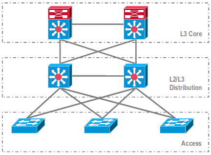
独立环境下的常见配置

在第 3 层 (L3) 核心层与 L2/L3 分布层之间运行的功能或协议:
-
IP 路由协议
-
L3 端口信道或 IP 路由的 EqualCost MultiPath 功能
在 L2/L3 分布层与接入层之间运行的功能或协议:
-
生成树协议
-
第一跳路由协议(FHRP)
-
策略:QoS、ACL
-
L2 中继、VLAN、端口信道
迁移至 VSS
该过程包含多个步骤,本部分将对每个步骤进行说明。

核心层与分布层之间的迁移步骤:
-
配置多机箱EtherChannel(MEC)
-
修改 IP 路由配置并删除不再需要的命令
分布层与接入层之间的迁移步骤:
-
配置 MEC
-
保持生成树协议 (STP) 处于启用状态
-
修改 FHRP 命令
-
将 QoS 和 ACL 策略移至 MEC(如果需要)
-
将 L2 中继配置移至 MEC
逐步迁移过程
请完成以下步骤:
-
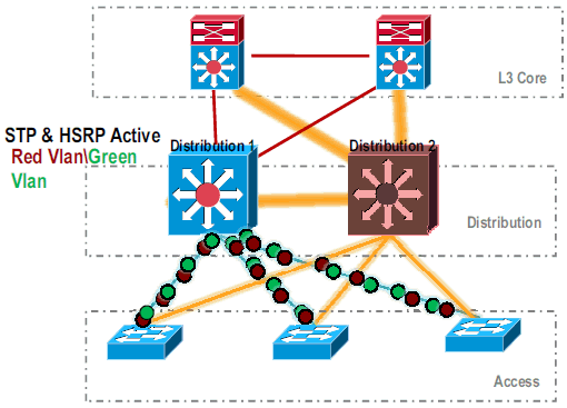
在初始独立设置中,通常使用 VLAN 负载共享和 HSRP 配置对分布层交换机之间的数据流进行负载均衡。

-
修改 HSRP 和 STP 配置,使 Distribution-1 对所有数据流均保持活动状态,同时使相邻设备检测到此更改,并将所有数据流发送给 Distribution-1。

-
关闭 Distribution-2 的物理接口,使其与网络隔离。

。
将 Distribution-2 完全从网络中移除后,可将其转换为 VSS 模式而不影响生产数据流。
-
请安装新的 Supervisor (VS-SUP720-10G)(如果以前未安装),并验证其状态。
Distribution-2#show module
Mod Ports Card Type                              Model              Serial No.
--- ----- -------------------------------------- ------------------ -----------
  5    5  Supervisor Engine 720 10GE (Active)    VS-S720-10G        SAD104707BB
  9   48  CEF 720 48 port 10/100/1000mb Ethernet WS-X6748-GE-TX     SAL1020NGY3
-
将与 VSS 兼容的 Cisco IOS 软件复制到 sup-bootdisk:
Distribution-2#copy ftp: sup-bootdisk:
Address or name of remote host []? 172.16.85.150
Source filename []? s72033-ipservices_wan_vz.122-33.SXH1.bin
Destination filename [s72033-ipservices_wan_vz.122-33.SXH1.bin]?
Accessing ftp://172.16.85.150/s72033-ipservices_wan_vz.122-33.SXH1.bin...
-
更新 bootvar 以加载复制到 sup-bootdisk 中的 Cisco IOS 软件:
Distribution-2(config)#boot system flash sup-bootdisk:s72033-ipservices_wan_vz.122-33.SXH1.bin -
要使Distribution-2交换机在VSS模式下运行,需要虚拟交换机链路(VSL)。可以使用 Distribution-1 与 Distribution-2 之间当前的端口信道链路形成 VSL。

-
配置虚拟交换机属性:
-
虚拟交换机域编号(在网络中唯一)
-
虚拟交换机编号(在域中唯一)
-
虚拟交换机链路 (VSL)
Distribution-2(config)#hostname VSS

VSS(config)#switch virtual domain 100

VSS(config-vs-domain)#switch 1


!--- After conversion Distribution-2 will be noted !--- as Switch 1 in VSS mode.

VSS(config-vs-domain)# exit
VSS(config)#interface port-channel 1
VSS(config-if)#switch virtual link 1

VSS(config-if)#interface TenG 5/4
VSS(config-if)#channel-group 1 mode on
VSS(config-if)#interface TenG 5/5
VSS(config-if)#channel-group 1 mode on
VSS(config-if)# ^Z
VSS#
-
-
将 Distribution-2 交换机转换为 VSS 模式。
注意:通过交换机的控制台发出以下命令:
VSS#switch convert mode virtual

This command will convert all interface
names to naming convention "interface-type
switch-number/slot/port",
save the running config to startup-config and
reload the switch.
Do you want to proceed? [yes/no]: yes
Converting interface names
Building configuration...


!--- At this point the switch will reboot


!--- snippet of the console output

System detected Virtual Switch configuration...
 Interface TenGigabitEthernet 1/5/4 is member of
PortChannel 1
 Interface TenGigabitEthernet 1/5/5 is member of
PortChannel 1

!--- snippet of the console output

00:00:23: %PFREDUN-6-ACTIVE: Initializing as ACTIVE
processor for this switch

!--- snippet of the console output

00:00:28: %VSL_BRINGUP-6-MODULE_UP: VSL module in slot 5
switch 1 brought up
Initializing as Virtual Switch Active
-
验证 Distribution-2 交换机是否已转换至 VSS 模式。
VSS#show switch virtual role

Switch  Switch Status  Preempt    Priority   Role     Session ID
        Number         Oper(Conf) Oper(Conf)          Local  Remote
-------------------------------------------------------------------
LOCAL    1     UP      FALSE(N)    110(110)  ACTIVE    0      0

In dual-active recovery mode: No
Distribution-2 交换机转换成功并在 VSS 模式下运行。对 Distribution-1 交换机进行转换后,还可以执行预配置步骤。预配置有助于减少迁移过程中数据包的丢失量。

-
完成以下步骤,对 VSS Switch-1 进行预配置:
-
使用 Switch-1 的本地接口配置 MEC。将 Switch-2(当前为 Distribution-1)的接口转换到 VSS 模式后,可将其添加到 MEC 中。
-
配置 MEC。
-
将接口配置移至 MEC。
-
将 QoS 和 ACL 策略移至 MEC。
配置更改interface TenGigabitEthernet1/2/1 ip address 192.168.4.2 255.255.255.0 interface GigabitEthernet1/1/2 switchport switchport trunk encapsulation dot1q switchport trunk allowed vlan 10,20
配置相邻设备以支持端口信道!--- MEC to Core layer VSS(config)# int ten 1/2/1 VSS(config-if)# no ip address VSS(config-if)# interface po20 VSS(config-if)# ip address 192.168.4.2 255.255.255.0 VSS(config-if)# no shut VSS(config-if)# interface ten1/2/1 VSS(config-if)# channel-group 20 mode desirable !--- MEC to Access layer VSS(config-if)# interface po10 VSS(config-if)# switchport VSS(config-if)# switchport trunk encapsulation dot1q VSS(config-if)# switchport trunk allowed vlan 10,20 VSS(config-if)# no shut VSS(config-if)# interface gig1/1/2 VSS(config-if)# switchport VSS(config-if)# channel-group 10 mode desirable
VSS Switch-1 与其相邻设备之间的连接目前处于断开状态。因此,对端口信道进行配置并不会影响通过 Distribution-1 的数据流。
!--- In Core layer devices

Core(config)# int gig 1/1
Core(config-if)# no ip address
Core(config-if)# int po20
Core(config-if)# ip address 192.168.4.1 255.255.255.0
Core(config-if)# no shut
Core(config-if)# int gig 1/1
Core(config-if)# channel-group 20 mode desirable
!--- In Access layer devices

Access(config)# int po10
Access(config-if)# switchport
Access(config-if)# switchport trunk encapsulation dot1q
Access(config-if)# switchport trunk
Access(config-if)# no shut
Access(config-if)# int gig 1/1
Access(config-if)# channel-group 10 mode desirable
-
-
在 VSS 中,活动机箱和备用机箱均使用活动机箱固化的 MAC 地址和 VLAN IP 地址。不再需要 HSRP。
-
将 HSRP 虚拟 IP 地址移至 VLAN 接口。
-
从 VLAN 接口删除 HSRP 配置。
配置更改interface Vlan10 ip address 10.1.1.2 255.255.255.0 standby 10 ip 10.1.1.1 standby 10 priority 110 ! interface Vlan20 ip address 20.1.1.2 255.255.255.0 standby 20 ip 20.1.1.1 standby 20 priority 110 !
VSS(config)# interface Vlan10
VSS(config-if)# no standby 10 ip 10.1.1.1
VSS(config-if)# no standby 10 priority 110
VSS(config-if)# ip address 10.1.1.1 255.255.255.0
VSS(config-if)# interface Vlan20
VSS(config-if)# no standby 20 ip 20.1.1.1
VSS(config-if)# no standby 20 priority 110
VSS(config-if)# ip address 20.1.1.1 255.255.255.0
注意:终端设备仍会将其ARP条目指向初始HSRP MAC地址。当这些条目超时或发送其他 ARP 更新设备缓存时,某些连接会断开。
-
-
为所使用的 IP 路由协议启用 NSF-SSO 功能。VSS 可简化路由配置,所以无需再使用某些网络语句。因此,可以删除这些语句。
VSS Switch-1
核心VSS#show running-config | begin ospf router ospf 1 log-adjacency-changes network 10.1.1.0 0.0.0.255 area 0 network 20.1.1.0 0.0.0.255 area 0 network 192.168.4.0 0.0.0.255 area 0 network 192.168.5.0 0.0.0.255 area 0 !--- rest of output elided !--- Previous L3 interfaces are merged as MEC, hence some routing statements are no longer required. VSS(config)# router ospf 1 VSS(config-router)# nsf VSS(config-router)# no network 192.168.5.0 0.0.0.255 area 0
Core#show running-config | begin ospf
router ospf 1
 log-adjacency-changes
 network 192.168.4.0 0.0.0.255 area 0
 network 192.168.5.0 0.0.0.255 area 0

!--- rest of output elided


!--- Previous L3 interfaces are merged as MEC, hence some routing statements are no longer required.


Core(config)# router ospf 1
Core(config-router)# nsf
Core(config-router)# no network 192.168.5.0 0.0.0.255 area 0
-
修改 STP 配置,使 VSS Switch-1 成为所有 VLAN 的根。
-
-
验证 VSS Switch-1 配置和连接。
-
启用 VSS Switch-1 的接口。
-
验证 L2 与接入层设备的连接。
-
验证 L3 与核心层设备的连接。

-
-
验证 VSS Switch-1 的连接后,关闭 Distribution-1 的接口以将数据流交换给 VSS。

-
在 Distribution-1 交换机上重复转换步骤,将交换机切换到首选的 VSS 备用模式。
Distribution-1(config)#hostname VSS

VSS(config)#switch virtual domain 100

VSS(config-vs-domain)#switch 2


!--- After conversion Distribution-1 will be noted !--- as Switch 2 in VSS mode.

VSS(config-vs-domain)# exit
VSS(config)#interface port-channel 2
VSS(config-if)#switch virtual link 2

VSS(config-if)#interface TenG 5/4
VSS(config-if)#channel-group 2 mode on
VSS(config-if)#interface TenG 5/5
VSS(config-if)#channel-group 2 mode on
VSS(config-if)# ^Z
VSS#

VSS#switch convert mode virtual

This command will convert all interface
names to naming convention "interface-type
switch-number/slot/port",
save the running config to startup-config and
reload the switch.
Do you want to proceed? [yes/no]: yes
Converting interface names
Building configuration...


!--- At this point the switch will reboot


!--- snippet of the console output

System detected Virtual Switch configuration...
 Interface TenGigabitEthernet 2/5/4 is member of
PortChannel 2
 Interface TenGigabitEthernet 2/5/5 is member of
PortChannel 2

!--- snippet of the console output

00:00:23: %PFREDUN-6-ACTIVE: Initializing as ACTIVE
processor for this switch

!--- snippet of the console output

00:00:28: %VSL_BRINGUP-6-MODULE_UP: VSL module in slot 5
switch 2 brought up
Initializing as Virtual Switch Standby
-
VSS 备用交换机启动后,VSS 活动配置会自动同步到 VSS 备用交换机上。启动时,VSS 备用交换机 (Switch-2) 的接口处于关闭状态。

-
确定虚拟交换机配置。
注意:此最后的关键步骤仅适用于首次转换。如果已经对交换机进行了转换或部分转换,则不能使用此命令。如果交换机已转换或部分转换,则会生成错误消息:
11:27:30: %PM-SP-4-ERR_DISABLE: channel-misconfig error detected
on Po110, putting Gi9/2 in err-disable state
可以在活动的虚拟交换机上发出以下命令以自动配置备用虚拟交换机:
VSS#switch accept mode virtual

This command will bring in all VSL configurations from the standby
switch and populate it into the running configuration.
In addition the startup configurations will be updated with the
new merged configurations.
Do you want proceed? [yes/no]: yes
Merging the standby VSL configuration. . .
Building configuration...
注意:请注意,在Cisco IOS软件版本12.2 SXI中,交换机接受模式虚拟命令不再需要,因为配置会自动合并。
-
将 Switch-2 的接口添加到 MEC 中。
- VSS
!--- To Core layer

VSS(config)# interface range tengig 1/2/1, tengig2/2/1
VSS(config-if-range)# channel-group 20 mode desirable
VSS(config-if-range)# no shut


!--- To Access layer

VSS(config)# interface range gig 1/1/2, gig 2/1/2
VSS(config-if-range)# switchport
VSS(config-if-range)# channel-group 10 mode desirable
VSS(config-if-range)# no shut
- VSS 邻居 - 核心层
Core(config)# interface range gig 1/1, gig 1/2
Core(config-if-range)# channel-group 20 mode desirable
Core(config-if-range)# no shut
- VSS 邻居 - 接入层
Access(config)# interface range gig 1/1, gig 1/2
Access(config-if-range)# channel-group 10 mode desirable
Access(config-if-range)# no shut
向 VSS 的迁移过程完成。此时,VSS 的两台交换机都在运行,并且数据流在所有上行链路接口上均保持负载均衡。

- VSS
相关信息
修订历史记录
| 版本 | 发布日期 | 备注 |
|---|---|---|
1.0 |
01-Dec-2013 |
初始版本 |


 反馈
反馈