Troubleshoot ACI Fabric Discovery - Multi-Pod Discovery
下載選項
無偏見用語
本產品的文件集力求使用無偏見用語。針對本文件集的目的,無偏見係定義為未根據年齡、身心障礙、性別、種族身分、民族身分、性別傾向、社會經濟地位及交織性表示歧視的用語。由於本產品軟體使用者介面中硬式編碼的語言、根據 RFP 文件使用的語言,或引用第三方產品的語言,因此本文件中可能會出現例外狀況。深入瞭解思科如何使用包容性用語。
關於翻譯
思科可能会在某些地方提供本内容的当地语言翻译版本。请注意,翻译版本仅供参考,如有任何不一致之处,以本内容的英文版本为准。
目錄
簡介
本文檔介紹瞭解ACI多Pod Discovery並對其進行故障排除的步驟。
背景資訊
本文中的資料摘自 思科以應用為中心的基礎設施第二版故障排除 書,特別是Fabric Discovery - 多Pod發現 章節。
多Pod概述
ACI多Pod允許部署單個APIC集群來管理互連的多個ACI網路。這些單獨的ACI網路稱為「Pod」,每個Pod都是常規的兩層或三層主幹 — 枝葉拓撲。單個APIC群集可以管理多個Pod。
多Pod設計還允許跨Pod擴展ACI交換矩陣策略,這些交換機可以實際存在於多個房間中,甚至可以跨遠端資料中心位置。在多Pod設計中,在APIC控制器集群上定義的任何策略將自動可供所有Pod使用。
最後,多Pod設計增強了故障域隔離。事實上,每個Pod運行其自己的COOP、MP-BGP和IS-IS協定的例項,因此這些協定中的任何一個故障和問題都包含在Pod中,不能傳播到其他Pod。
請參閱cisco.com上的「ACI Multi-Pod White Paper(ACI多平台白皮書)」文檔,瞭解有關多平台設計和最佳實踐的詳細資訊。
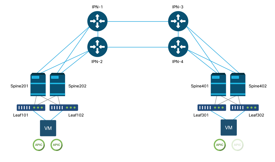
多Pod ACI交換矩陣的主要元素是枝葉和主幹交換機、APIC控制器和IPN裝置。
此示例深入到故障排除工作流程,瞭解與設定ACI多埠交換矩陣有關的問題。本節使用的參考拓撲如下圖所示:
ACI多Pod參考拓撲
故障排除工作流
驗證ACI策略
訪問策略
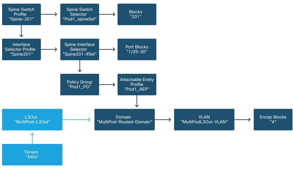
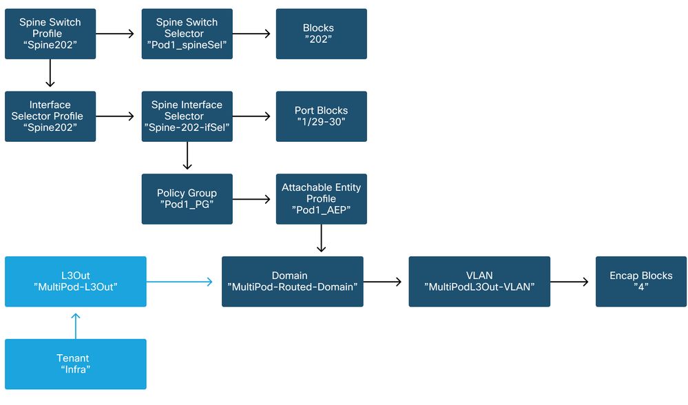
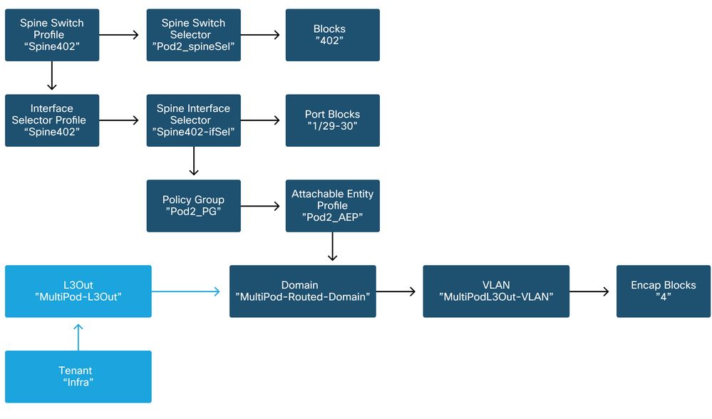
多Pod使用L3Out通過「infra」租戶連線Pod。這意味著需要設定標準訪問策略集,以在面向IPN的主幹埠上啟用所需的多Pod L3Out封裝(VLAN-4)。
可通過「新增Pod」嚮導配置訪問策略,該嚮導應用於部署多Pod。使用嚮導後,可從APIC GUI驗證已部署的策略。如果沒有正確配置策略,則次租戶上會出現故障,並且從主幹到IPN的連線可能未按預期工作。
驗證主幹節點上面向IPN的介面的訪問策略定義時,可以引用以下方案:
骨幹201
骨幹202
骨幹401

骨幹402
在infra租戶中,應根據以下架構配置多面板L3Out:
在基礎架構租戶中的多面板L3Out
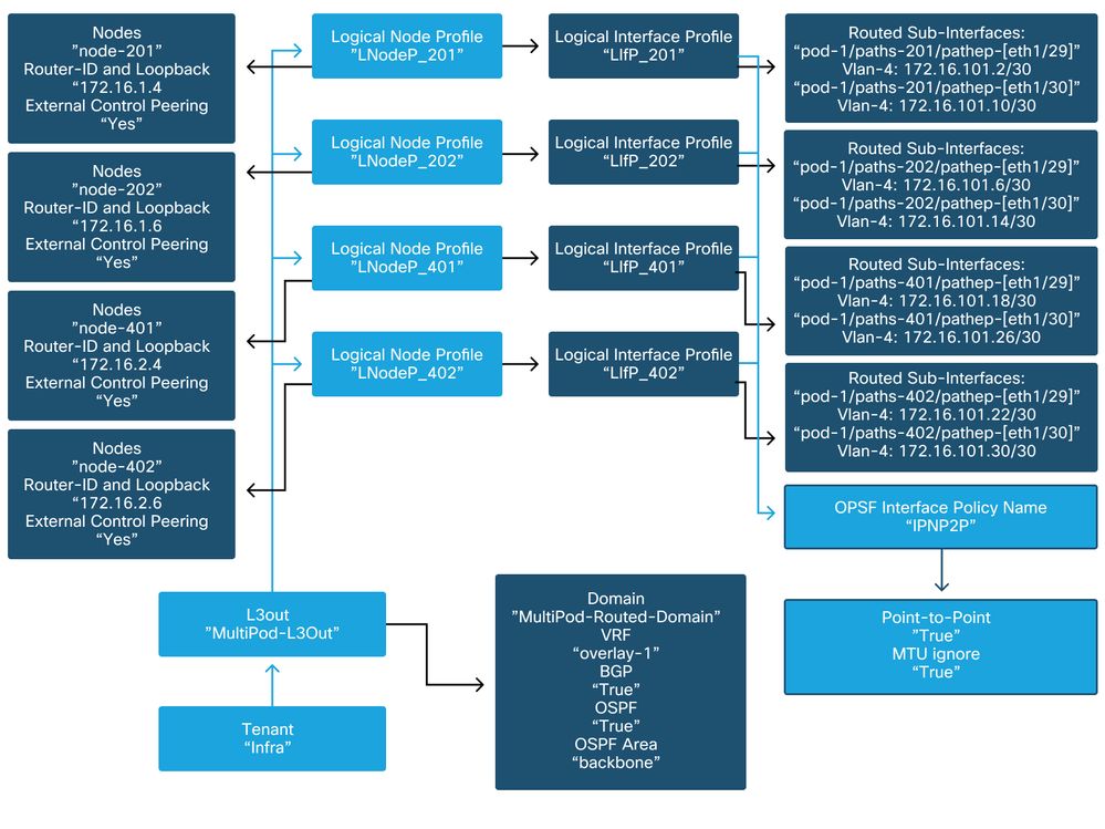
下面是多Pod L3Out邏輯介面配置檔案配置的參考快照。對於主幹201,路由器子介面定義應如下圖所示
基礎設施L3Out中的邏輯介面配置檔案

對於每個Pod,應有一個TEP池,如下圖所示。請注意,APIC控制器將使用TEP池為overlay-1 VRF調配節點的IP地址。
Pod交換矩陣設定策略

交換矩陣外部連線策略預設值
驗證在次租戶中是否定義並正確配置了「Fabric Ext Policy default」對象。此配置的示例如下圖所示。
交換矩陣外部連線策略預設值

資料平面TEP

交換矩陣外部路由配置檔案子網
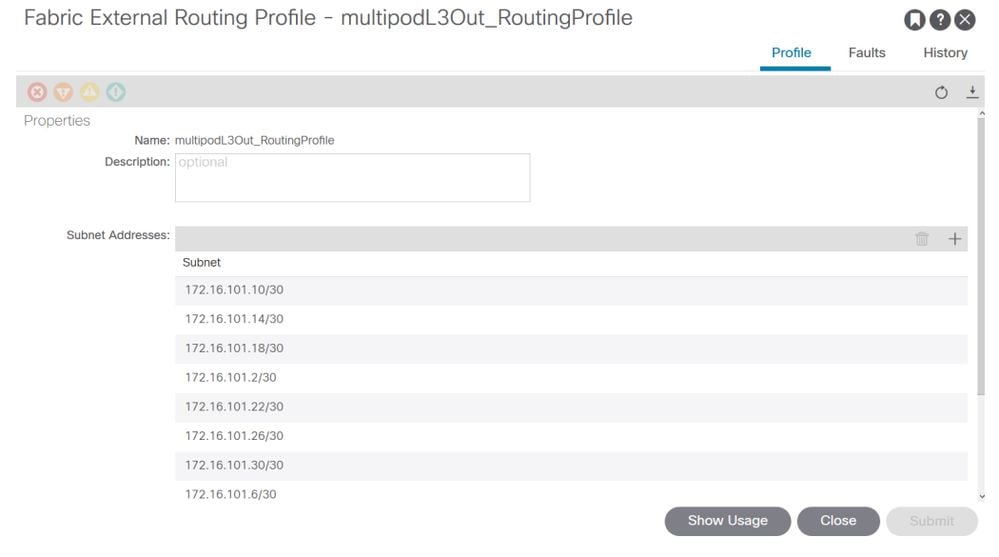
Fabric External Routing Profile使使用者能夠驗證所定義的IPN的所有路由子網是否都位於其上。
IPN驗證
多Pod依賴於Pod間網路(IPN),該網路將提供POD到POD連線。檢驗IPN的配置是否正確就位非常關鍵。通常,配置有故障或缺失是發生故障時意外行為或流量丟棄的來源。本節將詳細介紹IPN的配置。
在下一節中,參考以下IPN拓撲:
IPN拓撲
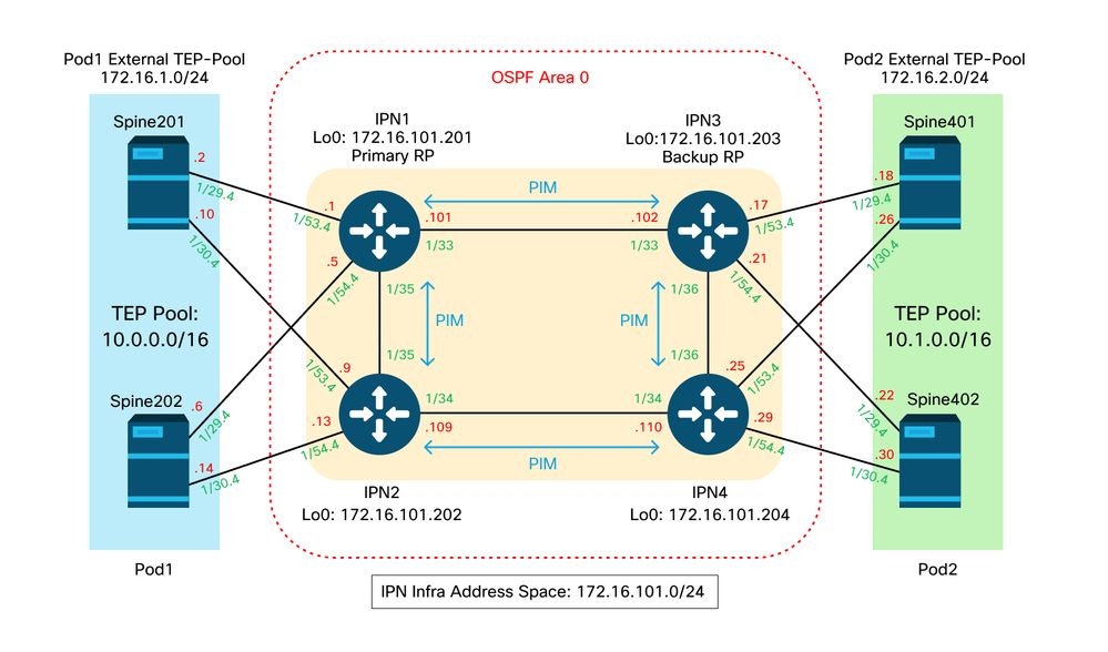
主幹到IPN dot1q VLAN-4子介面連線
通過VLAN-4上的子介面實現了主幹到IPN的點對點連線。此連線的第一個驗證是測試主幹與IPN裝置之間的IP可達性。
為此,請確定正確的介面並驗證其是否顯示為開啟。
S1P1-Spine201# show ip int brief vrf overlay-1 | grep 172.16.101.2
eth1/29.29           172.16.101.2/30      protocol-up/link-up/admin-up

S1P1-Spine201# show ip interface  eth1/29.29
IP Interface Status for VRF "overlay-1"
eth1/29.29, Interface status: protocol-up/link-up/admin-up, iod: 67, mode: external
  IP address: 172.16.101.2, IP subnet: 172.16.101.0/30
  IP broadcast address: 255.255.255.255
  IP primary address route-preference: 0, tag: 0

S1P1-Spine201# show system internal ethpm  info interface Eth1/29.29
Ethernet1/29.29 - if_index: 0x1A01C01D
Router MAC address: 00:22:bd:f8:19:ff
Admin Config Information:
  state(up), mtu(9150), delay(1), vlan(4), cfg-status(valid)
  medium(broadcast)
Operational (Runtime) Information:
  state(up), mtu(9150), Local IOD(0x43), Global IOD(0x43), vrf(enabled)
  reason(None)
  bd_id(29)
Information from SDB Query (IM call)
  admin state(up), runtime state(up), mtu(9150),
  delay(1), bandwidth(40000000), vlan(4), layer(L3),
  medium(broadcast)
  sub-interface(0x1a01c01d) from parent port(0x1a01c000)/Vlan(4)
  Operational Bits:

User config flags:  0x1
  admin_router_mac(1)

Sub-interface FSM state(3)
No errors on sub-interface
Information from GLDB Query:
Router MAC address: 00:22:bd:f8:19:ff
驗證介面已啟動後,現在測試點對點IP連線:
S1P1-Spine201# iping -V overlay-1 172.16.101.1
PING 172.16.101.1 (172.16.101.1) from 172.16.101.2: 56 data bytes
64 bytes from 172.16.101.1: icmp_seq=0 ttl=255 time=0.839 ms
64 bytes from 172.16.101.1: icmp_seq=1 ttl=255 time=0.719 ms
^C
--- 172.16.101.1 ping statistics ---
2 packets transmitted, 2 packets received, 0.00% packet loss
round-trip min/avg/max = 0.719/0.779/0.839 ms
如果存在任何連線問題,請驗證遠端IPN(IPN1)上的佈線和配置。
IPN1# show ip interface brief | grep 172.16.101.1
Eth1/33              172.16.101.101  protocol-up/link-up/admin-up
Eth1/35              172.16.101.105  protocol-up/link-up/admin-up
Eth1/53.4            172.16.101.1    protocol-up/link-up/admin-up

IPN1# show run int Eth1/53.4
interface Ethernet1/53.4
description to spine 1pod1
mtu 9150
encapsulation dot1q 4
ip address 172.16.101.1/30
ip ospf cost 100
ip ospf network point-to-point
ip router ospf 1 area 0.0.0.0
ip pim sparse-mode
ip dhcp relay address 10.0.0.3
no shutdown
OSPF配置
OSPF用作在ACI VRF「overlay-1」中將Pod1和Pod2連線在一起的路由協定。 以下內容可作為通用流程參考,以驗證主幹和IPN裝置之間是否出現OSPF。
S1P1-Spine201# show ip ospf neighbors vrf overlay-1
OSPF Process ID default VRF overlay-1
Total number of neighbors: 2
Neighbor ID     Pri State            Up Time  Address         Interface
172.16.101.201    1 FULL/ -          08:39:35 172.16.101.1    Eth1/29.29
172.16.101.202    1 FULL/ -          08:39:34 172.16.101.9    Eth1/30.30

S1P1-Spine201# show ip ospf  interface  vrf overlay-1
Ethernet1/29.29 is up, line protocol is up
   IP address 172.16.101.2/30, Process ID default VRF overlay-1, area backbone
   Enabled by interface configuration
   State P2P, Network type P2P, cost 1
   Index 67, Transmit delay 1 sec
   1 Neighbors, flooding to 1, adjacent with 1
   Timer intervals: Hello 10, Dead 40, Wait 40, Retransmit 5
     Hello timer due in 00:00:10
   No authentication
   Number of opaque link LSAs: 0, checksum sum 0
loopback0 is up, line protocol is up
   IP address 10.0.200.66/32, Process ID default VRF overlay-1, area backbone
   Enabled by interface configuration
   State LOOPBACK, Network type LOOPBACK, cost 1
 loopback14 is up, line protocol is up
   IP address 172.16.1.4/32, Process ID default VRF overlay-1, area backbone
   Enabled by interface configuration
   State LOOPBACK, Network type LOOPBACK, cost 1
 Ethernet1/30.30 is up, line protocol is up
   IP address 172.16.101.10/30, Process ID default VRF overlay-1, area backbone
   Enabled by interface configuration
   State P2P, Network type P2P, cost 1
   Index 68, Transmit delay 1 sec
   1 Neighbors, flooding to 1, adjacent with 1
   Timer intervals: Hello 10, Dead 40, Wait 40, Retransmit 5
     Hello timer due in 00:00:09
   No authentication
   Number of opaque link LSAs: 0, checksum sum 0

IPN1# show ip ospf  neighbors
OSPF Process ID 1 VRF default
Total number of neighbors: 5
Neighbor ID     Pri State            Up Time  Address         Interface
172.16.101.203    1 FULL/ -          4d12h    172.16.101.102  Eth1/33
172.16.101.202    1 FULL/ -          4d12h    172.16.101.106  Eth1/35
172.16.110.201    1 FULL/ -          4d12h    172.16.110.2    Eth1/48
172.16.1.4        1 FULL/ -          08:43:39 172.16.101.2    Eth1/53.4
172.16.1.6        1 FULL/ -          08:43:38 172.16.101.6    Eth1/54.4
當所有主幹和IPN裝置之間都啟用OSPF時,所有Pod TEP池都可以在IPN路由表中看到。
IPN1# show ip ospf database 10.0.0.0 detail
       OSPF Router with ID (172.16.101.201) (Process ID 1 VRF default)
                Type-5 AS External Link States
LS age: 183
Options: 0x2 (No TOS-capability, No DC)
LS Type: Type-5 AS-External
Link State ID: 10.0.0.0 (Network address)
Advertising Router: 172.16.1.4
LS Seq Number: 0x80000026
Checksum: 0x2da0
Length: 36
Network Mask: /16
      Metric Type: 2 (Larger than any link state path)
      TOS: 0
      Metric: 20
      Forward Address: 0.0.0.0
      External Route Tag: 0
LS age: 183
Options: 0x2 (No TOS-capability, No DC)
LS Type: Type-5 AS-External
Link State ID: 10.0.0.0 (Network address)
Advertising Router: 172.16.1.6
LS Seq Number: 0x80000026
Checksum: 0x21aa
Length: 36
Network Mask: /16
      Metric Type: 2 (Larger than any link state path)
      TOS: 0
      Metric: 20
      Forward Address: 0.0.0.0
      External Route Tag: 0

IPN1# show ip ospf database 10.1.0.0 detail
     OSPF Router with ID (172.16.101.201) (Process ID 1 VRF default)
                Type-5 AS External Link States
LS age: 1779
Options: 0x2 (No TOS-capability, No DC)
LS Type: Type-5 AS-External
Link State ID: 10.1.0.0 (Network address)
Advertising Router: 172.16.2.4
LS Seq Number: 0x80000022
Checksum: 0x22ad
Length: 36
Network Mask: /16
      Metric Type: 2 (Larger than any link state path)
      TOS: 0
      Metric: 20
      Forward Address: 0.0.0.0
      External Route Tag: 0
LS age: 1780
Options: 0x2 (No TOS-capability, No DC)
LS Type: Type-5 AS-External
Link State ID: 10.1.0.0 (Network address)
Advertising Router: 172.16.2.6
LS Seq Number: 0x80000022
Checksum: 0x16b7
Length: 36
Network Mask: /16
      Metric Type: 2 (Larger than any link state path)
      TOS: 0
      Metric: 20
      Forward Address: 0.0.0.0
      External Route Tag: 0

IPN1# show ip route 10.0.0.0
IP Route Table for VRF "default"
'*' denotes best ucast next-hop
'**' denotes best mcast next-hop
'[x/y]' denotes [preference/metric]
'%<string>' in via output denotes VRF <string>

10.0.0.0/16, ubest/mbest: 2/0
*via 172.16.101.2, Eth1/53.4, [110/20], 08:39:17, ospf-1, type-2
*via 172.16.101.6, Eth1/54.4, [110/20], 08:39:17, ospf-1, type-2

IPN1# show ip route 10.1.0.0
IP Route Table for VRF "default"
'*' denotes best ucast next-hop
'**' denotes best mcast next-hop
'[x/y]' denotes [preference/metric]
'%<string>' in via output denotes VRF <string>

10.1.0.0/16, ubest/mbest: 1/0
*via 172.16.101.102, Eth1/33, [110/20], 08:35:25, ospf-1, type-2
請注意,對於遠端Pod(Pod2)的IPN1,只有最佳路由顯示在「show ip route」命令中。
DHCP中繼配置
交換機節點使用DHCP接收其面向APIC的基線TEP地址。所有APIC通常都會收到該發現,但它是第一個接收該發現並呈現將分配TEP地址的APIC。要在多埠情況下解決此問題,請在IPN上配置DHCP中繼以接收這些發現,並將其單播到APIC。通常,使用指向所有APIC的IP幫助程式配置所有面向IPN脊柱的介面。如果由於重新啟用而移動APIC、備用APIC故障轉移或者涉及APIC移至新Pod的任何其他情況,這將對IPN配置進行未來驗證。
在此案例中,這表示使用指向所有APIC的IP幫助配置IPN1 Eth1/53.4和Eth1/54.4:
interface Ethernet1/53.4
 description to  spine 1pod1
 mtu 9150
 encapsulation dot1q 4
 ip address 172.16.101.1/30
 ip ospf cost 100
 ip ospf network point-to-point
 ip router ospf 1 area 0.0.0.0
 ip pim sparse-mode
 ip dhcp relay address 10.0.0.1
 ip dhcp relay address 10.0.0.2
 ip dhcp relay address 10.0.0.3
 no shutdown

interface Ethernet1/54.4
 description to  spine 2pod1
 mtu 9150
 encapsulation dot1q 4
 ip address 172.16.101.5/30
 ip ospf cost 100
 ip ospf network point-to-point
 ip router ospf 1 area 0.0.0.0
 ip pim sparse-mode
 ip dhcp relay address 10.0.0.1
 ip dhcp relay address 10.0.0.2
 ip dhcp relay address 10.0.0.3
 no shutdown
在IPN3上:
interface Ethernet1/53.4
 description to  spine 1pod2
 mtu 9150
 encapsulation dot1q 4
 ip address 172.16.101.17/30
 ip ospf cost 100
 ip ospf network point-to-point
 ip router ospf 1 area 0.0.0.0
 ip pim sparse-mode
 ip dhcp relay address 10.0.0.1
 ip dhcp relay address 10.0.0.2
 ip dhcp relay address 10.0.0.3
 no shutdown

interface Ethernet1/54.4
 description to  spine 2pod2
 mtu 9150
 encapsulation dot1q 4
 ip address 172.16.101.21/30
 ip ospf cost 100
 ip ospf network point-to-point
 ip router ospf 1 area 0.0.0.0
 ip pim sparse-mode
 ip dhcp relay address 10.0.0.1
 ip dhcp relay address 10.0.0.2
 ip dhcp relay address 10.0.0.3
 no shutdown
MTU
如果主幹和IPN裝置之間未啟動(EXCHANGE或EXSTART),請確保驗證裝置之間的MTU匹配。
RP配置
使用PIM BiDir時,集結點(RP)不屬於資料路徑。對於功能組播,每個IPN裝置只需要有一個到RP地址的路由。可以使用虛擬RP配置實現冗餘。在此案例中,任播RP不是有效的冗餘方法,因為沒有通過組播源發現協定(MSDP)交換的源。
在虛擬RP設計中,RP是可到達子網中不存在的地址。在下面的配置中,假設在APIC初始設定中配置的組播範圍是預設的225.0.0.0/15。如果在APIC初始設定中更改了該範圍,則必須對IPN配置進行調整。
下面的loopback1是phantom-rp loopback。必須將其注入OSPF;但是不能用作OPSF router-id。為此必須使用單獨的環回(loopback0)。
IPN1配置:
interface loopback1
 description IPN1-RP-Loopback
 ip address 172.16.101.221/30
 ip ospf network point-to-point
 ip router ospf 1 area 0.0.0.0
 ip pim sparse-mode
ip pim rp-address 172.16.101.222 group-list 225.0.0.0/15 bidir
ip pim rp-address 172.16.101.222 group-list 239.255.255.240/32 bidir
IPN2配置:
ip pim rp-address 172.16.101.222 group-list 225.0.0.0/15 bidir
ip pim rp-address 172.16.101.222 group-list 239.255.255.240/32 bidir
IPN3配置:
interface loopback1
 description IPN3-RP-Loopback
 ip address 172.16.101.221/29
 ip ospf network point-to-point
 ip router ospf 1 area 0.0.0.0
 ip pim sparse-mode
ip pim rp-address 172.16.101.222 group-list 225.0.0.0/15 bidir
ip pim rp-address 172.16.101.222 group-list 239.255.255.240/32 bidir
IPN4配置:
ip pim rp-address 172.16.101.222 group-list 225.0.0.0/15 bidir
ip pim rp-address 172.16.101.222 group-list 239.255.255.240/32 bidir
環回上的子網掩碼不能是/32。要在幻影RP設計中將IPN1用作主要裝置,請使用/30子網掩碼來利用OSPF拓撲中首選的最具體路由。IPN3將是虛擬RP設計中的輔助裝置,因此使用/29子網掩碼使其成為不太具體的路由。只有在發生某些情況時,才會使用/29,從而使OSPF拓撲中的/30停止。
對加入交換矩陣的第一台遠端Pod主幹進行故障排除
以下步驟概述了第一台遠端Pod主幹加入交換矩陣的過程:
- 主幹將在面向IPN的子介面上執行DHCP。DHCP中繼配置會將此發現傳送到APIC。如果將主幹新增到交換矩陣成員中,APIC將做出響應。提供的IP地址是在多pod L3Out上配置的IP地址。
- 主幹將安裝一條通向DHCP伺服器的路由,該DHCP伺服器將IP地址作為靜態路由提供到點對點介面的另一端。
- 主幹將通過靜態路由從APIC下載載入程式檔案。
- 主幹將根據引導檔案配置,以啟動VTEP、OSPF和BGP來加入交換矩陣。
在APIC中,驗證是否已正確配置要提供的L3Out IP:(我們的Spine 401具有串列22472/FCV)
bdsol-aci37-apic1# moquery -c dhcpExtIf

# dhcp.ExtIf
ifId         : eth1/30
childAction  :
dn           : client-[FDO22472FCV]/if-[eth1/30]
ip           : 172.16.101.26/30
lcOwn        : local
modTs        : 2019-10-01T09:51:29.966+00:00
name         :
nameAlias    :
relayIp      : 0.0.0.0
rn           : if-[eth1/30]
status       :
subIfId      : unspecified

# dhcp.ExtIf
ifId         : eth1/29
childAction  :
dn           : client-[FDO22472FCV]/if-[eth1/29]
ip           : 172.16.101.18/30
lcOwn        : local
modTs        : 2019-10-01T09:51:29.966+00:00
name         :
nameAlias    :
relayIp      : 0.0.0.0
rn           : if-[eth1/29]
status       :
subIfId      : unspecified
驗證面向IPN的介面是否收到預期的IP地址與L3Out配置匹配(在內部租戶中完成)。
S1P2-Spine401# show ip interface brief | grep eth1/29
eth1/29              unassigned           protocol-up/link-up/admin-up
eth1/29.29           172.16.101.18/30     protocol-up/link-up/admin-up
現在,已經建立了從脊柱到APIC的IP連線,而且可以通過ping檢驗連線:
S1P2-Spine401# iping -V overlay-1 10.0.0.1
PING 10.0.0.1 (10.0.0.1) from 172.16.101.18: 56 data bytes
64 bytes from 10.0.0.1: icmp_seq=0 ttl=60 time=0.345 ms
64 bytes from 10.0.0.1: icmp_seq=1 ttl=60 time=0.294 ms
^C
--- 10.0.0.1 ping statistics ---
2 packets transmitted, 2 packets received, 0.00% packet loss
round-trip min/avg/max = 0.294/0.319/0.345 ms
現在,主幹將啟動OSPF到IPN,並為路由器ID設定環回:
S1P2-Spine401# show ip ospf neighbors vrf overlay-1
OSPF Process ID default VRF overlay-1
Total number of neighbors: 2
Neighbor ID     Pri State            Up Time  Address         Interface
172.16.101.204    1 FULL/ -          00:04:16 172.16.101.25   Eth1/30.30
172.16.101.203    1 FULL/ -          00:04:16 172.16.101.17   Eth1/29.29

S1P2-Spine401# show ip ospf  interface  vrf overlay-1
loopback8 is up, line protocol is up
   IP address 172.16.2.4/32, Process ID default VRF overlay-1, area backbone
   Enabled by interface configuration
   State LOOPBACK, Network type LOOPBACK, cost 1
 Ethernet1/30.30 is up, line protocol is up
   IP address 172.16.101.26/30, Process ID default VRF overlay-1, area backbone
   Enabled by interface configuration
   State P2P, Network type P2P, cost 1
   Index 68, Transmit delay 1 sec
   1 Neighbors, flooding to 1, adjacent with 1
   Timer intervals: Hello 10, Dead 40, Wait 40, Retransmit 5
     Hello timer due in 00:00:07
   No authentication
   Number of opaque link LSAs: 0, checksum sum 0
Ethernet1/29.29 is up, line protocol is up
   IP address 172.16.101.18/30, Process ID default VRF overlay-1, area backbone
   Enabled by interface configuration
   State P2P, Network type P2P, cost 1
   Index 67, Transmit delay 1 sec
   1 Neighbors, flooding to 1, adjacent with 1
   Timer intervals: Hello 10, Dead 40, Wait 40, Retransmit 5
     Hello timer due in 00:00:04
   No authentication
   Number of opaque link LSAs: 0, checksum sum 0
主幹現在將通過DHCP接收其PTEP:
S1P2-Spine401# show ip interface vrf overlay-1 | egrep -A 1 status
lo0, Interface status: protocol-up/link-up/admin-up, iod: 4, mode: ptep
IP address: 10.1.88.67, IP subnet: 10.1.88.67/32
脊柱將從發現移動到活動,並且完全被發現:
bdsol-aci37-apic1# acidiag fnvread
     ID   Pod ID                 Name    Serial Number         IP Address    Role        State   LastUpdMsgId
--------------------------------------------------------------------------------------------------------------
    101        1         S1P1-Leaf101      FDO224702JA     10.0.160.64/32    leaf         active   0
    102        1         S1P1-Leaf102      FDO223007G7     10.0.160.67/32    leaf         active   0
    201        1        S1P1-Spine201      FDO22491705     10.0.160.65/32   spine         active   0
    202        1        S1P1-Spine202      FDO224926Q9     10.0.160.66/32   spine         active   0
    401        2        S1P2-Spine401      FDO22472FCV      10.1.88.67/32   spine         active   0
請注意,我們只能發現連線了至少1個枝葉交換機的遠端主幹。
檢驗剩餘的枝葉和主幹交換機
現在,已按照正常的Pod啟動步驟發現了其餘的Pod,如「初始光纖設定」一節所述。
檢查遠端Pod APIC
要發現第三個APIC,請遵循以下流程:
- 枝葉301根據LLDP(與單個Pod機箱相同)建立到直連APIC(APIC3)的靜態路由。遠端APIC將從POD1 IP池接收IP地址。我們將將此路由建立為/32。
- 枝葉301使用IS-IS向Spine401和Spine402通告此路由(與單個Pod機箱相同)
- Spine401和Spine402將該路由重分發到OSPF以向IPN傳送
- Spine201和Spine202在Pod1中將此路由從OSPF重分配到IS-IS
- 現在,在APIC3與APIC1和APIC2之間建立連線
- APIC3現在可以加入群集
若要確認,請使用以下檢查:
枝葉301基於LLDP(與單Pod機箱相同)建立到直連APIC(APIC3)的靜態路由
S1P2-Leaf301# show ip route 10.0.0.3 vrf overlay-1
IP Route Table for VRF "overlay-1"
'*' denotes best ucast next-hop
'**' denotes best mcast next-hop
'[x/y]' denotes [preference/metric]
'%<string>' in via output denotes VRF <string>

10.0.0.3/32, ubest/mbest: 2/0
   *via 10.1.88.64, eth1/50.14, [115/12], 00:07:21, isis-isis_infra, isis-l1-ext
   *via 10.1.88.67, eth1/49.13, [115/12], 00:07:15, isis-isis_infra, isis-l1-ext
    via 10.0.0.3, vlan9, [225/0], 07:31:04, static
枝葉301使用IS-IS向Spine401和Spine402通告此路由(與單個Pod機箱相同)
Spine401和Spine402將此路由洩漏到OSPF中向IPN
S1P2-Spine401# show ip route 10.0.0.3 vrf overlay-1
IP Route Table for VRF "overlay-1"
'*' denotes best ucast next-hop
'**' denotes best mcast next-hop
'[x/y]' denotes [preference/metric]
'%<string>' in via output denotes VRF <string>

10.0.0.3/32, ubest/mbest: 1/0
    *via 10.1.88.65, eth1/2.35, [115/11], 00:17:38, isis-isis_infra, isis-l1-ext  S1P2-Spine401#

IPN3# show ip route 10.0.0.3
IP Route Table for VRF "default"
'*' denotes best ucast next-hop
'**' denotes best mcast next-hop
'[x/y]' denotes [preference/metric]
'%<string>' in via output denotes VRF <string>

10.0.0.3/32, ubest/mbest: 2/0
    *via 172.16.101.18, Eth1/53.4, [110/20], 00:08:05, ospf-1, type-2
    *via 172.16.101.22, Eth1/54.4, [110/20], 00:08:05, ospf-1, type-2

S1P1-Spine201# show ip route vrf overlay-1 10.0.0.3
IP Route Table for VRF "overlay-1"
'*' denotes best ucast next-hop
'**' denotes best mcast next-hop
'[x/y]' denotes [preference/metric]
'%<string>' in via output denotes VRF <string>

10.0.0.3/32, ubest/mbest: 2/0
    *via 172.16.101.1, eth1/29.29, [110/20], 00:08:59, ospf-default, type-2
    *via 172.16.101.9, eth1/30.30, [110/20], 00:08:59, ospf-default, type-2
    via 10.0.160.64, eth1/1.36, [115/12], 00:18:19, isis-isis_infra, isis-l1-ext
    via 10.0.160.67, eth1/2.35, [115/12], 00:18:19, isis-isis_infra, isis-l1-ext
現在,在APIC3與APIC1和APIC2之間建立連線
APIC3現在可以加入群集
apic1# show controller
Fabric Name          : POD37
Operational Size     : 3
Cluster Size         : 3
Time Difference      : 133
Fabric Security Mode : PERMISSIVE
 ID    Pod   Address          In-Band IPv4     In-Band IPv6               OOB IPv4         OOB IPv6                        Version             Flags  Serial Number     Health
----  ----  ---------------  ---------------  -------------------------  ---------------  ------------------------------  ------------------  -----  ----------------  ------------------
1*    1     10.0.0.1         0.0.0.0          fc00::1                    10.48.176.57     fe80::d6c9:3cff:fe51:cb82       4.2(1i)             crva-  WZP22450H82       fully-fit
2     1     10.0.0.2         0.0.0.0          fc00::1                    10.48.176.58     fe80::d6c9:3cff:fe51:ae22       4.2(1i)             crva-  WZP22441AZ2       fully-fit
3     2     10.0.0.3         0.0.0.0          fc00::1                    10.48.176.59     fe80::d6c9:3cff:fe51:a30a       4.2(1i)             crva-  WZP22441B0T       fully-fit
Flags - c:Commissioned | r:Registered | v:Valid Certificate | a:Approved | f/s:Failover fail/success
(*)Current (~)Standby (+)AS
從APIC1 ping Pod2中的遠端裝置,通過以下ping驗證連線:(確保源自APIC1案例10.0.0.1中的本地介面)
apic1# ping 10.0.0.3 -I 10.0.0.1
PING 10.0.0.3 (10.0.0.3) from 10.0.0.1 : 56(84) bytes of data.
64 bytes from 10.0.0.3: icmp_seq=1 ttl=58 time=0.132 ms
64 bytes from 10.0.0.3: icmp_seq=2 ttl=58 time=0.236 ms
64 bytes from 10.0.0.3: icmp_seq=3 ttl=58 time=0.183 ms
^C
--- 10.0.0.3 ping statistics ---
3 packets transmitted, 3 received, 0% packet loss, time 2048ms
rtt min/avg/max/mdev = 0.132/0.183/0.236/0.045 ms
疑難排解案例
主幹無法ping通IPN
最可能的原因包括:
- ACI訪問策略配置錯誤。
- IPN配置中的配置錯誤。
請參閱本章中的「故障排除工作流程」並複習:
- 驗證ACI策略。
- IPN驗證。
遠端主幹未加入交換矩陣
最可能的原因包括:
- IPN網路上的DHCP中繼問題。
- 通過IPN網路實現脊柱到APIC IP的可達性。
請參閱本章中的「故障排除工作流程」並複習:
- 驗證ACI策略。
- IPN驗證。
- 對第一個交換矩陣連線進行故障排除。
確保驗證至少有1個枝葉連線到遠端主幹,並且該主幹與此枝葉具有LLDP鄰接關係。
Pod2中的APIC未連線交換矩陣
這通常是由假設遠端Pod枝葉和主幹交換機能夠正確加入交換矩陣的APIC初始設定對話方塊中的錯誤造成的。在正確的設定中,預期以下「avread」輸出(工作APIC3加入方案):
apic1# avread
Cluster:
-------------------------------------------------------------------------
fabricDomainName        POD37
discoveryMode           PERMISSIVE
clusterSize             3
version                 4.2(1i)
drrMode                 OFF
operSize                3
APICs:
-------------------------------------------------------------------------
                   APIC 1                  APIC 2                  APIC 3
version           4.2(1i)                 4.2(1i)                 4.2(1i)
address           10.0.0.1                10.0.0.2                10.0.0.3
oobAddress        10.48.176.57/24         10.48.176.58/24         10.48.176.59/24
routableAddress   0.0.0.0                 0.0.0.0                 0.0.0.0
tepAddress        10.0.0.0/16             10.0.0.0/16             10.0.0.0/16
podId             1                       1                       2
chassisId         7e34872e-.-d3052cda     84debc98-.-e207df70     89b73e48-.-f6948b98
cntrlSbst_serial  (APPROVED,WZP22450H82)  (APPROVED,WZP22441AZ2)  (APPROVED,WZP22441B0T)
active            YES                     YES                     YES
flags             cra-                    cra-                    cra-
health            255                     255                     255
請注意,APIC3(在遠端Pod中)配置了PodId 2和Pod1的tepAddress。
使用以下命令驗證原始APIC3設定設定:
apic3# cat /data/data_admin/sam_exported.config
Setup for Active and Standby APIC
fabricDomain = POD37
fabricID = 1
systemName =bdsol-aci37-apic3
controllerID = 3
tepPool = 10.0.0.0/16
infraVlan = 3937
clusterSize = 3
standbyApic = NO
enableIPv4 = Y
enableIPv6 = N
firmwareVersion = 4.2(1i)
ifcIpAddr = 10.0.0.3
apicX = NO
podId = 2
oobIpAddr = 10.48.176.59/24
如果發生錯誤,請登入到APIC3並執行「acidiag touch setup」和「acidiag reboot」。
POD到POD BUM流量無法正常工作
最可能的原因包括:
- IP網路中缺少RP
- ACI交換矩陣無法訪問RP IPN裝置上的常規組播配置錯誤
請參閱本章中的「故障排除工作流程」並複習:
- IPN驗證
此外,請確保其中一個IPN RP裝置處於聯機狀態。
1個IPN裝置發生故障後,BUM流量被丟棄
如故障排除工作流程中的IPN驗證中所述,使用虛擬RP可以保證在主RP關閉時輔助RP可用。確保複查「IPN驗證」部分並驗證正確的驗證。
在同一EPG中,Pod間終端連線斷開
這很可能是由於多Pod設定中的配置錯誤造成的,請確保驗證故障排除工作流程並驗證整個流程。如果這看上去正常,請參閱「交換矩陣內轉發」一章中的「多埠轉發」部分,以進一步解決此問題。
修訂記錄
| 修訂 | 發佈日期 | 意見 |
|---|---|---|
1.0 |
08-Aug-2022 |
初始版本 |
由思科工程師貢獻
- ACI Escalation Engineers
- Technical Marketing
 意見
意見