在Catalyst交換機上配置隔離的專用VLAN
下載選項
無偏見用語
本產品的文件集力求使用無偏見用語。針對本文件集的目的,無偏見係定義為未根據年齡、身心障礙、性別、種族身分、民族身分、性別傾向、社會經濟地位及交織性表示歧視的用語。由於本產品軟體使用者介面中硬式編碼的語言、根據 RFP 文件使用的語言,或引用第三方產品的語言,因此本文件中可能會出現例外狀況。深入瞭解思科如何使用包容性用語。
關於此翻譯
思科已使用電腦和人工技術翻譯本文件,讓全世界的使用者能夠以自己的語言理解支援內容。請注意,即使是最佳機器翻譯,也不如專業譯者翻譯的內容準確。Cisco Systems, Inc. 對這些翻譯的準確度概不負責,並建議一律查看原始英文文件(提供連結)。
簡介
本檔案介紹使用Catalyst OS (CatOS)或Cisco IOS®軟體在Cisco Catalyst交換器上設定隔離PVLAN的程式。
必要條件
需求
本檔案假設您的網路已經存在,並且能夠在不同的連線埠之間建立連線,以便新增到私人VLAN (PVLAN)。如果您有多台交換機,請確保交換機之間的中繼正常運行,並允許TRUNK上的PVLAN。
並非所有交換機和軟體版本都支援PVLAN。

注意:某些交換機(如專用VLAN Catalyst交換機支援矩陣中所指定)當前僅支援PVLAN邊緣功能。術語「受保護的埠」也指此功能。PVLAN邊緣埠有一個限制,禁止與同一交換機上的其他受保護埠通訊。但是,不同交換機上的受保護埠可以相互通訊。請勿將此功能與本文檔所示的正常PVLAN配置混淆。有關受保護埠的詳細資訊,請參閱配置基於埠的流量控制文檔中的「配置埠安全性」部分。
採用元件
本文中的資訊係根據以下軟體和硬體版本:
-
帶有Supervisor引擎2模組(運行CatOS版本6.3(5))的Catalyst 4003交換機
-
帶有Supervisor引擎3模組(運行Cisco IOS軟體版本12.1(12c)EW1)的Catalyst 4006交換機
本文中的資訊是根據特定實驗室環境內的裝置所建立。文中使用到的所有裝置皆從已清除(預設)的組態來啟動。如果您的網路運作中,請確保您瞭解任何指令可能造成的影響。
慣例
如需文件慣例的詳細資訊,請參閱思科技術提示慣例。
背景資訊
在某些情況下,如果不將裝置放置在不同的IP子網中,您需要阻止交換機上終端裝置之間的第2層(L2)連線。此設定可防止IP地址浪費。PVLAN允許在同一IP子網中的第2層裝置隔離。您可以將交換機上的某些埠限制為僅訪問連線了預設網關、備份伺服器或Cisco LocalDirector的特定埠。
本檔案介紹使用Catalyst OS (CatOS)或Cisco IOS軟體在Cisco Catalyst交換器上設定隔離PVLAN的程式。
PVLAN是與相同廣播域或子網中的其他埠進行第2層隔離配置的VLAN。您可以在PVLAN中指定一組特定埠,從而控制第2層埠之間的訪問。可以在同一台交換機上配置PVLAN和普通VLAN。
PVLAN埠有三種型別:混雜、隔離和社群。
-
混雜埠與所有其他PVLAN埠通訊。混雜埠是通常用於與外部路由器、本地控制器、網路管理裝置、備份伺服器、管理工作站和其他裝置通訊的埠。在某些交換器上,路由模組(例如多層交換器功能卡[MSFC])的連線埠必須是混雜的。
-
隔離埠與同一PVLAN中的其他埠具有完全的第2層分離。這種分離包括廣播,唯一的例外是混雜埠。第2層級別的隱私授權與發往所有隔離埠的傳出流量塊一起發生。來自隔離埠的流量僅轉發到所有混雜埠。
-
社群埠可以相互通訊,也可以與混合埠通訊。這些埠與其他社群中的所有其他埠或PVLAN中的隔離埠具有第2層隔離。廣播只在關聯的社群埠和混合埠之間傳播。

注意:本文檔不介紹社群VLAN配置。
規則和限制
本節提供您在實作PVLAN時必須注意的一些規則和限制。
-
PVLAN不能包含VLAN 1或1002-1005。
-
必須將VLAN中繼協定(VTP)模式設定為transparent。
-
您只能為每個主VLAN指定一個隔離VLAN。
-
您只能將一個VLAN指定為PVLAN,前提是該VLAN沒有當前接入埠分配。將VLAN設定為PVLAN之前,請刪除該VLAN中的所有埠。
-
請勿將PVLAN埠配置為EtherChannel。
-
由於硬體限制,當同一COIL特定應用積體電路(ASIC)內的一個連線埠為下列其中一種時,Catalyst 6500/6000快速乙太網路交換器模組會限制隔離或群體VLAN連線埠的組態:
-
中繼
-
交換連線埠分析器(SPAN)目的地
-
混雜PVLAN埠
-
下表顯示Catalyst 6500/6000 FastEthernet模組上屬於同一ASIC的連線埠範圍:
| 模組 | 按ASIC劃分的埠 |
|---|---|
| WS-X6224-100FX-MT、WS-X6248-RJ-45、WS-X6248-TEL | 埠1-12、13-24、25-36、37-48 |
| WS-X6024-10FL-MT | 埠1-12、13-24 |
| WS-X6548-RJ-45、WS-X6548-RJ-21 | 埠1-48 |
show pvlan capability 命令(CatOS)也能指示某個埠能否指定為PVLAN埠。Cisco IOS軟體中沒有對應的命令。
-
如果刪除在PVLAN配置中使用的VLAN,則與該VLAN關聯的埠將變為非活動狀態。
-
僅為主要VLAN配置第3層(L3) VLAN介面。當隔離VLAN或社群VLAN配置為VLAN時,隔離VLAN和社群VLAN的VLAN介面處於非活動狀態。
-
您可以使用TRUNK在交換機之間擴展PVLAN。中繼埠傳輸來自常規VLAN以及主VLAN、隔離VLAN和社群VLAN的流量。如果接受中繼的兩台交換機都支援PVLAN,Cisco建議使用標準TRUNK埠。

注意:必須在涉及的每台交換機上都手動輸入相同的PVLAN配置,因為透明模式下的VTP不傳播此資訊。
設定
本節提供用於設定本文件中所述功能的資訊。

注意:使用命令查詢工具查詢關於用於本文的命令的更多資訊。只有註冊使用者才能訪問內部思科工具和資訊。
網路圖表
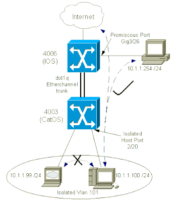
此文件使用以下網路設定:

在此場景中,隔離VLAN(101)中的裝置相互之間在第2層通訊受到限制。但是,裝置可以連線到網際網路。此外,4006上的連線埠Gig 3/26具有混雜指定。此可選配置允許GigabitEthernet 3/26上的裝置連線到隔離VLAN中的所有裝置。例如,此配置還允許將資料從所有PVLAN主機裝置備份到管理工作站。混雜埠的其他用途包括連線到外部路由器、LocalDirector、網路管理裝置和其他裝置。
配置主要和隔離VLAN
執行以下步驟建立主VLAN和輔助VLAN,以及將各種埠繫結到這些VLAN。這些步驟包括CatOS和Cisco IOS®軟體的示例。針對您的作業系統安裝,發出適當的命令集。
-
建立主PVLAN。
-
CatOS
Switch_CatOS> (enable) set vlan primary_vlan_id
pvlan-type primary name primary_vlan


 !--- Note: This command must be on one line.

VTP advertisements transmitting temporarily stopped,
and will resume after the command finishes.
Vlan 100 configuration successful
-
Cisco IOS軟體
Switch_IOS(config)#vlan primary_vlan_id

Switch_IOS(config-vlan)#private-vlan primary

Switch_IOS(config-vlan)#name primary-vlan

Switch_IOS(config-vlan)#exit
-
-
建立隔離VLAN或VLAN。
-
CatOS
Switch_CatOS> (enable) set vlan secondary_vlan_id
pvlan-type isolated name isolated_pvlan


 !--- Note: This command must be on one line.

VTP advertisements transmitting temporarily stopped,
and will resume after the command finishes.
Vlan 101 configuration successful
-
Cisco IOS軟體
Switch_IOS(config)#vlan secondary_vlan_id

Switch_IOS(config-vlan)#private-vlan isolated

Switch_IOS(config-vlan)#name isolated_pvlan

Switch_IOS(config-vlan)#exit
-
-
將隔離VLAN/VLAN繫結到主VLAN。
-
CatOS
Switch_CatOS> (enable) set pvlan primary_vlan_id secondary_vlan_id Vlan 101 configuration successful Successfully set association between 100 and 101. -
Cisco IOS軟體
Switch_IOS(config)#vlan primary_vlan_id

Switch_IOS(config-vlan)#private-vlan association secondary_vlan_id

Switch_IOS(config-vlan)#exit
-
-
驗證專用VLAN配置。
-
CatOS
Switch_CatOS> (enable) show pvlan
Primary Secondary Secondary-Type   Ports
------- --------- ---------------- ------------
100     101       isolated
-
Cisco IOS軟體
Switch_IOS#show vlan private-vlan
Primary  Secondary  Type              Ports
------- --------- ----------------- -------
100     101       isolated
-
為PVLAN分配埠

提示:實施此過程之前,請發出show PVLAN capability mod/port(用於CatOS)命令,以確定某個埠能否變為PVLAN埠。

注意:執行此過程的步驟1之前,請在介面配置模式下發出switchport 命令,將埠配置為第2層交換介面。
-
在所有適當的交換機上配置主機埠。
-
CatOS
Switch_CatOS> (enable) set pvlan primary_vlan_id secondary_vlan_id mod/port !--- Note: This command must be on one line. Successfully set the following ports to Private Vlan 100,101: 2/20 -
Cisco IOS軟體
Switch_IOS(config)#interface gigabitEthernet mod/port

Switch_IOS(config-if)#switchport private-vlan host
primary_vlan_id secondary_vlan_id


 !--- Note: This command must be on one line.

Switch_IOS(config-if)#switchport mode private-vlan host
Switch_IOS(config-if)#exit
-
-
在其中一個交換機上配置promiscuous port。
-
CatOS
Switch_CatOS> (enable) set pvlan mapping primary_vlan_id secondary_vlan_id mod/port


!--- Note: This command must be on one line.

Successfully set mapping between 100 and 101 on 3/26
注意:對於Catalyst 6500/6000(當Supervisor引擎將CatOS作為系統軟體運行時),如果您希望VLAN之間的第3層交換機,則Supervisor引擎上的MSFC埠(15/1或16/1)必須是混雜的。
-
-
Cisco IOS軟體
Switch_IOS(config)#interface interface_type mod/port

Switch_IOS(config-if)#switchport private-vlan
mapping primary_vlan_id secondary_vlan_id


 !--- Note: This command must be on one line.

Switch_IOS(config-if)#switchport mode private-vlan promiscuous
Switch_IOS(config-if)#end
第3層配置
此選用段落說明允許PVLAN輸入流量路由的設定步驟。如果只需要啟用第2層連線,則可以忽略此階段。
-
按照與配置普通第3層路由相同的方式配置VLAN介面。
此配置涉及:
-
配置IP地址
-
使用no shutdown 命令啟用介面
-
驗證VLAN資料庫中是否存在該VLAN
有關配置示例,請參閱VLAN/VTP技術支援。
-
-
將您要路由的輔助VLAN對映到主VLAN。
Switch_IOS(config)#interface vlan primary_vlan_id

Switch_IOS(config-if)#private-vlan mapping secondary_vlan_list

Switch_IOS(config-if)#end

註:只為主VLAN配置第3層VLAN介面。使用隔離或社群VLAN配置,隔離VLAN和社群VLAN的VLAN介面處於非活動狀態。
-
發出show interfaces private-vlan mapping(Cisco IOS軟體)或show pvlan mapping(CatOS)命令以驗證對映。
-
如果配置對映後需要修改輔助VLAN清單,請使用add(增加)或remove(刪除)關鍵字。
Switch_IOS(config-if)#private-vlan mapping add secondary_vlan_list

or
Switch_IOS(config-if)#private-vlan mapping remove secondary_vlan_list

注意:對於帶有MSFC的Catalyst 6500/6000交換機,請確保從Supervisor引擎到路由引擎的埠(例如,埠15/1或16/1)是混雜的。
cat6000> (enable) set pvlan mapping primary_vlan secondary_vlan 15/1
Successfully set mapping between 100 and 101 on 15/1
發出命令show pvlan mapping 以驗證對映。
cat6000> (enable) show pvlan mapping
Port Primary Secondary
---- ------- ---------
15/1  100      101
組態
本文件使用以下組態:
| 接入層(Catalyst 4003:CatOS) |
|---|
Access_Layer> (enable) show config This command shows non-default configurations only. Use 'show config all' to show both default and non-default configurations. ............. !--- Output suppressed. #system set system name Access_Layer ! #frame distribution method set port channel all distribution mac both ! #vtp set vtp domain Cisco set vtp mode transparent set vlan 1 name default type ethernet mtu 1500 said 100001 state active set vlan 100 name primary_for_101 type ethernet pvlan-type primary mtu 1500 said 100100 state active !--- This is the primary VLAN 100. |
| 核心(Catalyst 4006:Cisco IOS軟體) |
|---|
Core#show running-config Building configuration... !--- Output suppressed. ! hostname Core ! vtp domain Cisco vtp mode transparent !--- VTP mode is transparent, as PVLANs require. ip subnet-zero ! vlan 2-4,6,10-11,20-22,26,28 ! vlan 100 name primary_for_101 private-vlan primary private-vlan association 101 ! vlan 101 name isolated_under_100 private-vlan isolated ! interface Port-channel1 !--- This is the port channel for interface GigabitEthernet3/1 |
跨多台交換機的專用VLAN
專用VLAN可透過兩種方法跨多台交換機使用。本節將討論以下方法:
常規TRUNK
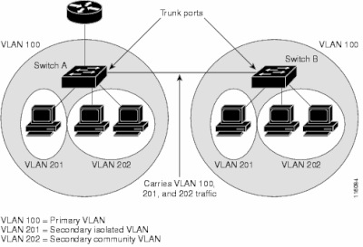
與常規VLAN一樣,PVLAN可以跨越多台交換機。TRUNK埠將主VLAN和輔助VLAN傳輸到相鄰交換機。中繼埠與任何其它VLAN一樣處理專用VLAN。跨多台交換機的PVLAN的一個功能是,一台交換機中隔離埠的流量無法到達另一台交換機的隔離埠。
在所有中間裝置(包括沒有PVLAN埠的裝置)上配置PVLAN,以維護PVLAN配置的安全性,並避免使用配置為PVLAN的VLAN。 中繼埠傳輸來自常規VLAN以及主VLAN、隔離VLAN和社群VLAN的流量。

提示:如果接受中繼的兩台交換機都支援PVLAN,則Cisco建議使用標準TRUNK埠。
 在第2層網路的所有交換機上手動配置PVLAN
由於VTP不支援PVLAN,因此您必須在第2層網路中的所有交換機上手動配置PVLAN。如果您未在網路中的某些交換機中配置主要和輔助VLAN關聯,則這些交換機中的第2層資料庫不會合併。這種情況可能導致這些交換機上出現不必要的PVLAN流量泛洪。
專用VLAN中繼
一個PVLAN中繼埠可以承載多個輔助和非PVLAN。在PVLAN中繼埠上使用輔助或常規VLAN標籤接收和傳輸資料包。
僅支援IEEE 802.1q封裝。隔離的中繼埠允許您將中繼上的所有輔助埠的流量合併。混雜中繼埠允許您將本拓撲中所需的多個混雜埠組合到承載多個主VLAN的單個中繼埠中。
當您預計使用專用VLAN隔離主機埠傳輸多個VLAN(正常VLAN或多個專用VLAN域)時,請使用隔離的專用VLAN中繼埠。因此,連線不支援專用VLAN的下游交換機時非常有用。
專用VLAN混雜中繼用於通常使用專用VLAN混雜主機埠但需要承載多個VLAN的情況,即普通VLAN或多個專用VLAN域。因此,對於連線不支援專用VLAN的上游路由器而言,該命令非常有用。
其他資訊
有關詳細資訊,請參閱專用VLAN中繼。
要將介面配置為PVLAN中繼埠,請參閱將第2層介面配置為PVLAN中繼埠。
要將介面配置為混合中繼埠,請參閱將第2層介面配置為混合中繼埠。
驗證
使用本節內容,確認您的組態是否正常運作。
CatOS
-
show pvlan -顯示PVLAN配置。檢驗隔離VLAN和主VLAN是否相互關聯。此外,請驗證是否顯示任何主機埠。
-
show pvlan mapping -以混合埠上的配置顯示PVLAN對映。
Cisco IOS軟體
-
show vlan private-vlan — 顯示PVLAN資訊,其中包括相關聯的埠。
-
show interfacemod/portswitchport -顯示特定於介面的資訊。檢驗運行模式和運行PVLAN設定是否正確。
-
show interfaces private-vlan mapping -顯示已配置的PVLAN對映。
驗證程式
請完成以下步驟:
-
驗證交換機上的PVLAN配置。
檢查以確定主PVLAN和輔助PVLAN是否相互關聯/對映。此外,驗證是否包含必要的埠。
Access_Layer> (enable) show pvlan
Primary Secondary Secondary-Type   Ports
------- --------- ---------------- ------------
 100     101       isolated         2/20

Core#show vlan private-vlan

Primary Secondary Type              Ports
------- --------- ----------------- -----------
100     101       isolated          Gi3/26
-
驗證混合埠的正確配置。
此輸出指示,埠操作模式為promiscuous,而運行的VLAN為100和101。
Core#show interface gigabitEthernet 3/26 switchport
Name: Gi3/26
Switchport: Enabled
Administrative Mode: private-Vlan promiscuous
Operational Mode: private-vlan promiscuous
Administrative Trunking Encapsulation: negotiate
Operational Trunking Encapsulation: native
Negotiation of Trunking: Off
Access Mode VLAN: 1 (default)
Trunking Native Mode VLAN: 1 (default)
Voice VLAN: none
Administrative Private VLAN Host Association: none
Administrative Private VLAN Promiscuous Mapping: 100
(primary_for_101) 101 (isolated_under_100)
Private VLAN Trunk Native VLAN: none
Administrative Private VLAN Trunk Encapsulation: dot1q
Administrative Private VLAN Trunk Normal VLANs: none
Administrative Private VLAN Trunk Private VLANs: none
Operational Private VLANs:
100 (primary_for_101) 101 (isolated_under_100)
Trunking VLANs Enabled: ALL
Pruning VLANs Enabled: 2-1001
Capture Mode Disabled
Capture VLANs Allowed: ALL
-
起始從主機連線埠到混合連線埠的網際網路控制訊息通訊協定(ICMP) ping封包。
請記住,由於兩台裝置位於同一個主VLAN中,因此它們必須位於同一個子網中。
host_port#show arp Protocol Address Age (min) Hardware Addr Type Interface Internet 10.1.1.100 - 0008.a390.fc80 ARPA FastEthernet0/24
!--- The Address Resolution Protocol (ARP) table on the client indicates
!--- that no MAC addresses other than the client addresses are known.
host_port#ping 10.1.1.254 Type escape sequence to abort. Sending 5, 100-byte ICMP Echos to 10.1.1.254, timeout is 2 seconds: .!!!! Success rate is 80 percent (4/5), round-trip min/avg/max = 1/2/4 ms !--- The ping is successful. The first ping fails while the
!--- device attempts to map via ARP for the peer MAC address. host_port#show arp Protocol Address Age (min) Hardware Addr Type Interface Internet 10.1.1.100 - 0008.a390.fc80 ARPA FastEthernet0/24 Internet 10.1.1.254 0 0060.834f.66f0 ARPA FastEthernet0/24 !--- There is now a new MAC address entry for the peer. -
在主機埠之間啟動ICMP ping。
在本示例中,host_port_2 (10.1.1.99)嘗試對host_port (10.1.1.100)執行ping操作。此ping失敗。但是,從另一個主機埠ping混雜埠仍然成功。
host_port_2#ping 10.1.1.100

Type escape sequence to abort.
Sending 5, 100-byte ICMP Echos to 10.1.1.100, timeout is 2 seconds:
.....
Success rate is 0 percent (0/5)

!--- The ping between host ports fails, which is desirable.


host_port_2#ping 10.1.1.254

Type escape sequence to abort.
Sending 5, 100-byte ICMP Echos to 10.1.1.254, timeout is 2 seconds:
!!!!
Success rate is 100 percent (5/5), round-trip min/avg/max = 4/4/4 ms

!--- The ping to the promiscuous port still succeeds.


host_port_2#show arp
Protocol  Address          Age (min)  Hardware Addr   Type   Interface
Internet  10.1.1.99               -   0005.7428.1c40  ARPA   Vlan1
Internet  10.1.1.254              2   0060.834f.66f0  ARPA   Vlan1

!--- The ARP table includes only an entry for this port and
!--- the promiscuous port.
疑難排解
排除PVLAN故障
本部分介紹PVLAN配置中出現的一些常見問題。
問題1
您將收到以下錯誤消息:「%PM-SP-3-ERR_INCOMP_PORT: <mod/port>設定為不活動,因為<mod/port>是中繼埠。」
此錯誤消息可能由於多種原因而顯示,如下面所述。
解釋- 1
由於硬體限制,當同一COIL ASIC中的一個連線埠為主幹、SPAN目的地或混雜PVLAN連線埠時,Catalyst 6500/6000 10/100-Mbps模組會限制隔離或群體VLAN連線埠的組態。(COIL ASIC控制大多數模組上的12個埠和Catalyst 6548模組上的48個埠。) 本文檔規則和限制部分中的表提供了Catalyst 6500/6000 10/100-Mbps模組上埠限制的細分資訊。
解決程式- 1
如果該埠不支援PVLAN,請選擇該模組或另一個模組上不同ASIC上的埠。要將埠重新啟用,請刪除隔離VLAN或社群VLAN埠配置並發出shutdown命令和no shutdown命令。
解釋- 2
埠是手動配置還是預設為dynamic desirable或dynamic auto模式。
解決程式- 2
使用switchport mode access命令將埠配置為接入模式。要將埠重新啟用,請發出shutdown命令和no shutdown命令。

注意:在Cisco IOS軟體版本12.2(17a)SX及更高版本中,12埠限制不適用於WS-X6548-RJ-45、WS-X6548-RJ-21和WS-X6524-100FX-MM乙太網交換模組。
問題2
在PVLAN配置過程中,出現以下消息之一:
Cannot add a private vlan mapping to a port with another Private port in
the same ASIC.
Failed to set mapping between <vlan> and <vlan> on <mod/port>
Port with another Promiscuous port in the same ASIC cannot be made
Private port.
Failed to add ports to association.
說明
由於硬體限制,當同一COIL ASIC中的一個連線埠為主幹、SPAN目的地或混雜PVLAN連線埠時,Catalyst 6500/6000 10/100-Mbps模組會限制隔離或群體VLAN連線埠的組態。(COIL ASIC控制大多數模組上的12個埠和Catalyst 6548模組上的48個埠。) 本文檔規則和限制部分中的表提供了Catalyst 6500/6000 10/100-Mbps模組上埠限制的細分資訊。
解決程式
發出show pvlan capability命令(CatOS),此命令可指示某個埠能否變為PVLAN埠。如果該特定埠不支援PVLAN,請選擇該模組或另一模組上不同ASIC上的埠。

注意:在Cisco IOS軟體版本12.2(17a)SX及更高版本中,12埠限制不適用於WS-X6548-RJ-45、WS-X6548-RJ-21和WS-X6524-100FX-MM乙太網交換模組。
問題3
您不能在部分平台上配置PVLAN。
解析
驗證該平台是否支援PVLAN。開始配置之前,請參閱專用VLAN Catalyst交換機支援表,以確定您的平台和軟體版本是否支援PVLAN。
問題4
在Catalyst 6500/6000 MSFC上,無法對連線到交換機上隔離埠的裝置執行ping操作。
解析
在Supervisor Engine上,驗證通往MSFC (15/1或16/1)的埠是否為混雜埠。
cat6000> (enable) set pvlan mapping primary_vlan secondary_vlan 15/1
Successfully set mapping between 100 and 101 on 15/1
並請按照本文檔中第3層配置部分的規定,對MSFC上的VLAN介面進行配置。
問題5
發出no shutdown 命令後,無法啟用隔離VLAN或社群VLAN的VLAN介面。
解析
由於PVLAN的性質,您不能啟用隔離VLAN或社群VLAN的VLAN介面。您只能啟用屬於主VLAN的VLAN介面。
問題6
在帶有MSFC/MSFC2的Catalyst 6500/6000裝置上,在第3層PVLAN介面上獲知的ARP條目不會過期。
解析
在第3層專用VLAN介面上獲取的ARP條目是粘滯ARP條目,不會過期。使用同一IP地址連線新裝置會生成一條消息,並且不會建立ARP條目。因此,如果MAC地址更改,您必須手動刪除PVLAN埠ARP條目。要手動增加或刪除PVLAN ARP條目,請發出以下命令:
Router(config)#no arp 10.1.3.30
IP ARP:Deleting Sticky ARP entry 10.1.3.30
Router(config)#arp 10.1.3.30 0000.5403.2356 arpa
IP ARP:Overwriting Sticky ARP entry 10.1.3.30, hw:00d0.bb09.266e by
hw:0000.5403.2356
另一個選項是在Cisco IOS軟體版本12.1(11b)E及更高版本中發出no ip sticky-arp命令。
相關資訊
修訂記錄
| 修訂 | 發佈日期 | 意見 |
|---|---|---|
4.0 |
12-Sep-2024 |
更新的SEO和格式化。 |
3.0 |
13-Sep-2023 |
已從「相關資訊」部分刪除損壞的連結。 |
2.0 |
26-Jun-2023 |
重新認證 |
1.0 |
24-Feb-2003 |
初始版本 |
 意見
意見