Catalyst 9000交換器上的MST疑難排解
下載選項
無偏見用語
本產品的文件集力求使用無偏見用語。針對本文件集的目的,無偏見係定義為未根據年齡、身心障礙、性別、種族身分、民族身分、性別傾向、社會經濟地位及交織性表示歧視的用語。由於本產品軟體使用者介面中硬式編碼的語言、根據 RFP 文件使用的語言,或引用第三方產品的語言,因此本文件中可能會出現例外狀況。深入瞭解思科如何使用包容性用語。
關於此翻譯
思科已使用電腦和人工技術翻譯本文件,讓全世界的使用者能夠以自己的語言理解支援內容。請注意,即使是最佳機器翻譯,也不如專業譯者翻譯的內容準確。Cisco Systems, Inc. 對這些翻譯的準確度概不負責,並建議一律查看原始英文文件(提供連結)。
目錄
簡介
本文檔介紹瞭解MST在具有PVST或其他區域的拓撲中如何工作所需的基本概念。
必要條件
需求
思科建議您瞭解以下主題:
- 快速PVST(每VLAN快速生成樹)
採用元件
本文中的資訊係根據以下軟體和硬體版本:
-
Catalyst 9300.
- 從17.3列車開始。
本文中的資訊是根據特定實驗室環境內的裝置所建立。文中使用到的所有裝置皆從已清除(預設)的組態來啟動。如果您的網路運作中,請確保您瞭解任何指令可能造成的影響。
相關產品
本檔案也適用於以下硬體:
-
所有Catalyst 9000系列。
背景資訊
技術
開始和應用任何型別的故障排除之前,請考慮以下術語:
| 概念 |
說明 |
| STP例項 |
例項是在CPU中運行的會話: 在PVST上,一個VLAN是中的例項。 在MST上,例項是一組VLAN。本文檔將使用基於此含義的術語例項。 |
| IST |
IST(內部生成樹)也稱為例項0或MSTI0: — 這是一個特殊的例項。 IST是傳送和接收BPDU的唯一生成樹例項。所有其他生成樹例項資訊都包含在M記錄中,這些記錄封裝在MSTP BPDU中。因為MSTP BPDU會傳送所有例項的資訊。這是唯一具有計時器相關引數的例項。當MST與其他區域和跨距樹狀目錄版本通訊時,IST或MSTI0的設定是用於通訊的。 |
| MSTI |
MSTI代表多個生成樹例項。從1到15 思科實施支援16個例項:一個IST(例項0)和15個MSTI。 |
| 地區 |
運行MST的一組交換機。所有交換機都具有相同的MST配置。 |
| CIST和CST |
- 通用生成樹將MST區域和單個生成樹互連。 — 通用和內部生成樹是每個MST區域和通用生成樹中IST的集合。 |
| 區域根 |
這是除例項0之外的區域中每個例項的選舉過程。 如果需要,可以在生成樹區域中為每個例項指定一個不同的根。 如果認為IST BPDU中的資訊具有執行正常生成樹選擇所需的資訊,則會完成此操作。 CIST根網橋在預標準實施中稱為IST主網橋。如果CIST根橋位於區域中,則區域根橋為CIST根橋。 否則,區域根是該區域中距離CIST根最近的交換機。區域根作為IST的根網橋。 |
| M記錄 |
由於只有一個BPDU,並且BPDU反映收斂例項0所需的資訊,因此需要使用另一個機制來形成其他例項的根。 這稱為M記錄。每個M-Record內部都包含單個例項的所有生成樹資訊。 |
| 爭議 |
Disrupt機制是一種內建的單向鏈路檢測機制。802.1d原始版本(2004年RSTP實際上已整合到802.1d標準中)或PVST中不能提供此功能。 當接收到具有指定狀態並且處於學習和轉發狀態的下級BPDU時,觸發爭執機制。 |
| 建議書/協定 |
本建議協議機制是RSTP最重要的更改之一。 這實際上使快速生成樹變得快速。 當下級交換機識別出此埠不是根網橋,並且有到根的最佳路徑時,它不再設定建議位,並轉換到根狀態和轉發。 |
| 共用網段 |
RSTP/MST將半雙工鏈路置於「共用」狀態。這意味著不會進行建議協定流程。 由於該序列旨在快速啟動P2P鏈路,過早轉換到正向狀態可能會形成環路。這可在生成樹的show命令中看到 您可以在介面上輸入spanning-tree link-type point-to-point以強制其處於P2P狀態,請仔細使用。 |
| 多個區域 |
·當MST配置不匹配時,將確定多個區域。 ·通過MSTI0 BPDU在區域之間選擇CIST ·對於其他裝置,多個區域顯示為每個區域的一個邏輯交換機。 |
| 邊界埠 |
這些連線埠位於區域範圍內,通常在這些連線埠上會收到非MST BPDU,因此此連線埠上無法使用MST。 PVST模擬是MST和PVST可以在同一網路上工作的方式。 |
| PVST模擬 |
在某些場景中,例如遷移或網路拓撲更改,會同時發現多個STP風格,並且MST區域連線到另一個域。 例如,從PVST+更改為MST的網路不能同時修改所有交換機。此外,還需要同時使用MST和PVST+。 由於PVST+無法處理MST BPUS,因此兩者之間有一個相容性機制,因此兩種協定可以互動。這種相容性機制稱為PVST模擬。 |
| PVST模擬故障 |
如果未滿足PVST模擬上規定的規則 |
限制
-
支援PVST+、快速PVST+和MSTP,但任何時候只能有一個版本處於活動狀態。(例如,所有VLAN運行PVST+,所有VLAN運行快速PVST+,或所有VLAN運行MSTP。)
-
不支援MST配置的VLAN中繼協定(VTP)傳播。
疑難排解
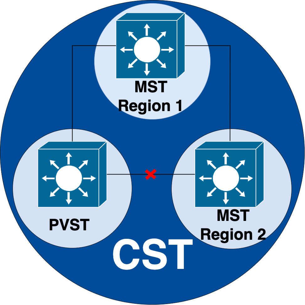
目標是使MST區域像虛擬CST網橋一樣運行,從區域外部的角度。
其他交換機(位於不同的區域或PVST域中)將MST區域視為只有一個交換機,因為RootID和根路徑開銷保持不變。
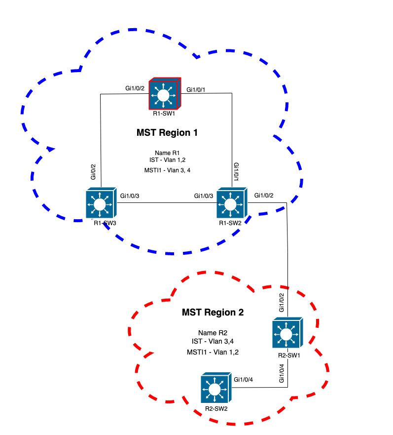
MST(單區域)
拓撲

組態
為了正確收斂,必須在MST區域下的所有交換機上以相同方式配置這三個屬性。命令在MST配置模式下應用。
- 名稱
- 修訂版號
- VLAN到例項的對映
spanning-tree mst configuration
name <region name>
revision <number>
instance <number> vlan <vlan number>
使用以下命令驗證屬性配置:
show running-config | section span
示例:區域1中交換機1、2和3的屬性配置
R1-SW1
R1-SW1#show running-config | section spann
spanning-tree mode mst
spanning-tree extend system-id
spanning-tree mst configuration
 name R1               <---
 revision 1            <---
 instance 1 vlan 3-4   <---
R1-SW2
R1-SW2#show running-config | section spann
spanning-tree mode mst
spanning-tree extend system-id
spanning-tree mst configuration
 name R1
 revision 1
 instance 1 vlan 3-4
R1-SW3
R1-SW3#show running-config | section spann
spanning-tree mode mst
spanning-tree extend system-id
spanning-tree mst configuration
 name R1
 revision 1
 instance 1 vlan 3-4
驗證
在MST遷移期間,無需更改STP模式即可配置MST引數。
請遵循以下建議,以避免由於配置錯誤而導致可能的網路中斷。
- 提交前檢查MST配置。
- 提交後檢查MST配置
提交前檢查MST配置。
此檢查是在尚未應用跨距樹狀目錄模式mst時進行的。
show spanning-tree mst
show current
show spanning-tree mst configuration digest
注意:show current僅在MST配置模式(生成樹mst配置子模式)下可用
示例:對於區域1中的交換機1
驗證STP模式尚未處於MST模式
R1-SW1#show spanning-tree mst
% Switch is not in mst mode   <--
驗證當前MST配置
R1-SW1(config-mst)#show current
Current MST configuration
Name      [R1]
Revision  1     Instances configured 2

Instance  Vlans mapped
--------  ---------------------------------------------------------------------
0         1-2,6-4094
1         3-4
-------------------------------------------------------------------------------
注意:show current僅在MST配置模式下可用。
註:show span mst configuration和show current是相同的命令。
驗證摘要雜湊
R1-SW1#show spanning-tree mst configuration digest
% Switch is not in mst mode                          <--
Name [R1]
Revision 1 Instances configured 2
Digest 0xA423B8DBB209CCF6560F55618AB58726            <--
Pre-std Digest 0x8C9BE88BBC9B84CB8AED635EE008436A
註:摘要輸出用於讓您知道交換機是否已經處於MST模式。摘要雜湊不會更改,即使MST模式尚未啟用。
註:Catalyst 9000交換機運行IEEE標準MST協定。因此,您必須將注意力放在Digest雜湊上,而不是Pre-std Digest
提交後檢查MST配置
show current
show pending
show spanning-tree mst configuration digest
abort
註:show pending(以及show current)僅在MST配置模式下可用
show current輸出會顯示退出MST子模式(也就是應用配置更改時)後的MST配置,而show pending輸出會顯示最近配置但未應用的MST配置。
如果由於任何原因需要恢復配置更改,並且您仍處於MST子模式下,則可以應用abort命令,該命令會從MST子模式退出而不應用更改。
註:show pending(以及show current)僅在MST配置模式下可用
示例:對於區域1中的交換機1
請注意,當前配置和待定配置相同,這意味著未進行任何更改。
摘要雜湊與上一個輸出中驗證的雜湊相同。
R1-SW1(config)#spanning-tree mst configuration
R1-SW1(config-mst)#show current
Current MST configuration
Name      [R1]
Revision  1     Instances configured 2

Instance  Vlans mapped
--------  ---------------------------------------------------------------------
0         1-2,5-4094
1         3-4
-------------------------------------------------------------------------------

R1-SW1(config-mst)#show pending
Pending MST configuration
Name      [R1]
Revision  1     Instances configured 2

Instance  Vlans mapped
--------  ---------------------------------------------------------------------
0         1-2,5-4094
1         3-4
-------------------------------------------------------------------------------

R1-SW1(config-mst)#do show spanning-tree mst configuration digest
Name      [R1]
Revision  1     Instances configured 2
Digest          0xA423B8DBB209CCF6560F55618AB58726   <--
Pre-std Digest  0x8C9BE88BBC9B84CB8AED635EE008436A
將建立新例項並將VLAN 5對映到它。這一次show current輸出不會顯示最近有條件的新例項,但會顯示show pending。這是意料之中的。
請注意,摘要雜湊沒有更改。這是因為新配置僅在退出MST配置模式(生成樹mst配置子模式)時才適用
 R1-SW1(config-mst)#instance 2 vlan 5       <--
R1-SW1(config-mst)#show current
Current MST configuration
Name      [R1]
Revision  1     Instances configured 2

Instance  Vlans mapped
--------  ---------------------------------------------------------------------
0         1-2,5-4094
1         3-4
-------------------------------------------------------------------------------

R1-SW1(config-mst)#show pending
Pending MST configuration
Name      [R1]
Revision  1     Instances configured 3

Instance  Vlans mapped
--------  ---------------------------------------------------------------------
0         1-2,6-4094
1         3-4
2         5     <--
-------------------------------------------------------------------------------

R1-SW1(config-mst)#do show spanning-tree mst configuration digest
Name      [R1]
Revision  1     Instances configured 2
Digest          0xA423B8DBB209CCF6560F55618AB58726     <--
Pre-std Digest  0x8C9BE88BBC9B84CB8AED635EE008436A
退出MST配置模式後,將反映所做的更改。還會重新計算摘要雜湊,以便與所做的新更改相匹配。
R1-SW1(config-mst)#exit
R1-SW1(config)#spanning-tree mst configuration
R1-SW1(config-mst)#show current
Current MST configuration
Name      [R1]
Revision  1     Instances configured 3

Instance  Vlans mapped
--------  ---------------------------------------------------------------------
0         1-2,6-4094
1         3-4
2         5       <--
-------------------------------------------------------------------------------

R1-SW1(config-mst)#show pending
Pending MST configuration
Name      [R1]
Revision  1     Instances configured 3

Instance  Vlans mapped
--------  ---------------------------------------------------------------------
0         1-2,6-4094
1         3-4
2         5     <--
-------------------------------------------------------------------------------


R1-SW1(config-mst)#do show spanning-tree mst configuration digest
Name      [R1]
Revision  1     Instances configured 3
Digest          0x083305551908B9A2CC50B482DC577B8F     <--
Pre-std Digest  0xA8AC09BDF2942058FAF4CE727C9D258F
這些命令有助於驗證MST引數和收斂性。此外,它們還提供與MST計時器、成本等相關的資訊。
show spanning-tree pathcost method
show spanning-tree root
show spanning-tree summary
show spanning-tree mst
show spanning-tree interface <interface>
註:show spanning-tree mst和show spanning-tree 是等效的
示例:對於區域1中的交換機1
測量路徑成本的方法有兩種:短(傳統)和長。始終最好是沿第2層網路保持同構狀態。如果運行long pathcost方法,請通過所有在STP上運行的交換機執行。
R1-SW1#show spanning-tree pathcost method
Spanning tree default pathcost method used is long  <--
此輸出現在允許您使用路徑開銷方法,還允許您知道交換機運行標準MST協定並使用擴展系統ID(使用MST時必須使用)。
R1-SW1#show spanning-tree summary
Switch is in mst mode (IEEE Standard)               <--
Root bridge for: none
EtherChannel misconfig guard            is enabled
Extended system ID                      is enabled  <--
Portfast Default                        is disabled
PortFast BPDU Guard Default            is disabled
Portfast BPDU Filter Default           is disabled
Loopguard Default                      is disabled
UplinkFast                              is disabled
BackboneFast                            is disabled
Configured Pathcost method used is long             <--

Name                   Blocking Listening Learning Forwarding STP Active
---------------------- -------- --------- -------- ---------- ----------
MST0                         0         0        0          3          3
MST1                         0         0        0          3          3
---------------------- -------- --------- -------- ---------- ----------
2 msts                       0         0        0          6          6
在以下輸出中可以觀察到網橋和根ID、優先順序、成本、埠角色和狀態以及VLAN對映:
R1-SW1#show spanning-tree mst

##### MST0    vlans mapped:   1-2,5-4094
Bridge        address 3473.2db8.be80  priority      32768 (32768 sysid 0)
Root          address f04a.021e.9500  priority      24576 (24576 sysid 0)
              port    Gi1/0/2         path cost     0
Regional Root address f04a.021e.9500  priority      24576 (24576 sysid 0)
                                      internal cost 20000     rem hops 19
Operational   hello time 2 , forward delay 15, max age 20, txholdcount 6
Configured    hello time 2 , forward delay 15, max age 20, max hops    20

Interface                        Role Sts Cost      Prio.Nbr Type
----------------                 ---- --- --------- -------- --------------------------------
Gi1/0/1                          Desg FWD 20000     128.1    P2p
Gi1/0/2                          Root FWD 20000     128.2    P2p
Gi1/0/4                          Desg FWD 20000     128.4    P2p

##### MST1    vlans mapped:   3-4
Bridge        address 3473.2db8.be80  priority      32769 (32768 sysid 1)
Root          address f04a.021e.9500  priority      24577 (24576 sysid 1)
              port    Gi1/0/2         cost          20000     rem hops 19

Interface                        Role Sts Cost      Prio.Nbr Type
----------------                 ---- --- --------- -------- --------------------------------
Gi1/0/1                          Desg FWD 20000     128.1    P2p
Gi1/0/2                          Root FWD 20000     128.2    P2p
Gi1/0/4                          Desg FWD 20000     128.4    P2p
此命令從介面而不是每個例項的角度顯示STP角色狀態、優先順序和鏈路型別。
R1-SW1#show spanning-tree interface gigabitEthernet 1/0/1

Mst Instance        Role Sts Cost      Prio.Nbr Type
------------------- ---- --- --------- -------- --------------------------------
MST0                Desg FWD 20000     128.1    P2p
MST1                Desg FWD 20000     128.1    P2p

R1-SW1#show spanning-tree interface gigabitEthernet 1/0/2

Mst Instance        Role Sts Cost      Prio.Nbr Type
------------------- ---- --- --------- -------- --------------------------------
MST0                Root FWD 20000     128.2    P2p
MST1                Root FWD 20000     128.2    P2p
區域之間的同步
區域2已新增到拓撲中。目的是檢驗兩個不同區域如何互動和收斂的過程。只有邊界交換機才會發生在此通訊中。
因為連結的兩端具有相同的通訊程式。本節重點介紹R1-SW2的show spanning-tree mst輸出以及從資料包捕獲獲得的兩個BPDU。
拓撲

驗證
這是區域1的R1-SW2與區域2的R2-SW1之間的初始通訊。一旦兩台裝置之間建立連線,它們就會傳送BPDU。
將重點放在R2-SW1的介面Gi1/0/2上,該介面處於阻塞(BLK)初始狀態。請記住,交換機埠在選舉過程中進入BLK狀態。
R2-SW1#show spanning-tree mst

MST0
! Output omitted for brevity

Interface           Role Sts Cost      Prio.Nbr Type
------------------- ---- --- --------- -------- --------------------------------
Gi1/0/2             Desg BLK 20000     128.2    P2p
Gi1/0/4             Root FWD 20000     128.4    P2p

MST1
! Output omitted for brevity

Interface           Role Sts Cost      Prio.Nbr Type
------------------- ---- --- --------- -------- --------------------------------
Gi1/0/2             Desg BLK 20000     128.2    P2p
Gi1/0/4             Root FWD 20000     128.4    P2p
在資料包捕獲中,可以看到第一個BPDU,其中埠角色標誌顯示為「指定」和「建議」。
這表示通訊已啟動,兩個連線埠都已啟動同步程式,以建立通訊協定並設定連線埠角色和狀態。一切從提案機制開始。
IEEE 802.3 Ethernet
    Destination: Spanning-tree-(for-bridges)_00 (01:80:c2:00:00:00)
    Source: Cisco_05:d6:02 (f0:4a:02:05:d6:02)
    Length: 121
Logical-Link Control
Spanning Tree Protocol
    Protocol Identifier: Spanning Tree Protocol (0x0000)
    Protocol Version Identifier: Multiple Spanning Tree (3)
    BPDU Type: Rapid/Multiple Spanning Tree (0x02)
    BPDU flags: 0x0e, Port Role: Designated, Proposal
        0... .... = Topology Change Acknowledgment: No
        .0.. .... = Agreement: No
        ..0. .... = Forwarding: No
        ...0 .... = Learning: No
        .... 11.. = Port Role: Designated (3)
        .... ..1. = Proposal: Yes
        .... ...0 = Topology Change: No
    Root Identifier: 24576 / 0 / f0:4a:02:1e:95:00
    Root Path Cost: 20004
    Bridge Identifier: 32768 / 0 / a0:f8:49:10:47:80
    Port identifier: 0x8002
    Message Age: 2
    Max Age: 20
    Hello Time: 2
    Forward Delay: 15
    Version 1 Length: 0
    Version 3 Length: 80
    MST Extension
交換器之間交換BPDU後,狀態變為learning(LRN)。
在R2-SW1收到前面顯示的第一個BPDU後,LRN狀態是阻塞狀態之後的第一個過渡狀態。
R2-SW1#show spanning-tree mst

MST0
! Output omitted for brevity

Interface           Role Sts Cost      Prio.Nbr Type
------------------- ---- --- --------- -------- --------------------------------
Gi1/0/2             Desg LRN 20000     128.2    P2p
Gi1/0/4             Root FWD 20000     128.4    P2p

MST1
! Output omitted for brevity

Interface           Role Sts Cost      Prio.Nbr Type
------------------- ---- --- --------- -------- --------------------------------
Gi1/0/2             Desg LRN 20000     128.2    P2p
Gi1/0/4             Root FWD 20000     128.4    P2p
一旦某個對等體建立協定並發生同步(接受鄰居作為到根的上級路徑),鏈路會立即轉換到轉發狀態。
在這裡,您可以觀察設定了標誌作為學習的BPDU,它還包括拓撲更改通知標誌,該標誌在埠從LRN轉換到轉發(FWR)時觸發。
在此狀態下,MST確定埠是否參與幀轉發(狀態BLK)。
IEEE 802.3 Ethernet
Logical-Link Control
Spanning Tree Protocol
    Protocol Identifier: Spanning Tree Protocol (0x0000)
    Protocol Version Identifier: Multiple Spanning Tree (3)
    BPDU Type: Rapid/Multiple Spanning Tree (0x02)
    BPDU flags: 0x3d, Forwarding, Learning, Port Role: Designated, Topology Change
        0... .... = Topology Change Acknowledgment: No
        .0.. .... = Agreement: No
        ..1. .... = Forwarding: Yes
        ...1 .... = Learning: Yes
        .... 11.. = Port Role: Designated (3)
        .... ..0. = Proposal: No
        .... ...1 = Topology Change: Yes
    Root Identifier: 24576 / 0 / f0:4a:02:1e:95:00
    Root Path Cost: 20004
    Bridge Identifier: 32768 / 0 / a0:f8:49:10:47:80
    Port identifier: 0x8002
    Message Age: 2
    Max Age: 20
    Hello Time: 2
    Forward Delay: 15
    Version 1 Length: 0
    Version 3 Length: 80
    MST Extension
最後,交換機埠在遍歷建立網路拓撲所涉及的所有狀態後進入轉發狀態。
這是連線埠的最後一個狀態,具有指定角色(Desg)和狀態FDW。
R2-SW1#show spanning-tree mst

MST0
! Output omitted for brevity

Interface           Role Sts Cost      Prio.Nbr Type
------------------- ---- --- --------- -------- --------------------------------
Gi1/0/2             Desg FWD 20000     128.2    P2p
Gi1/0/4             Root FWD 20000     128.4    P2p


MST1
! Output omitted for brevity

Interface           Role Sts Cost      Prio.Nbr Type
------------------- ---- --- --------- -------- --------------------------------
Gi1/0/2             Desg FWD 20000     128.2    P2p
Gi1/0/4             Root FWD 20000     128.4    P2p
調試
在R2-SW1和R1-SW2之間的通訊期間啟用了這些錯誤。
debug spanning-tree mstp roles
debug spanning-tree mstp tc
debug spanning-tree mstp boundary
範例:
R2-SW1#show debugging
Packet Infra debugs:

Ip Address                                               Port
------------------------------------------------------|----------

Multiple Spanning Tree:
  MSTP port ROLES changes debugging is on
  MSTP Topology Change notifications debugging is on
  MSTP port BOUNDARY flag changes debugging is on
已觀察到的日誌
%LINK-3-UPDOWN: Interface GigabitEthernet1/0/2, changed state to down
%LINK-3-UPDOWN: Interface GigabitEthernet1/0/2, changed state to up
MST[0]: Gi1/0/2 is now designated port
MST[0]: Gi1/0/2 becomes designated - clearing BOUNDARY flag
MST[1]: Gi1/0/2 is now designated port
MST[0]: port Gi1/0/2 received external tc
MST[0]: port Gi1/0/2 received external tc
MST[1]: port Gi1/0/2 received tc
MST[0]: port Gi1/0/2 received external tc
MST[0]: port Gi1/0/2 received external tc
MST[1]: port Gi1/0/2 received tc
MST[0]: port Gi1/0/2 received external tc
MST[0]: port Gi1/0/2 received external tc
MST[1]: port Gi1/0/2 received tc
MST[0]: port Gi1/0/2 initiating tc
MST[1]: port Gi1/0/2 initiating tc
MST[0]: port Gi1/0/2 received external tc
MST[0]: port Gi1/0/2 received external tc
MST[1]: port Gi1/0/2 received tcsho span
%LINEPROTO-5-UPDOWN: Line protocol on Interface GigabitEthernet1/0/2, changed state to up
MST[0]: port Gi1/0/3 received internal tc
MST[0]: port Gi1/0/3 received internal tc
MST[0]: port Gi1/0/3 received internal tc
PVST模擬故障
PVST模擬是MST用於與非MST交換機通訊的機制。
PVST交換機無法識別MST BPDU,因為它們完全不同。這就是理解PVST和MST BPDU之間的差異的重要原因。
PVST BPDU與MST BPDU比較
捕獲了兩個BPDU,一個用於PVST,另一個用於MST,請觀察它們之間的差異。
PVST
- PVST為交換機上配置的每個VLAN傳送一個BPDU。因此,配置了100個VLAN意味著100個BPDU通過所有埠傳送,以構建自己的無環拓撲。
- PVST基於傳統STP
Ethernet II, Src: Cisco_06:19:01 (f0:4a:02:06:19:01), Dst: PVST+ (01:00:0c:cc:cc:cd)
    Destination: PVST+ (01:00:0c:cc:cc:cd)
    Source: Cisco_06:19:01 (f0:4a:02:06:19:01)
    Type: 802.1Q Virtual LAN (0x8100)
802.1Q Virtual LAN, PRI: 7, DEI: 0, ID: 3
    111. .... .... .... = Priority: Network Control (7)
    ...0 .... .... .... = DEI: Ineligible
    .... 0000 0000 0011 = ID: 3
    Length: 50
Logical-Link Control
    DSAP: SNAP (0xaa)
    SSAP: SNAP (0xaa)
    Control field: U, func=UI (0x03)
    Organization Code: 00:00:0c (Cisco Systems, Inc)
    PID: PVSTP+ (0x010b)
Spanning Tree Protocol
    Protocol Identifier: Spanning Tree Protocol (0x0000)
    Protocol Version Identifier: Spanning Tree (0)
    BPDU Type: Configuration (0x00)
    BPDU flags: 0x01, Topology Change
        0... .... = Topology Change Acknowledgment: No
        .... ...1 = Topology Change: Yes
    Root Identifier: 32768 / 0 / 68:9e:0b:a0:f5:80
        Root Bridge Priority: 32768
        Root Bridge System ID Extension: 0
        Root Bridge System ID: Cisco_a0:f5:80 (68:9e:0b:a0:f5:80)
    Root Path Cost: 20000
    Bridge Identifier: 32768 / 0 / f0:4a:02:06:19:00
        Bridge Priority: 32768
        Bridge System ID Extension: 0
        Bridge System ID: Cisco_06:19:00 (f0:4a:02:06:19:00)
    Port identifier: 0x8001
    Message Age: 1
    Max Age: 20
    Hello Time: 2
    Forward Delay: 15
    Originating VLAN (PVID): 3
        Type: Originating VLAN (0x0000)
        Length: 2
        Originating VLAN: 3
MST
- MST為交換機上配置的所有MST例項傳送一個BPDU。這要歸功於具有所有例項資訊的MST擴展(M記錄)。
- MST基於RSTP,這意味著此協定的所有固有機制都繼承到MST。
- 計時器由IST定義,並影響區域內所有其他例項
IEEE 802.3 Ethernet
    Destination: Spanning-tree-(for-bridges)_00 (01:80:c2:00:00:00)
    Source: Cisco_b8:be:81 (34:73:2d:b8:be:81)
    Length: 121
Logical-Link Control
    DSAP: Spanning Tree BPDU (0x42)
    SSAP: Spanning Tree BPDU (0x42)
    Control field: U, func=UI (0x03)
Spanning Tree Protocol
    Protocol Identifier: Spanning Tree Protocol (0x0000)
    Protocol Version Identifier: Multiple Spanning Tree (3)
    BPDU Type: Rapid/Multiple Spanning Tree (0x02)
    BPDU flags: 0x0e, Port Role: Designated, Proposal
        0... .... = Topology Change Acknowledgment: No
        .0.. .... = Agreement: No
        ..0. .... = Forwarding: No
        ...0 .... = Learning: No
        .... 11.. = Port Role: Designated (3)
        .... ..1. = Proposal: Yes
        .... ...0 = Topology Change: No
    Root Identifier: 32768 / 0 / 34:73:2d:b8:be:80
        Root Bridge Priority: 32768
        Root Bridge System ID Extension: 0
        Root Bridge System ID: Cisco_b8:be:80 (34:73:2d:b8:be:80)
    Root Path Cost: 0
    Bridge Identifier: 32768 / 0 / 34:73:2d:b8:be:80
        Bridge Priority: 32768
        Bridge System ID Extension: 0
        Bridge System ID: Cisco_b8:be:80 (34:73:2d:b8:be:80)
    Port identifier: 0x8001
    Message Age: 0
    Max Age: 20
    Hello Time: 2
    Forward Delay: 15
    Version 1 Length: 0
    Version 3 Length: 80
    MST Extension
        MST Config ID format selector: 0
        MST Config name: R1
        MST Config revision: 1
        MST Config digest: a423b8dbb209ccf6560f55618ab58726
        CIST Internal Root Path Cost: 0
        CIST Bridge Identifier: 32768 / 0 / 34:73:2d:b8:be:80
            CIST Bridge Priority: 32768
            CIST Bridge Identifier System ID Extension: 0
            CIST Bridge Identifier System ID: Cisco_b8:be:80 (34:73:2d:b8:be:80)
        CIST Remaining hops: 20
        MSTID 1, Regional Root Identifier 32768 / 34:73:2d:b8:be:80
            MSTI flags: 0x0e, Port Role: Designated, Proposal
                0... .... = Topology Change Acknowledgment: No
                .0.. .... = Agreement: No
                ..0. .... = Forwarding: No
                ...0 .... = Learning: No
                .... 11.. = Port Role: Designated (3)
                .... ..1. = Proposal: Yes
                .... ...0 = Topology Change: No
            1000 .... = Priority: 0x8
            .... 0000 0000 0001 = MSTID: 1
            Regional Root: Cisco_b8:be:80 (34:73:2d:b8:be:80)
            Internal root path cost: 0
            Bridge Identifier Priority: 8
            Port identifier priority: 8
            Remaining hops: 20
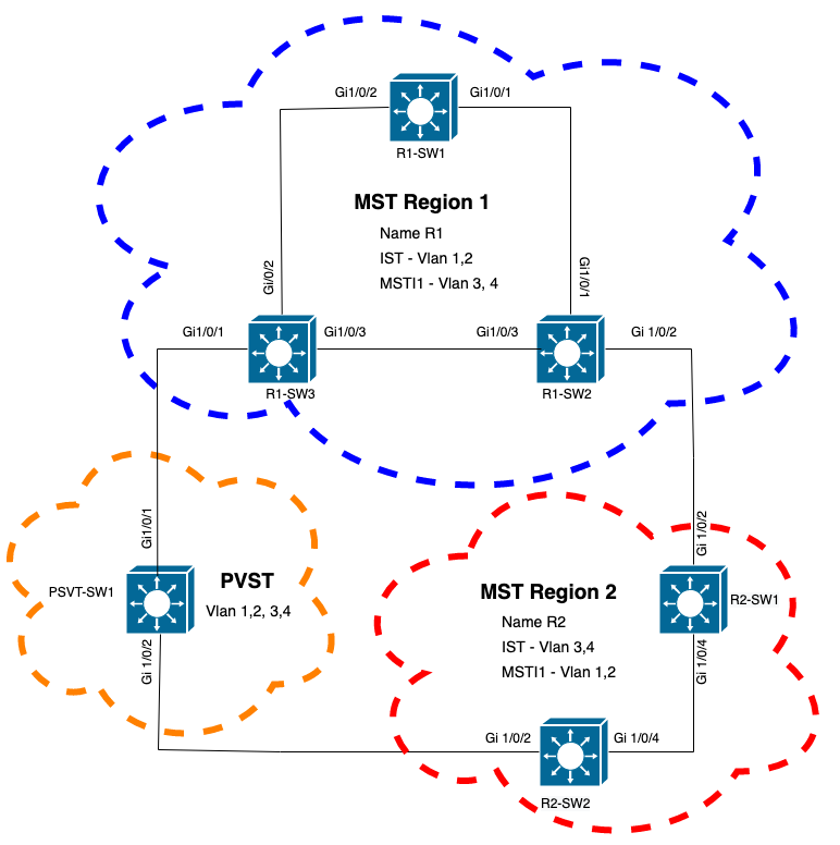
拓撲
帶有PVST的交換機已新增到網路中。它將區域1和區域2互連。

驗證
連線PVST交換機後,來自區域1的交換機R1-SW3的邊界埠(gi1/0/1)進入PVST不一致並阻塞埠。
R1-SW3#show spanning-tree mst

##### MST0    vlans mapped:   1-2,5-4094
Bridge        address f04a.021e.9500  priority      32768 (32768 sysid 0)
Root          address 689e.0ba0.f580  priority      16385 (16384 sysid 1)
              port    Gi1/0/1         path cost     20000
Regional Root this switch
Operational   hello time 2 , forward delay 15, max age 20, txholdcount 6
Configured    hello time 2 , forward delay 15, max age 20, max hops    20

Interface                        Role Sts Cost      Prio.Nbr Type
----------------                 ---- --- --------- -------- --------------------------------
Gi1/0/1                          Root BKN*20000     128.1    P2p Bound(PVST) *PVST_Inc
Gi1/0/2                          Desg FWD 20000     128.2    P2p
Gi1/0/3                          Desg FWD 20000     128.3    P2p

##### MST1    vlans mapped:   3-4
Bridge        address f04a.021e.9500  priority      32769 (32768 sysid 1)
Root          address 3473.2db8.be80  priority      32769 (32768 sysid 1)
              port    Gi1/0/2         cost          20000     rem hops 19

Interface                        Role Sts Cost      Prio.Nbr Type
----------------                 ---- --- --------- -------- --------------------------------
Gi1/0/1                          Mstr BKN*20000     128.1    P2p Bound(PVST) *PVST_Inc
Gi1/0/2                          Root FWD 20000     128.2    P2p
Gi1/0/3                          Altn BLK 20000     128.3    P2p
注意:在R2-SW2上觀察到來自區域2(另一個邊界埠)的類似輸出。
.
之所以發生這種情況,是因為這些規則都違反了
- 如果CIST的根網橋在非MST區域內,則在該域內從VLAN 2開始的生成樹優先順序必須優於(小於)VLAN 1。
- 如果CIST的根網橋位於MST區域內,則非MST網域中定義的VLAN 2之前的生成樹優先順序必須比CIST根的生成樹優先順序更差(更大)。
請檢視在交換機上設定的無效配置以解決此問題:
案例1.PVST交換機是VLAN 2-4的根,但VLAN 2-4的優先順序比VLAN 1差(更高)。在這種情況下,除PVST交換機之外的所有交換機都具有預設STP優先順序(32768)
PVST-SW1# show run | inc span
spanning-tree mode pvst
spanning-tree extend system-id
spanning-tree vlan 1 priority 4096    <--
spanning-tree vlan 2-4 priority 16384 <--
spanning-tree mst configuration
觀察到的日誌:
%SPANTREE-2-PVSTSIM_FAIL: Blocking root port Gi1/0/1: Inconsitent inferior PVST BPDU received on VLAN 2, claiming root 16386:689e.0ba0.f580
案例2.PVST交換機不是VLAN 1的根,但是VLAN 2-4的優先順序比根高(更低)。在這種情況下,root具有預設的優先順序24576。這表示根網橋不是所有VLAN的根
PVST-SW1#show run | inc span
spanning-tree mode pvst
spanning-tree extend system-id
spanning-tree vlan 1 prio 32768       <-- higher priority than the root
spanning-tree vlan 2-4 priority 16384 <--  lower priority than the root
spanning-tree mst configuration
觀察到的日誌:
%SPANTREE-2-PVSTSIM_FAIL: Blocking root port Gi1/0/1: Inconsistent inferior PVST BPDU received on VLAN 2, claiming root 40962:689e.0ba0.f580
考慮上述規則後,您就可以使用這些有效配置來刪除此問題。
案例1.
PVST-SW1# show run | inc span
spanning-tree mode pvst
spanning-tree extend system-id
spanning-tree vlan 1 priority 16384  <-- VLAN 1 has a higher priority than all other VLANs
spanning-tree vlan 2-4 priority 4096 <--
spanning-tree mst configuration
觀察到的日誌:
%SPANTREE-2-PVSTSIM_OK: PVST Simulation nconsistency cleared on port GigabitEthernet1/0/1.
案例2.
PVST-SW1#show run | inc span
spanning-tree mode pvst
spanning-tree extend system-id
spanning-tree vlan 1 prio 32768       <-- higher priority than the root
spanning-tree vlan 2-4 priority 40960 <--  higher priority than the root
spanning-tree mst configuration
觀察到的日誌:
%SPANTREE-2-PVSTSIM_OK: PVST Simulation nconsistency cleared on port GigabitEthernet1/0/1.
調試
如果無法捕獲資料包,則使用BPDU調試驗證BPDU。
debug spanning-tree mstp bpdu receive
debug spanning-tree mstp bpdu transmit
示例:對於連線到PVST交換機的區域2中的交換機2
R2-SW2#debug spanning-tree mstp bpdu receive
MSTP BPDUs RECEIVEd dump debugging is on
R2-SW2#debug spanning-tree mstp bpdu transmit
MSTP BPDUs TRANSMITted dump debugging is on
R2-SW2#debug condition interface gigabitEthernet 1/0/2 <-- interface facing PVST switch

R2-SW2#show logging
! Output omitted for brevity
%LINK-3-UPDOWN: Interface GigabitEthernet1/0/2, changed state to down
%LINK-3-UPDOWN: Interface GigabitEthernet1/0/2, changed state to up
MST[0]:-TX> Gi1/0/2 BPDU Prot:0 Vers:3 Type:2
MST[0]: Role :Desg Flags[P] Age:2 RemHops:19
MST[0]: CIST_root:16385.689e.0ba0.f580 Cost :40000
MST[0]: Reg_root :32768.f04a.0205.d600 Cost :20000
MST[0]: Bridge_ID:32768.a0f8.4910.4780 Port_ID:32770
MST[0]: max_age:20 hello:2 fwdelay:15
MST[0]: V3_len:80 region:R2 rev:1 Num_mrec: 1
MST[1]:-TX> Gi1/0/2 MREC
MST[1]: Role :Desg Flags[MAP] RemHops:20
MST[1]: Root_ID :32769.a0f8.4910.4780 Cost :0
MST[1]: Bridge_ID:32769.a0f8.4910.4780 Port_id:130
%LINEPROTO-5-UPDOWN: Line protocol on Interface GigabitEthernet1/0/2, changed state to up
MST[0]:-TX> Gi1/0/2 BPDU Prot:0 Vers:3 Type:2
MST[0]: Role :Desg Flags[P] Age:2 RemHops:19
MST[0]: CIST_root:16385.689e.0ba0.f580 Cost :40000
MST[0]: Reg_root :32768.f04a.0205.d600 Cost :20000
MST[0]: Bridge_ID:32768.a0f8.4910.4780 Port_ID:32770
MST[0]: max_age:20 hello:2 fwdelay:15
MST[0]: V3_len:80 region:R2 rev:1 Num_mrec: 1
MST[1]:-TX> Gi1/0/2 MREC
MST[1]: Role :Desg Flags[MAP] RemHops:20
MST[1]: Root_ID :32769.a0f8.4910.4780 Cost :0
MST[1]: Bridge_ID:32769.a0f8.4910.4780 Port_id:130
MST[0]:


      MST[0]: Role :Desg Flags[FLTc] Age:0


      MST[0]: CIST_root:16385.689e.0ba0.f580 Cost :0


      MST[0]: Bridge_ID:16385.689e.0ba0.f580 Port_ID:32770


      MST[0]: max_age:20 hello:2 fwdelay:15
P2P糾紛
拓撲

說明
在本節中,您可能會發現兩台裝置無法建立協定並正確設定埠狀態的問題。
R1-SW1#show spanning-tree mst

##### MST0    vlans mapped:   1-2,5-4094
Bridge        address 3473.2db8.be80  priority      32768 (32768 sysid 0)
Root          address 689e.0ba0.f580  priority      4097  (4096 sysid 1)
              port    Gi1/0/2         path cost     20000
Regional Root address f04a.021e.9500  priority      24576 (24576 sysid 0)
                                      internal cost 20000     rem hops 19
Operational   hello time 2 , forward delay 15, max age 20, txholdcount 6
Configured    hello time 2 , forward delay 15, max age 20, max hops    20

Interface                        Role Sts Cost      Prio.Nbr Type
----------------                 ---- --- --------- -------- --------------------------------
Gi1/0/1                          Desg FWD 20000     128.1    P2p
Gi1/0/2                          Root FWD 20000     128.2    P2p
Gi1/0/4                          Desg BLK 20000     128.2    P2p Dispute

##### MST1    vlans mapped:   3-4
Bridge        address 3473.2db8.be80  priority      32769 (32768 sysid 1)
Root          address f04a.021e.9500  priority      24577 (24576 sysid 1)
              port    Gi1/0/2         cost          20000     rem hops 19

Interface                        Role Sts Cost      Prio.Nbr Type
----------------                 ---- --- --------- -------- --------------------------------
Gi1/0/1                          Desg FWD 20000     128.1    P2p
Gi1/0/2                          Root FWD 20000     128.2    P2p
Gi1/0/4                          Desg BLK 20000     128.2    P2p Dispute
R1-SW1(根)發現新裝置已連線到它。因此,它會傳送其BPDU並將自身定義為根。
它收到一個BPDU,指定在鏈路的另一端,將標誌設定為埠角色:指定、轉發和學習。
這表示新交換器連線的狀態具有到達根的更好路徑。但是,這是不可能的,因為R1-SW1是根,並且沒有更好的路徑可達該根。
由於兩台交換機無法建立協定並正確設定埠(因為兩台BPDU都顯示到根的更好路徑),因此R1-SW1會假設新交換機沒有收到其BPDU,並將埠狀態設定為P2P爭議,以避免可能導致環路的單向場景。
MST方法
如本文檔所述,只要向網路新增更多交換機,MST就會更加複雜。因此,對同一網路採用不同的方法非常重要。
範例:
如果發現的問題不在MST區域內,而是在PVST域內,則您可以看到更寬的圖片並忽略MST區域內的任何內容(CST透視)。

另一方面,如果懷疑問題可能在MST區域之間或區域內部,則CIST可提供更好的視角。

如果需要,可以將重點放在交換機的埠角色和狀態上

相關資訊
- 瞭解多重生成樹通訊協定(802.1s)
- 第2層配置指南,Cisco IOS XE Amsterdam 17.3.x(Catalyst 9300交換機)
- 第2層和第3層配置指南,Cisco IOS XE Everest 16.5.1a(Catalyst 9300交換機)
- MST交換機上的PVST模擬
- 思科錯誤ID CSCvy02075 - 交換器轉送在處於封鎖狀態的BLK連線埠上接收的流量
修訂記錄
| 修訂 | 發佈日期 | 意見 |
|---|---|---|
1.0 |
26-Oct-2022 |
初始版本 |
 意見
意見