Configuring External Connectivity

Creating External VRFs

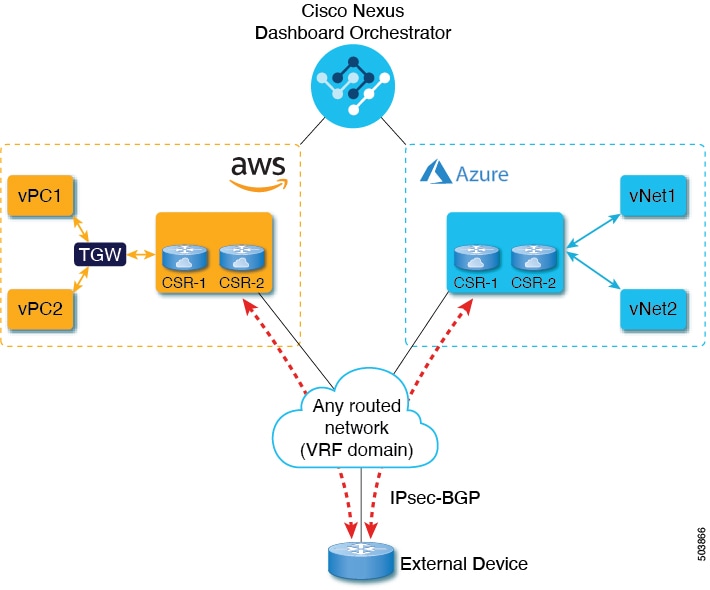
This section describes how to create an external VRF which will be used to establish connectivity to an external devices' subnets. You can follow the provided steps to provision an external VRF to multiple cloud sites.

Procedure


Step 1

Log in to the Cisco Nexus Dashboard Orchestrator GUI.

Step 2

In the Main menu, select Application Management > Schemas.

Step 3

Create a new schema and templates or select an existing schema where you will deploy the templates associated to the Infra tenant containing the external VRFs definition.

You can create a separate schema specifically for this use case, where you will define all templates associated to the Infra tenant and containing the external VRFs providing the connectivity to the external devices.

When creating the external VRF templates:

  • You must use separate templates for different types of cloud sites (AWS or Azure), but the templates can be part of the same schema and you can associate the same template to multiple cloud sites of the same type. In other words, you can create a single template for all AWS sites and another template for all Azure sites.

  • You must choose the ACI Multi-Cloud template type.

  • You must map the template to the infra tenant or the VRFs cannot be used for external connectivity.

  • You can use the same VRF name in both templates. We will use extVrf1 for the examples in this document.

Step 4

In the main pane, select +Create Object > VRF.

Step 5

Provide the Display Name for the VRF.

You can leave all other options at default values.

Note 

In the VRF's site local properties, do not attach this VRF to any regions. Any VRF that is created in the Infra tenant and is not attached to any region is treated as an external VRF and can be used for this use case.

Step 6

Assign the template that contains your external VRF to one or more cloud sites from which you will establish external connectivity.

Remember that you must assign the template only to one type of cloud sites (AWS or Azure), but you can assign the same template to multiple cloud sites of the same type.

Step 7

Deploy the templates to create the external VRF in the cloud sites.


Adding External Devices

This section describes how to provide information about your external devices to your Nexus Dashboard Orchestrator in the Orchestrator's Infra Config page.


Note

The following steps focus on the configurations required for this specific use case. Detailed information about all infra configuration settings is available in Cisco Nexus Dashboard Orchestrator Configuration Guides.


Procedure


Step 1

Log in to the Cisco Nexus Dashboard Orchestrator GUI.

Step 2

In the left navigation menu, select Infrastructure > Infra Configuration.

Step 3

In the main pane, click Configure Infra.

Step 4

In the left sidebar, select General Settings.

Step 5

Provide the External Devices information.

This step describes how to provide information about any external devices to which you want to configure connectivity from your cloud sites. The following diagram illustrates the external device in a typical topology:

  1. Select the External Devices tab.

  2. Click Add External Device.

    The Add External Device dialogue will open.

  3. Provide the Name, IP Address, and BGP Autonomous System Number for the device.

    The IP address you provide will be used as the tunnel peer address from the Cloud APIC's CSRs, not the device's management IP address. The connectivity will be established over public Internet using IPsec.

  4. Click the check mark icon to save the device information.

  5. Repeat this step for any additional external devices you want to add.

Step 6

Provide the IPsec Tunnel Subnet Pools information.

There are two types of subnet pools that you can provide here:

  • External Subnet Pool—used for connectivity between cloud site CSRs and other sites (cloud or on-premises).

    These are large global subnet pools that are managed by Nexus Dashboard Orchestrator. The Orchestrator, creates smaller subnets from these pools and allocates them to sites to be used for inter-site IPsec tunnels and external connectivity IPsec tunnels.

    You must provide at least one external subnet pool if you want to enable external connectivity from one or more of your cloud sites.

  • Site-Specific Subnet Pool—used for connectivity between cloud site CSRs and external devices.

    These subnets can be defined when the external connectivity IPsec tunnels must be in a specific range. For example, where a specific subnet is already being used to allocate IP addresses to the external router and you want to continue using those subnets for IPsec tunnels for NDO and cloud sites. These subnets are not managed by the Orchestrator and each subnet is assigned to a site in its entirety to be used locally for external connectivity IPsec tunnels.

    If you do not provide any named subnet pools but still configure connectivity between cloud site's CSRs and external devices, the external subnet pool will be used for IP allocation to the IPsec tunnels established between cloud site CSRs and external devices.

Note 

The minimum mask length for both subnet pools is /24.

To add one or more External Subnet Pools:

  1. Select the IPsec Tunnel Subnet Pools tab.

  2. In the External Subnet Pool area, click +Add IP Address to add one or more external subnet pools.

    This subnet will be used to address the IPsec tunnel interfaces and loopbacks of the Cloud Routers used for on-premises connectivity, which you previously configured in the Cloud APIC for inter-site connectivity in earlier Nexus Dashboard Orchestrator releases.

    The subnets must not overlap with other on-premises TEP pools, should not begin with 0.x.x.x or 0.0.x.x, and should have a network mask between /16 and /24, for example 10.12.0.0/16.

  3. Click the check mark icon to save the subnet information.

  4. Repeat these substeps for any additional subnet pools you want to add.

To add one or more Site-Specific Subnet Pool:

  1. Select the IPsec Tunnel Subnet Pools tab.

  2. In the Named Subnet Pool area, click +Add IP Address to add one or more external subnet pools.

    The Add Named Subnet Pool dialogue will open.

  3. Provide the subnet Name.

    You will be able to use the subnet pool's name to choose the pool from which to allocate the IP addresses later on, for example extSubPool1.

  4. Click +Add IP Address to add one or more subnet pools.

    The subnets must have a network mask between /16 and /24and not begin with 0.x.x.x or 0.0.x.x, for example 10.181.0.0/16.

  5. Click the check mark icon to save the subnet information.

    Repeat the steps if you want to add multiple subnets to the same named subnet pool.

  6. Click Save to save the named subnet pool.

  7. Repeat these substeps for any additional named subnet pools you want to add.


Configuring Site's External Connectivity

This section describes how to configure site-specific Infra settings for Cloud APIC sites.

Procedure


Step 1

In the left pane of the Fabric Connectivity Infra page, under Sites, select a specific cloud site.

This is the site from which you want to establish connectivity to an external device.

Step 2

Provide External Connectivity information.

You must complete this step to provide connectivity information to the external devices as part of this use case configuration.

  1. In the right <Site> Settings pane, select the External Connectivity tab.

  2. Click Add External Connection.

    The Add External Connectivity dialog will open.

  3. From the VRF dropdown, select the VRF you want to use for external connectivity.

    This is the VRF (extVrf1) which will be used to leak the cloud routes and which you already created in Creating External VRFs. The Regions section will display the cloud regions that contain the CSRs to which this configuration is applied.

  4. Click +Add External Device.

  5. From the Name dropdown in the External Devices section, select the external device.

    This is the external device which you added in the General Settings > External Devices list during general infra configuration and must already be defined as described in Adding External Devices.

  6. From the Tunnel IKE Version dropdown, pick the IKE version that will be used to establish the IPsec tunnel between the cloud site's CSRs and the external device.

  7. (Optional) From the Tunnel Subnet Pool dropdown, choose one of the site-specific subnet pools.

    Site-specific subnet pools are used to allocate IP addresses for IPsec tunnels between cloud site CSRs and external devices. If you do not provide any Site-Specific Subnet Pool subnet pools here, the External Subnet Pool subnet pool will be used for IP allocation.

    Providing a dedicated subnet pool for external device connectivity is useful for cases where a specific subnet is already being used to allocate IP addresses to the external router and you want to continue to use those subnets for IPsec tunnels for NDO and cloud sites.

    If you want to provide a specific subnet pool for this connectivity, it must already be created as described in Adding External Devices.

  8. (Optional) In the Pre-Shared Key field, provide the custom keys you want to use to establish the tunnel.

    If you do not provide a pre-shared key, Cloud APIC will generate one automatically on the CSR.

  9. If necessary, repeat the previous substeps for any additional external devices you want to add for the same external connection (same external VRF).

  10. If necessary, repeat this step for any additional external connections (different external VRFs).

    Note that there's a one-to-one relationship for tunnel endpoints between CSRs and external devices, so while you can create additional external connectivity using different external VRFs, you cannot create additional connectivity to the same external devices.


Deploying Infra Configuration

This section describes how to deploy the Infra configuration for the external connectivity from cloud sites.

Procedure


Step 1

In the top right of the main pane, choose Deploy > Deploy & Download External Device Config files.

The Deploy & Download External Device Config files option pushes the configuration to the Cloud APIC sites and enables the end-to-end interconnect from the cloud sites to the external devices.

In addition, this option downloads a zip file that contains configuration information that you will use to enable connectivity from external devices to the Cisco Cloud Services Router (CSR) deployed in your cloud sites. A followup screen appears that allows you to select all or some of the configuration files to download.

Step 2

In the confirmation window, click Yes.

The Deployment started, refer to left menu for individual site deployment status message will indicate that Infra configuration deployment began and you can verify each site's progress by the icon displayed next to the site's name in the left pane.


Deploying Configuration to External Devices

While the previous section described how to deploy infra configuration to the cloud sites' Cloud APICs to enable connectivity from the cloud sites to the external devices, this section describes how to enable connectivity from the external device to the cloud sites.

Procedure


Step 1

Gather the necessary information that you will need to enable connectivity from the external device.

You can get the required configuration details using either the Deploy & Download External Device Config files or the Download External Device Config files option in Nexus Dashboard Orchestrator as part of the procedures provided in Deploying Infra Configuration.

When you download the configuration files:

  • The number of files will match the number of sites that have external connectivity.

  • The file name affixes will match the site IDs.

    For example, <...>-2.config indicates the file is for a site with Site ID 2. The site ID is listed in each site's Fabric Connectivity Infra page in the Orchestrator GUI.

Step 2

Log into the external device.

Step 3

Configure the tunnels and BGP from the external device to the cloud site's CSRs.

When configuring external devices:

  • Depending on the specific requirements, the external subnets may or may not be in the same VRF with the tunnel interfaces

    If the external subnets are in different VRFs then proper route leaking must be configured on the external device

    Note 

    Note that the configuration downloaded from NDO only allows to establish IPsec and BGP connectivity. It does not provide any information on the route-leaking configuration within the external device itself.

  • Once the external subnets are advertised to the Cloud CSRs, NDO provisions the route leaking configuration to select the subnets to be imported into the user tenant VRF

  • The following examples assume BGP configuration is done in the external VRF (extVrf1) and the external subnets as well as tunnel interfaces on the external device are part of the same VRF.

The following example shows how to configure a single IPsec tunnel (Tunnel100) from an external device (in this case ASR1K) to a CSR:

Example:

crypto isakmp policy 1
 encr aes
 authentication pre-share
 group 2
 lifetime 28800
crypto isakmp keepalive 10 10 periodic
crypto isakmp aggressive-mode disable


crypto isakmp profile infra:extVrf1-100-ike
   keyring infra:extVrf1-100-ike
   match identity address 52.191.103.96 255.255.255.255 
   

crypto ipsec transform-set infra:extVrf1-100-ike esp-aes esp-sha-hmac 
 mode tunnel
crypto ipsec profile infra:extVrf1-100-ike
 set security-association lifetime kilobytes disable
 set security-association replay window-size 512 
 set transform-set infra:extVrf1-100-ike 
 set pfs group14


interface Loopback100
 vrf forwarding infra:extVrf1


interface Tunnel100
 description AZ-JEFF CSR-2
 vrf forwarding infra:extVrf1
 ip address 10.181.0.6 255.255.255.252
 ip mtu 1400
 ip tcp adjust-mss 1400
 tunnel source GigabitEthernet0/0/0
 tunnel mode ipsec ipv4
 tunnel destination 52.191.103.96
 tunnel protection ipsec profile infra:extVrf1-100-ike
end

The following example shows how to configure BGP:

Example:

router bgp 65320
!
 address-family ipv4 vrf infra:extVrf1
  network 172.16.8.0 mask 255.255.255.0        // In this case, 172.16.8.0 and 172.16.9.0
  network 172.16.9.0 mask 255.255.255.0        // are examples of external subnets
  redistribute connected
  neighbor 10.101.255.1 remote-as 65001
  neighbor 10.101.255.1 ebgp-multihop 255
  neighbor 10.101.255.1 activate
  neighbor 10.101.255.1 send-community both
  neighbor 10.101.255.5 remote-as 65001
  neighbor 10.101.255.5 ebgp-multihop 255
  neighbor 10.101.255.5 activate
  neighbor 10.101.255.5 send-community both
  neighbor 10.181.0.1 remote-as 65008
  neighbor 10.181.0.1 ebgp-multihop 255
  neighbor 10.181.0.1 activate
  neighbor 10.181.0.1 send-community both
  neighbor 10.181.0.5 remote-as 65008
  neighbor 10.181.0.5 ebgp-multihop 255
  neighbor 10.181.0.5 activate
  neighbor 10.181.0.5 send-community both
  maximum-paths 2
  distance bgp 20 200 20
 exit-address-family
Step 4

Repeat the previous steps for all external devices.


Configuring Route Leaking

This section describes how to create the route leak configurations on the cloud CSRs required for this use case. Note that if any route leaking on the external device itself is required for your specific use case, it must be configured independently.

Before you begin

You must have one or more cloud VRFs already configured in your cloud site. You will configure route leaking from the external VRF to an existing cloud VRF.

Procedure


Step 1

In the Main menu, select Application Management > Schemas.

Step 2

Configure route leaking from external VRF to a cloud VRF.

The following steps show how to configure the following route leaking:

  1. Open the schema where you created the Infra tenant template containing the external VRF.

  2. In the left sidebar under SITES, select that specific template associated to the cloud site.

  3. In the site-local properties, select the external VRF defined in the template.

    This is the VRF you created in Creating External VRFs and assigned to one or more external devices in Configuring Site's External Connectivity.

  4. In the VRF's right-hand properties sidebar, click +Add Leak Route.

    The Add Leak Routes dialog will open.

  5. In the Add Leak Routes dialog's settings area, click Select a VRF and choose a cloud VRF.

    The goal of this step is to leak routes from the external VRF to the cloud VRFs, so select the cloud VRF to which you want to leak routes from the external VRF whose properties you are configuring.

  6. In the Add Leak Routes dialog, choose whether you want to Leak All routes or limit it to a specific Subnet IP.

    If you select Leak All, the subnet IP will be populated with 0.0.0.0/0 to leak all routes.

    If you choose to limit which routes to leak, click +Add Subnet IP and provide the subnet from your external VRF which you want to be reachable from the cloud VRF, for example 172.16.8.0/24. Click the checkmark icon to save the subnet information.

  7. Click Save to save the route leak configuration.

  8. Select the template and click Deploy to deploy the configuration.

Step 3

Configure route leaking from a cloud VRF to the external VRF.

The following steps show how to configure the route leaking in the other direction:

  1. Open the schema which contains the template that defines your cloud VRF.

  2. In the left sidebar under SITES, select the specific cloud site.

  3. In the site-local properties, select the cloud VRF.

  4. In the VRF's right-hand properties sidebar, click +Add Leak Route.

    The Add Leak Routes dialog will open.

  5. In the Add Leak Routes dialog's settings area, click Select a VRF and choose the external VRF.

    The goal of this step is to leak routes from the cloud VRF to the external VRF, so select the external VRF that you created in Creating External VRFs.

  6. In the Add Leak Routes dialog, choose whether you want to Leak All routes or limit it to a specific Subnet IP.

    If you select Leak All, the subnet IP will be populated with 0.0.0.0/0 to leak all routes.

    If you choose to limit which routes to leak, click +Add Subnet IP and provide the subnet from your cloud VRF which you want to be reachable from the external network, for example 81.0.1.0/24. Click the checkmark icon to save the subnet information.

  7. Click Save to save the route leak configuration.

  8. Select the template and click Deploy to deploy the configuration.


Creating External EPG

This section describes how to create an external EPG in the Infra template using subnet selection. We will use this external EPG to represent the external networks, then configure and apply contracts between the external EPG and the cloud EPG to allow communication between the endpoints in your cloud site and the external networks.

Procedure


Step 1

In the Main menu, select Application Management > Schemas.

Step 2

Select the schema and the template that contains your external VRFs.

You can create similar configurations for both (AWS and Azure) Infra templates, but we recommend using different application profile names in the next step to avoid any possible confusion.

Step 3

Create an Application Profile in the template.

You will need to associate the external EPG you create with an application profile.

Step 4

Create and configure an External EPG.

  1. Select Create Object > External EPGs.

  2. In the external EPG's properties sidebar, select CLOUD for Site Type.

  3. From the Application Profile dropdown, select the profile you created in the previous step.

  4. From the Virtual Routing and Forwarding dropdown, select the external VRF you created.

Step 5

Configure the external EPG's site-local properties.

  1. In the left sidebar, select the template under a site to which it is assigned.

  2. In the template's site-local properties, select External-Site for Route Reachability.

  3. Click Add Selector.

  4. In the Add New Endpoint Selector dialog, provide the external subnet.

    This is an external subnet that requires connectivity to the cloud site, for which you configured route leaking in the previous section. For example, 172.16.8.0/24.

Step 6

Deploy the templates to create the external EPG in the cloud site.


Applying Contract Between External EPG and Cloud EPG

This section describes how to apply a contract to allow communication between the endpoints in your cloud site and the external networks.

Before you begin

You must have one or more cloud EPGs already configured in your cloud site.

Procedure


Step 1

In the Main menu, select Application Management > Schemas.

Step 2

Create a contract and assign it to the cloud EPG.

  1. Select the schema and the template that contains your existing cloud EPG.

  2. Create the contract you will use for this use case.

    If you already have an existing contract you want to apply for communication between the external network and the Cloud EPG, you can skip this step.

    Otherwise, create a contract and the required filters as you typically would for any inter-EPG communication in Cisco ACI fabrics.

  3. Assign the contract to the cloud EPG.

    You can decide which of the two EPGs (cloud EPG and external EPG) will be the provider and which will be the consumer based on your specific use case.

Step 3

Assign the contract to the External EPG.

  1. Select the schema and the template where you created your external EPG.

  2. Assign the contract to the external EPG.

    If you configured your cloud EPG to be the provider, choose consumer for the external EPG; otherwise, if the cloud EPG is the consumer, choose provider.

Step 4

Deploy the templates.