Information About STP Extensions
 Note |
See the Cisco Nexus 9000 Series NX-OS Interfaces Configuration Guide, for information on creating Layer 2 interfaces. |
Cisco has added extensions to STP that enhances loop prevention, protects against some possible user misconfigurations, and provides better control over the protocol parameters. Although, in some cases, similar functionality may be incorporated into the IEEE 802.1w Rapid Spanning Tree Protocol (RSTP) standard, we recommend using these extensions. All of these extensions, except PVST Simulation, can be used with both Rapid PVST+ and MST. You use PVST Simulation only with MST.
The available extensions are spanning tree edge ports (which supply the functionality previously known as PortFast), Bridge Assurance, BPDU Guard, BPDU Filtering, Loop Guard, Root Guard, and PVT Simulation. Many of these features can be applied either globally or on specified interfaces.
Note |
Spanning tree is used to refer to IEEE 802.1w and IEEE 802.1s. If the text is discussing the IEEE 802.1D Spanning Tree Protocol, 802.1D is stated specifically. |
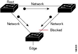
STP Port Types
You can configure a spanning tree port as an edge port, a network port, or a normal port. A port can be in only one of these states at a given time. The default spanning tree port type is normal.
Edge ports, which are connected to Layer 2 hosts, can be either an access port or a trunk port.
Note |
If you configure a port connected to a Layer 2 switch or bridge as an edge port, you might create a bridging loop. |
Network ports are connected only to Layer 2 switches or bridges.
Note |
If you mistakenly configure ports that are connected to Layer 2 hosts, or edge devices, as spanning tree network ports, those ports will automatically move into the blocking state. |
STP Edge Ports
You connect STP edge ports only to Layer 2 hosts. The edge port interface immediately transitions to the forwarding state, without moving through the blocking or learning states. (This immediate transition was previously configured as the Cisco-proprietary feature PortFast.)
Interfaces that are connected to Layer 2 hosts should not receive STP bridge protocol data units (BPDUs).
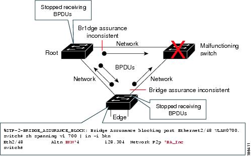
Bridge Assurance
You can use Bridge Assurance to protect against certain problems that can cause bridging loops in the network. Specifically, you use Bridge Assurance to protect against a unidirectional link failure or other software failure and a device that continues to forward data traffic when it is no longer running the spanning tree algorithm.
Note |
Bridge Assurance is supported only by Rapid PVST+ and MST. Bridge Assurance takes 2 seconds to kick in on a regular link and ~84 seconds on a VPC peer-link. |
Bridge Assurance is enabled by default and can only be disabled globally. Also, Bridge Assurance can be enabled only on spanning tree network ports that are point-to-point links. Finally, both ends of the link must have Bridge Assurance enabled. If the device on one side of the link has Bridge Assurance enabled and the device on the other side either does not support Bridge Assurance or does not have this feature enabled, the connecting port is blocked.
With Bridge Assurance enabled, BPDUs are sent out on all operational network ports, including alternate and backup ports, for each hello time period. If the port does not receive a BPDU for a specified period, the port moves into the blocking state and is not used in the root port calculation. Once that port receives a BPDU, it resumes the normal spanning tree transitions.
BPDU Guard
Enabling BPDU Guard shuts down that interface if a BPDU is received.
You can configure BPDU Guard at the interface level. When configured at the interface level, BPDU Guard shuts the port down as soon as the port receives a BPDU, regardless of the port type configuration.
When you configure BPDU Guard globally, it is effective only on operational spanning tree edge ports. In a valid configuration, Layer 2 LAN edge interfaces do not receive BPDUs. A BPDU that is received by an edge Layer 2 LAN interface signals an invalid configuration, such as the connection of an unauthorized device. BPDU Guard, when enabled globally, shuts down all spanning tree edge ports when they receive a BPDU.
BPDU Guard provides a secure response to invalid configurations, because you must manually put the Layer 2 LAN interface back in service after an invalid configuration.
Note |
When enabled globally, BPDU Guard applies to all operational spanning tree edge interfaces. |
BPDU Filtering
You can use BPDU Filtering to prevent the device from sending or even receiving BPDUs on specified ports.
When configured globally, BPDU Filtering applies to all operational spanning tree edge ports. You should connect edge ports only to hosts, which typically drop BPDUs. If an operational spanning tree edge port receives a BPDU, it immediately returns to a normal spanning tree port type and moves through the regular transitions. In that case, BPDU Filtering is disabled on this port, and spanning tree resumes sending BPDUs on this port.
In addition, you can configure BPDU Filtering by the individual interface. When you explicitly configure BPDU Filtering on a port, that port does not send any BPDUs and drops all BPDUs that it receives. You can effectively override the global BPDU Filtering setting on individual ports by configuring the specific interface. This BPDU Filtering command on the interface applies to the entire interface, whether the interface is trunking or not.
 Caution |
Use care when configuring BPDU Filtering per interface. If you explicitly configure BPDU Filtering on a port that is not connected to a host, it can result in bridging loops because the port will ignore any BPDU that it receives and go to forwarding. |
This table lists all the BPDU Filtering combinations.
|
BPDU Filtering Per Port Configuration |
BPDU Filtering Global Configuration |
STP Edge Port Configuration |
BPDU Filtering State |
|---|---|---|---|
|
Default 1 |
Enable |
Enable |
Enable 2 |
|
Default |
Enable |
Disable |
Disable |
|
Default |
Disable |
Not applicable |
Disable |
|
Disable |
Not applicable |
Not applicable |
Disable |
|
Enable |
Not applicable |
Not applicable |
Enable |
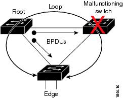
Loop Guard
Loop Guard helps prevent bridging loops that could occur because of a unidirectional link failure on a point-to-point link.
An STP loop occurs when a blocking port in a redundant topology erroneously transitions to the forwarding state. Transitions are usually caused by a port in a physically redundant topology (not necessarily the blocking port) that stops receiving BPDUs.
When you enable Loop Guard globally, it is useful only in switched networks where devices are connected by point-to-point links. On a point-to-point link, a designated bridge cannot disappear unless it sends an inferior BPDU or brings the link down. However, you can enable Loop Guard on shared links per interface,
You can use Loop Guard to determine if a root port or an alternate/backup root port receives BPDUs. If the port that was previously receiving BPDUs is no longer receiving BPDUs, Loop Guard puts the port into an inconsistent state (blocking) until the port starts to receive BPDUs again. If such a port receives BPDUs again, the port—and link—is deemed viable again. The protocol removes the loop-inconsistent condition from the port, and the STP determines the port state because the recovery is automatic.
Loop Guard isolates the failure and allows STP to converge to a stable topology without the failed link or bridge. Disabling Loop Guard moves all loop-inconsistent ports to the listening state.
You can enable Loop Guard on a per-port basis. When you enable Loop Guard on a port, it is automatically applied to all of the active instances or VLANs to which that port belongs. When you disable Loop Guard, it is disabled for the specified ports.
Enabling Loop Guard on a root device has no effect but provides protection when a root device becomes a nonroot device.
Root Guard
When you enable Root Guard on a port, Root Guard does not allow that port to become a root port. If a received BPDU triggers an STP convergence that makes that designated port become a root port, that port is put into a root-inconsistent (blocked) state. After the port stops receiving superior BPDUs, the port is unblocked again. Through STP, the port moves to the forwarding state. Recovery is automatic.
When you enable Root Guard on an interface, this functionality applies to all VLANs to which that interface belongs.
You can use Root Guard to enforce the root bridge placement in the network. Root Guard ensures that the port on which Root Guard is enabled is the designated port. Normally, root bridge ports are all designated ports, unless two or more of the ports of the root bridge are connected. If the bridge receives superior BPDUs on a Root Guard-enabled port, the bridge moves this port to a root-inconsistent STP state. In this way, Root Guard enforces the position of the root bridge.
You cannot configure Root Guard globally.
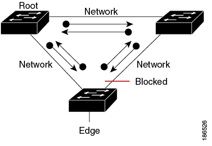
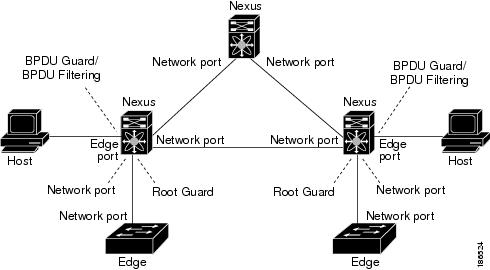
Applying STP Extension Features
We recommend that you configure the various STP extension features through your network as shown in this figure. Bridge Assurance is enabled on the entire network. You should enable either BPDU Guard or BPDU Filtering on the host interface.
PVST Simulation
MST interoperates with Rapid PVST+ with no need for user configuration. The PVST simulation feature enables this interoperability.
Note |
PVST simulation is enabled by default when you enable MST. By default, all interfaces on the device interoperate between MST and Rapid PVST+. |
However, you may want to control the connection between MST and Rapid PVST+ to protect against accidentally connecting an MST-enabled port to a port enabled to run Rapid PVST+. Because Rapid PVST+ is the default STP mode, you may encounter many Rapid PVST+ connections.
Disabling Rapid PVST+ simulation, which can be done per port or globally for the entire device, moves the MST-enabled port to the blocking state once it detects it is connected to a Rapid PVST+-enabled port. This port remains in the inconsistent state until the port stops receiving Rapid PVST+/SSTP BPDUs, and then the port resumes the normal STP transition process.
The root bridge for all STP instances must all be in either the MST region or the Rapid PVST+ side. If the root bridge for all STP instances are not on one side or the other, the software moves the port into a PVST simulation-inconsistent state.
Note |
We recommend that you put the root bridge for all STP instances in the MST region. |
High Availability for STP
The software supports high availability for STP. However, the statistics and timers are not restored when STP restarts. The timers start again and the statistics begin from 0.
Note |
See the Cisco Nexus 9000 Series NX-OS High Availability and Redundancy Guide, for complete information on high-availability features. |
 Feedback