Managing Virtual Machine Disaster Recovery

HX Disaster Recovery Overview

HyperFlex DR enables the protection of virtual machines from disaster by configuring the replication of running VMs between a pair of network connected clusters. Protected virtual machines running on one cluster replicate to the other cluster in the pair, and vice versa. The two paired clusters typically are located at a distance from each other, with each cluster serving as the disaster recovery site for virtual machines running on the other cluster.

Once protection is configured on a VM, the HX Data Platform periodically takes a Data Protection (DP) Snapshot of the running VM on the local cluster and replicates (copies) the DP snapshot to the paired remote cluster. In the event of a disaster at the local cluster, the most recently replicated snapshot of each protected VM can be recovered on the remote cluster. Each cluster that serves as a disaster recovery site for another cluster must be sized with adequate spare resources so that upon a disaster, it can run the newly recovered VMs in addition to its normal workload.


Note


Only the most recently replicated DP snapshot is retained on the destination cluster. Retaining additional DP snapshots is not supported.


Each VM is individually protected by assigning it protection attributes, including the replication interval (schedule). The shorter the replication interval, the fresher the replicated snapshot data is likely to be. DP snapshot intervals can range from once every 5 minutes to once every 24 hours.

A protection group is a group of VMs that have a common DP snapshot schedule , quiescence parameter value, and a common start time.

Setting up DP snapshots requires two existing clusters running a currently supported HX Data Platform Software Release. Both clusters must be on the same HX Data Platform version. Use HyperFlex Connect to complete the setup.

First, set up a local replication network for each cluster. Use HX Connect to provide a set of IP addresses to be used by local cluster nodes to replicate to the remote cluster. HX Connect creates VLANs through UCS Manager, for dedicated local replication network use.


Note


When this option is chosen in HX Connect, UCSM is configured only when both UCS Manager and fabric interconnect are associated with the HyperFlex cluster. When UCSM and FI are not present, you must enter the VLAN ID, and not select UCSM configuration in HX Connect.


The two clusters, and their corresponding existing relevant datastores must be explicitly paired. The pairing setup can be completed using HX Connect from one of the two clusters. This requires administrative credentials of the other cluster.

Virtual machines can be protected (or have their existing protection attributes modified) by using HX Connect at the cluster where they are currently active.

HX Connect can monitor the status of both incoming and outgoing replication activity on a cluster.

After a disaster, a protected VM can be recovered and run on the cluster that serves as the DP snapshot recovery site for that VM.

Replication and Disaster Recovery Requirements and Considerations


Note


Documentation for the N:1 DR for HyperFlex feature is located in the Intersight Help Center. The URL is https://www.intersight.com/help/saas/resources/replication_for_cisco_hyperFlex_clusters.


The following is a list of requirements and considerations when configuring virtual machine replication and performing disaster recovery of virtual machines:

  • Datastore Unmapped Behavior:

    HXDP Release 5.5(2a) and HXDP Release 6.0(x) and later: Unmap Other DRO datastore pair is supported when VMs are in an Active (protected) state on either of the site. VMs in a state other than Active (for example Recovered, Recovery_Failed, and Migrate_Failed) need to be moved to the Active (Protected) state for unmap other DRO datastore pair support.

  • Other DRO Datastore Delete Operations:

    The following guidelines apply to HXDP Release 5.5(2a) and HXDP Release 6.0(x) and later:

    • Delete operations are supported after upgrading to HXDP Release 6.0(1a).

    • Adding and editing schedules is not supported.

    • Datastore map and unmap is not supported if any DRO datastore unmap happens in parallel.

  • All Protected VMs Tab Usage: Do not to perform any DR actions available from All Protected VMs tab for SRM (OtherDRO) VMs.

  • Post HXDP Release 5.5(2a) and HXDP Release 6.0(x) and later Upgrade Action:

    When HyperFlex creates a SRA/SRM pair and protects VMs, SRM creates placeholder VMs on opposite site with same name to reserve the resources for the VM during migration and recovery. Cisco recommends that after upgrading to HXDP 6.0(1a) you delete the placeholder VMs. Failing to complete this action will result in DR workflows failing due to the VM with same name exists on the opposite site.


Caution


Operations via SRM: Even though VMs in SRM the environment are available for performing Planned Migration or Disaster Recovery. Cisco does not recommend users perform any kind of operations via SRM.


Admin Role Requirements

You can perform all replication and recovery tasks with administrator privileges on the local cluster. For tasks involving a remote cluster, both the local and remote user must have administrative privileges. You can configure administrative privileges with vCenter SSO on the respective clusters.

Networking Requirements

The replication network should be reliable and have a sustained minimum symmetric bandwidth that is the same as the bandwidth configured in the HyperFlex replication network. Do not share the network with any other applications or traffic on an uplink or downlink. Other requirements are as follows:

Table 1. Networking Requirements

Requirement

Description

Minimum and Recommended Bandwidth

The minimum supported bandwidth is 10 Mbps. Recommended bandwidth is half of the network link bandwidth available for replication. For example, if the network link bandwidth available is 100 Mbps, you should configure the replication bandwidth to be 50 Mbps.

Adaptive Bandwidth Control

Replication network variability may cause network bandwidth to vary and may include the introduction of network errors. Adaptive Bandwidth Control for replication will dynamically adjust the replication speed to scale down if errors are detected and scale up to the configured replication bandwidth limit when the errors are cleared.

Note

 
Adaptive Bandwidth Control is only in effect when the replication network bandwidth limit is enabled and configured as a non-zero number. Adaptive Bandwidth Control is disabled when the replication network bandwidth limit is not enabled (default). Enabling the replication bandwidth limit requires entering a bandwidth value in the range of 10 to 100,000 Mbit/s. It is recommended that the Administrator always configure a replication network bandwidth limit on both clusters, rather than use the default setting.

Measuring Available Replication Network Bandwidth

You can measure the bandwidth of a HyperFlex replication network between two sites by using the iperf utility. In preparation for using the iperf utility, configure the local replication networks on both HyperFlex clusters. After you have configured the local replication networks, you can then pair the HyperFlex clusters. Once you have paired the HyperFlex clusters, map one of the local datastores to a datastore on the remote HyperFlex cluster.

  • Deploy user VMs on both of the mapped datastores. Configure the user VMs with the same network and gateway as used by the respective HyperFlex replication network. The VM can be Ubuntu 16.04 to match the Linux distribution of the HyperFlex storage controller VMs.

    Note


    These VMs are only intended for the purpose of testing network bandwidth. After you have completed testing, you can delete them. There is no need to protect these VMs.

  • Install the iperf utility on both user VMs by running the command:

    apt get install iperf

  • Run the iperf server on the user VM deployed on site B by running the command:

    iperf -s

    Example Output:
          ------------------------------------------------------------
          Server listening on TCP port 5001
          TCP window size: 85.3 KByte (default)
          ------------------------------------------------------------
    

    Port 5001 should be open between the sites.

Measuring Available Replication Network Bandwidth (continued)

  • Run the following iperf command on the user VM on site A

    iperf -c <server ip> -i <interval in secs> -t <time in seconds>

    Example Output:
    Client connecting to a.b.c.d TCP port 5001
    TCP window size: 85.0 KByte (default)
    ------------------------------------------------------------
    local w.x.y.z port 47642 connected with a.b.c.d port 5001
    0.0-10.0 sec  44.8 MBytes  37.6 Mbits/sec
    10.0-20.0 sec    222 MBytes    187 Mbits/sec
    20.0-30.0 sec    312 MBytes    261 Mbits/sec
    30.0-40.0 sec    311 MBytes    261 Mbits/sec
    40.0-50.0 sec    312 MBytes    262 Mbits/sec
    50.0-60.0 sec    311 MBytes    261 Mbits/sec
    60.0-70.0 sec    312 MBytes    262 Mbits/sec
    70.0-80.0 sec    312 MBytes    262 Mbits/sec
    80.0-90.0 sec    311 MBytes    261 Mbits/sec
    90.0-100.0 sec   312 MBytes    262 Mbits/sec
    100.0-110.0 sec  311 MBytes    261 Mbits/sec
    

Note


Conduct testing in both directions, from the first paired cluster to the second paired cluster, and then from the second paired cluster to the first paired cluster. If this is a shared link with other applications, perform testing at the time the replication schedules are planned to run. When this link is shared, the available bandwidth for replication could be impacted and may result in congestion on the replication network which may result in packet drops. The HyperFlex replication engine monitors packet drops and throttles the replication traffic if required.

Maximum Latency

The maximum replication network latency supported is 75 ms between two paired clusters. There are conditions where it is possible that some replication jobs will encounter error conditions and fail. For example, this may occur when multiple replication jobs execute simultaneously with low network bandwidth and high latency. If this situation occurs, increase the replication network bandwidth, or reduce job concurrency by staggering the number of concurrent replication jobs. If this situation persists, VM unprotect operations may take longer than expected.

Measuring Replication Network Latency

You can measure the average replication network latency by running a ping command on any of the storage controller VMs on site A and site B.

From site A, execute ping command as performed in the following example:

ping -I eth2 "Repl IP of any ctlvm on site B" -c 100

Example Output:
100 packets transmitted, 100 received, 0% packet loss, time 101243ms
rtt min/avg/max/mdev = 0.112/0.152/0.275/0.031 ms

The average latency should be 75 ms or less.

Note


Execute the ping command in both directions, from site A to site B, and from site B to site A.

Network Ports

The comprehensive list of ports required for HyperFlex component communication is located in appendix A of the HX Data Platform Security Hardening Guide. The port/protocl requirements (as of Version 4.5.2a rev 3 dated September 2021) for HyperFlex replication are: ICMP, TCP: 9338, 9339, 3049, 4049, 4059, 9098, 8889, and 9350.

Testing Network Ports

Internal to the HyperFlex cluster, firewall entries are made on the source and destination storage controller VMs during the site pairing operation to allow the HX data platform access to the systems bi-directionally. You need to allow this traffic on WAN routers for each HX node replication IP address and management CIP address.

When you configure the local replication network on a HyperFlex cluster, you can manually perform a Test Local Replication Network action to test connectivity across the replication IP addresses of each storage controller VM on the local cluster. This test includes port connectivity and firewall checks. When the two clusters have been paired, you can manually perform a Test Remote Replication Network action to test connectivity between each local storage controller VM and each remote storage controller VM. Port connectivity and firewall checks are performed.

You can also use the Linux “netcat” utility as an additional option to check port connectivity.

Network Loss

Reliable transmission of data enables replication between two paired clusters to function optimally. Packet loss in data transmission between two paired clusters may degrade replication performance.

Diagnosing Dropped Packets

There are two cases where packet loss may occur - network congestion and transient network device errors.

If dropped packets occur on a replication network due to network congestion the HyperFlex cluster replication engine automatically throttles back replication bandwidth. Throttling replication network bandwidth reduces network congestion and results in the reduction of dropped packets. In extreme cases, replication bandwidth throttling may result in replication jobs taking longer to complete than anticipated.

Dropped packets that occur on a replication network due to transient network device errors may cause replication failures that occur randomly or at specific times of the day.

Dropped packets are not reported in the HX Connect user interface.

Occurrences of packet drop are logged in the HyperFlex storage controller logs. Users that experience noticeable replication job elongation or other failures can contact support for further assistance.

Cluster Requirements

When configuring virtual machine replication and performing disaster recovery of virtual machines, please ensure that the following cluster requirements are met:

Storage Space Requirements

Ensure that there is sufficient space on both clusters to accommodate the retention and processing of replicated DP snapshots. Each protected VM will result in the creation and subsequent replication of a DP snapshot based on the configured schedule interval. The most recent successfully replicated DP snapshot is retained on the destination HyperFlex cluster. Note that for every protected VM, there is a maximum of two DP snapshots present on the source cluster and two DP snapshots present on the destination cluster. This approach facilitates efficient difference-based replication and also assures that the most recent successfully replicated DP snapshot is available for recovery in the event that a newer DP snapshot fails to successfully complete the replication process. Although storage capacity reduction methods are applied, including deduplication and compression, each replicated virtual machine consumes some storage space.

  • Space Consumed by Protected VMs with Redolog Snapshots—When protecting a VM that also has VMware redolog snapshots, the entire content of the VM is replicated. The entire content includes the VM as well as any retained VMware redolog snapshot(s). This results in increased storage space utilization on both of the paired HyperFlex clusters. When a greater number of redolog snapshots are retained, storage space consumption will also increase.

  • Space Consumed by Protected VMs with HX Native Snapshots—When protecting a VM that also has HX native snapshots, only the latest VM data is replicated. Retained HX native snapshot data is not replicated. Typically, there is no need to account for space consumed by HX native snapshots on a replication destination HyperFlex cluster.

  • Space Consumed by Deleted VMs—Deleting a protected VM will not cause space to be reclaimed on the paired HyperFlex cluster datastore. The most recent successfully replicated DP snapshot will be retained to protect the VM from accidental deletion. In order to reclaim space consumed by protected VMs, the VMs must first be unprotected. When a VM is unprotected, the associated DP snapshots are deleted on both paired HyperFlex clusters.

  • Space Consumption Calculations—The amount of predicted space consumption in addition to the size of a protected VM can be expressed as:

    VM change rate times the number of DP snapshots retained

    The number of DP snapshots retained equals two (2). When a protected VM has VMware redolog snapshots the calculation will be skewed based on the number of retained snapshots.

    Space calculations should also consider that when a protected VM fails over or is migrated to the paired site, the calculations for the source and target can be reversed.

  • Difference Based Replication and Full Copy Replication—In a typical replication data protection lifecycle, a full copy of a protected VM is replicated in the form of a DP snapshot only once. This full copy replication job occurs when a VM is initially protected. After the initial replication job completes, subsequent replication jobs take advantage of efficient differencing-based technology to replicate only new and changed data.

    You cannot use difference-based technology in the following known corner cases:

    • A protected VM also has HX native snapshots. If the VM is reverted back to a retained HX native snapshot, the next scheduled protection job will perform a full copy replication job instead of a difference-based replication job. An additional full copy worth of space needs to be budgeted on both of the paired clusters.

    • A protected VM undergoes storage vMotion and is migrated to a different datastore. If the destination datastore is mapped to a datastore on the paired cluster, the next scheduled protection job will perform a full copy replication job instead of a difference-based replication job. An additional full copy worth of space needs to be budgeted on both of the paired clusters.

    • A protected VM has a DP snapshot that was taken in conjunction with a replication job. Subsequent to this, an initial HX native snapshot is created that also creates an HX Sentinel snapshot. The next scheduled protection job will perform a full copy replication job instead of a difference-based replication job. An additional full copy worth of space needs to be budgeted on both of the paired clusters.

    • When a protected VM DP snapshot is taken during an HX native snapshot workflow that created intermediate delta disks, the next scheduled protection job will perform a full copy replication job instead of a difference-based replication job. An additional full copy worth of space needs to be budgeted on both of the paired clusters.

    • When a new VMDK is added to an already protected VM, that specific VMDK will be full-copied once.

    Not having sufficient storage space on the remote cluster can cause the remote cluster to reach capacity usage maximums. If you note any Out of Space errors, refer to Handling Out of Space Errors for more information. Pause all replication schedules until space available on the cluster has been properly adjusted. Always ensure that cluster capacity consumption is below the space utilization warning threshold.

Supported Configurations

Supported configurations for native replication (NRDR 1:1) are: 2N/3N/4N Edge, FI, and DC-no-FI based clusters to 2N/3N/4N Edge, FI, and DC-no-FI based clusters, including stretched clusters, all managed through HX Connect.

HyperFlex hardware acceleration cards (PID: HX-PCIE-OFFLOAD-1) are supported with native replication beginning with HX 4.5(1a). You must enable HX Hardware Acceleration on both of the paired HyperFlex clusters.

Rebooting Nodes

Do not reboot any nodes in an HX cluster during a restore, replication, or recovery operation. Note that node reboot operation may occur as part of an upgrade process. You should pause the replication scheduler prior to an upgrade, and then resume it after the upgrade has completed.

Replication Network and Pairing Requirements

You must establish a replication network between HyperFlex clusters that uses replication for Data Protection (DP) snapshots. The replication network is created to isolate inter-cluster replication traffic from other traffic within each cluster and site. Please also consider the following:

Table 2. Replication Network and Pairing Requirements

Component

Description

HX Data Platform Version

Ensure that the HyperFlex clusters that are going to be paired for replication are running the same HX data platform software version. Note that the use of different HX data platform versions is only supported during HX data platform upgrades. In this scenario, one of the paired HyperFlex clusters may be running a different version of HX data platform software for the period of time until both of the paired clusters have been upgraded. Ensure that you upgrade both of the paired clusters to the same HX data platform version within the shortest possible time frame based on site specific constraints. Also note that a maximum of one major HX data platform release version difference is permitted when upgrading paired clusters. Additionally, the changing of any replication configuration parameter is not supported when the paired clusters are not both running the same HX data platform version during an upgrade.

Node Status

Ensure that all HyperFlex cluster nodes are online and fully operational prior to the creation of the local replication networks and performing the site pairing process.

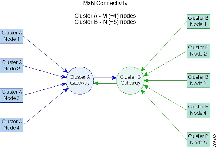
Node Communication Requirements

Requirements are as follows:

  • To support efficient replication, ensure that all M nodes of cluster A can communicate with all N nodes of cluster B, as illustrated in the M x N connectivity between clusters graphic.

  • To enable replication traffic between clusters to cross the site-boundary and traverse the internet, ensure that each node on Cluster A can communicate with each node on Cluster B across the site boundary and the internet.

  • Isolate the replication traffic from other traffic within the cluster and the data center.

For more information, see the graphic below.

M*N Connectivity Between Clusters

Node Failure

In the highly unlikely and rare event of a node failure, there may be an impact to replication. As an example, replication jobs in progress will stop if the node which has the replication CIP address enters an inoperative state. At the point in time when the replication CIP address is claimed by another node in the cluster, the replication job will automatically resume. Similarly, if a recovery job was running on the node with replication CIP address and the node failed, the job would fail. The replication CIP address would subsequently be claimed by another node in the cluster. Retry the operation upon noting the failure.

vCenter Recommendations

Ensure that each of the two paired HyperFlex clusters is managed by a unique vCenter instance. Also ensure that vCenter is deployed in a different fault domain for availability during disaster recovery scenarios.

Replication and Disaster Recovery Virtual Machine Considerations

The following are considerations for VMs:

Table 3. Virtual Machine Considerations

Consideration

Description

Thin Provisioning

Protected VMs are recovered with thin provisioned disks irrespective of how disks were specified in the originally protected VM.

VM Device Limitations

Do not protect VMs with connected ISO images or floppies as individually protected VMs, or within a protection group. You can set any configured CD or DVD drive to “Client Device” with the “Connected” state disabled. There is no need to delete the device from the VM configuration. If there is a need to temporarily mount an ISO image, you can unprotect the VM and then protect it again once you have set the CD or DVD drive to “Client Device” and then disconnected.

Protected Virtual Machine Scalability

Beginning with HX Release 4.5(1a):

  • The sum of protected VMs on all nodes should not exceed the maximum limit of 2000 protected VMs per cluster in a single direction configuration or 1000 protected VMs in a bi-direction configuration.

  • The maximum number of VMs allowed in a protection group is 64.

  • A maximum of 100 protection groups are supported.

Non-HX Datastores

Periodical replication fails on a protected a VM with storage on a non-HX datastore. To avoid the failure, unprotect the VM or remove non-HX storage from the VM. Do not move protected VMs from HX datastores to non-HX datastores. If a VM is moved to a non-HX datastore through storage vMotion, unprotect the VM before using vMotion.

Templates

Templates are not supported with disaster recovery. Do not attempt to protect a template.

Recovery of Virtual Machines with Snapshots

When recovering a protected VM that has VMware redolog snapshots, the VM is recovered and all previous snapshots redolog snapshots are preserved.

Data Protection Snapshots

Replicated DP snapshots are stored on the mapped datastore on the paired cluster. You should not perform a manual deletion of DP snapshots as this is not supported. Deleting snapshot directories or individual files will compromise HX data protection and disaster recovery.

Note


To avoid deleting DP snapshots manually, it is important to remember that VMware does not restrict operations on datastores by the administrative user. In any VMware environment, datastores are accessed by an administrative user via the vCenter browser or by logging into the ESXi host. Because of this, the snapshot directory and contents are browsable and accessible to administrators.

VMware SRM – Purposeful VM Deletion

Supported through HXDP Release 5.5(1a). Not supported in HXDP Release 5.5(2x).

If a VM is deleted from VMware vCenter and the VM is located in an “Other DRO” datastore pair, the SRM recovery plan for this datastore pair will fail during recovery. To avoid this scenario, first unprotect the VM using the following command on one of the HyperFlex storage controller VMs: stcli dp vm delete --vmid <VM_ID>

VMware SRM – Purposeful VM Deletion

Not supported in HXDP Release 5.5(2x) and later.

VM Naming

If a protected VM is renamed within vCenter, HyperFlex recovers at the previous name folder but registers the VM with the new name on the recovery side cluster. Following are some of the limitations to this situation:

  • VMware allows a VMDK located at any location to be attached to a VM. In such cases, HyperFlex recovers the VM inside the VM folder and not at a location mapped to the original location. Also, recovery can fail if the VMDK is explicitly referenced in the virtualmachine name.vmx file by its path. The data is recovered accurately but there could be problems with registering the VM to vCenter. Correct this error by updating the virtualmachine name.vmx file name with the new path.

  • If a VM is renamed and a VMDK is added subsequently, the new VMDK is created at [sourceDs] newVm/newVm.vmdk. HyperFlex recovers this VMDK with the earlier name. In such cases, recovery can fail if the VMDK is explicitly referenced in the virtualmachine name.vmx file by its path. The data is recovered accurately but there could be problems with registering the VM to the Virtual Center. Correct this error by updating the virtualmachine name.vmx file name with the new path.

HyperFlex Software Encryption

Software encryption must be enabled on clusters in both paired datastores to be able to protect VMs on encrypted datastores.

Storage Replication Adapter Overview


Note


The Storage Replication Adapter Feature is not supported in HXDP 5.5(2a) and later.


Storage Replication Adapter (SRA) for VMware vCenter Site Recovery Manager (SRM) is a storage vendor-specific plug-in for VMware vCenter server. The adapter enables communication between SRM and a storage controller at the Storage Virtual Machine (SVM) level as well as at the cluster level configuration. The adapter interacts with the SVM to discover replicated datastores.

For more information on installation and configuration of SRM, refer the following links as per the SRM release version:

You must install an appropriate SRA on the Site Recovery Manager Server hosts at both the protected and recovery sites. If you use more than one type of storage array, you must install the SRA for each type of array on both of the Site Recovery Manager Server hosts.

Before installing an SRA, ensure that SRM and JDK 8 or above version are installed on Windows machines at the protected and recovery sites.

To install an SRA, do the following:

  1. Download SRA from the VMware site.

    In the https://my.vmware.com/web/vmware/downloads page, locate VMware Site Recovery Manager and click Download Product. Click Drivers & Tools, expand Storage Replication Adapters, and click Go to Downloads.

  2. Copy the Windows installer of SRA to SRM Windows machines at both the protected and recovery sites.

  3. Double-click the installer.

  4. Click Next on the Welcome page of the installer.

  5. Accept the EULA and click Next.

  6. Click Finish.


Note


The SRA is installed within the SRM program folder:

C:\Program Files\VMware\VMware vCenter Site Recovery Manager\storage\sra

After SRA installation, refer the following guide as per the SRM release version and do the SRM environment setup:

After configuration, SRM works with SRA to discover arrays and replicated and exported datastores, and to fail over or test failover datastores.

SRA enables SRM to execute the following workflows:

  • Discovery of replicated storage

  • Non-disruptive failover test recovery using a writable copy of replicated data

  • Emergency or planned failover recovery

  • Reverse replication after failover as part of failback

  • Restore replication after failover as part of a production test

Data Protection Terms

Interval―Part of the replication schedule configuration, used to enforce how often the protected VMs DP snapshot must be taken and copied to the target cluster.

Local cluster―The cluster you are currently logged into through HX Connect, in a VM replication cluster pair. From the local cluster, you can configure replication protection for locally resident VMs. The VMs are then replicated to the paired remote cluster.

Migration―A routine system maintenance and management task where a recent replication DP snapshot copy of the VM becomes the working VM. The replication pair of source and target cluster do not change.

Primary cluster―An alternative name for the source cluster in VM disaster recovery.

Protected virtual machine― A VM that has replication configured. The protected VMs reside in a datastore on the local cluster of a replication pair. Protected VMs have a replication schedule configured either individually or by inclusion in a protection group.

Protection group―A means to apply the same replication configuration to a group of VMs.

Recovery process―The manual process to recover protected VMs in the event the source cluster fails or a disaster occurs.

Recovery test―A maintenance task that ensures the recovery process will be successful in the event of a disaster.

Remote cluster―One of a VM replication cluster pair. The remote cluster receives the replication snapshots from the Protected VMs in the local cluster.

Replication pair―Two clusters that together provide a remote cluster location for storing the replicated DP snapshots of local cluster VMs.

Clusters in a replication pair can be both a remote and local cluster. Both clusters in a replication pair can have resident VMs. Each cluster is local to its resident VMs. Each cluster is remote to the VMs that reside on the paired local cluster.

DP snapshot―Part of the replication protection mechanism. A type of snapshot taken of a protected VM, which is replicated from the local cluster to the remote cluster.

Secondary cluster―An alternative name for the target cluster in VM disaster recovery.

Source cluster―One of a VM replication cluster pair. The source cluster is where the protected VMs reside.

Target cluster―One of a VM replication cluster pair. The target cluster receives the replicated DP snapshots from the VMs of the source cluster. The target cluster is used to recover the VMs in the event of a disaster on the source cluster.

Best Practices for Data Protection and Disaster Recovery

The requirement for an effective data protection and disaster recovery strategy based on the environment being protected cannot be overstated. The solution should be designed and deployed to meet or exceed the business requirements for both Recovery Point Objectives (RPO) and Recovery Time Objectives (RTO) of the production VMs. The following are some of the points that must be considered when designing this strategy:

  • The number of Service Level Agreements (SLA) necessary to comply with various categories of production workloads that may include mission critical, business critical, and important VMs.

  • Detailed constructs of each SLA that may include RPO, RTO, the number or recovery points retained, requirements for off-site copies of data, and any requirements for storing backup copies on different media types. There may be additional requirements that include the ability to recover to a different environment such as a different location, different hypervisor or different private/public cloud.

  • An ongoing testing strategy for each SLA which serves to prove that the solution meets the business requirements it was designed for.

Note that backups and backup copies must be stored external to the HyperFlex cluster being protected. For example, backups performed to protect VMs on a HyperFlex cluster should not be saved to a backup repository or a disk library that is hosted on the same HyperFlex cluster.

The built-in HyperFlex data protection capabilities are generalized into the following categories:

  • Data Replication Factor—Refers to the number of redundant copies of data within a HyperFlex cluster. A data replication factor of 2 or 3 can be configured during data platform installation and cannot be changed. The data replication factor benefit is that it contributes to the number of cluster tolerated failures. See the section titled, HX Data Platform Cluster Tolerated Failures for additional information about the data replication factor.


    Note


    Data Replication Factor alone may not fulfill requirements for recovery in the highly unlikely event of a cluster failure, or an extended site outage. Also, the data replication factor does not facilitate point-in-time recovery, retention of multiple recovery points, or creation of point-in-time copies of data external to the cluster.


  • HX Native Snapshots—Operates on an individual VM basis and enables saving versions of a VM over time. A maximum of 31 total snapshots, including the HX SENTINEL snapshot, can be retained.


    Note


    HX native snapshots alone may not fulfill requirements for recovery in the unlikely event of a cluster failure, or an extended site outage. Also, HX native snapshots do not facilitate the ability to create point-in-time copies of data external to the cluster. More importantly, unintentional deletion of a VM also deletes any HX native snapshots associated with the deleted VM.


  • Asynchronous Replication—Also known as The HX Data Platform disaster recovery feature, it enables protection of virtual machines by replicating virtual machine DP snapshots between a pair of network connected HyperFlex clusters. Protected virtual machines running on one cluster replicate to the other cluster in the pair, and vice versa. The two paired clusters typically are located at a distance from each other, with each cluster serving as the disaster recovery site for virtual machines running on the other cluster.


    Note


    Asynchronous Replication alone may not fulfill requirements for recovery when multiple point-in-time copies need to be retained on the remote cluster. Only the most recent snapshot replica for a given VM is retained on the remote cluster. Also, asynchronous replication does not facilitate the ability to create point-in-time copies of data external to either cluster.


It is recommended to first understand the unique business requirements of the environment and then deploy a comprehensive data protection and disaster recovery solution to meet or exceed those requirements.

Protecting Virtual Machines Overview

To protect a virtual machine (VM), specify the following protection attributes:

  • Replication interval, at which DP snapshots are created for replication.

  • A start time (within the next 24 hours), which specifies the first-time replication is attempted for that VM.

  • Specify if the DP snapshot should be taken with the VM quiesced or not. Proper use of the quiesce option requires that VMware Tools are installed on the VM or VMs being protected.

  • VMware Guest Tool for quiesce snapshot in Disaster Recovery is supported. Install the most recent VMware Guest Tool Service or verify that the existing service is current.


    Note


    Using third-party guest tool (open-vm-tools) usage is allowed.


Protection attributes can be created and assigned to protection groups. To assign those protection attributes to VMs, they can be added to a protection group.

For example, there are three different SLAs: gold, silver, and bronze. Set up a protection group for each SLA, with replication intervals such as 5 or 15 minutes for gold, 4 hours for silver, and 24 hours for bronze. Most VMs can be protected by simply adding them to one of the three already created protection groups.

To protect VMs, you can choose from the following methods:


Note


When you select multiple VMs, you must add them to a protection group.


  • Independently―Select one VM and configure protection. Set the replication schedule and the VMware quiesce option for the specific VM. Changes to the replication settings will only affect the independently protected VM. The VM is not included in a protection group.

  • Existing protection group―Select one or more VMs and add them to an existing protection group. The schedule and VMware quiesce option settings are applied to all of the VMs in the protection group. If the protection group settings are changed, the changes are applied to all of the VMs in the protection group.

  • New protection group―Select two or more VMs and choose to create a new protection group. Define the protection group name, schedule, and VMware quiesce option settings. These settings are applied to all the VMs in the protection group. If the protection group settings are changed, the changes are applied to all of the VMs in the protection group.

Data Protection Workflow

To protect VMs and their data using DP snapshots and replication, perform the following steps:

  • Configure two clusters and pair them with each other, to support the replication network activity.

  • Assign a replication schedule to the VMs to set the frequency (interval) for creating DP snapshots on the source cluster and replicate them to the target cluster. Replication schedules can be assigned to individual VMs and to protection groups.

Replication Workflow

  1. Install HX Data Platform, create two clusters.

  2. Create at least one datastore on each cluster.

  3. Log into HX Connect.

  4. Before creating the replication network, verify the IP addresses, subnet mask, VLAN, gateway, and IP range to be used for the replication network. After the replication network is created, validate connectivity within the cluster over the replication network.

  5. The default value of MTU is 1500. If the HyperFlex cluster uses OTV or other tunneling mechanisms, ensure choosing an MTU value which will work for inter-site or inter-cluster connectivity. Starting with Cisco HyperFlex Release 5.0(2a) the MTU field is editable.

  6. Configure cluster replication network on each cluster. The replication network information is unique to each cluster.

    Specify the subnet, gateway, range of IP addresses, bandwidth limit for dedicated use by the replication network. HX Data Platform configures a VLAN through UCS Manager for both clusters.

  7. An intra-cluster network test is performed to validate connectivity between the nodes in the cluster, after the replication network is configured. If the intra-cluster network test fails, the replication network configuration is rolled back. Reconfigure the replication network after resolving any issues.

  8. Before creating the replication pair, ensure that you have updated the corporate network to support this pairing.

  9. Create a replication pair from one cluster to the other, connecting the two clusters. After the replication pair is created, a test of the inter-cluster pair network is performed to validate bidirectional connectivity between the clusters. Set the datastore mapping(s) from both clusters.

  10. Optionally, you can create protection groups.

    • Set the schedule. Each protection group must have one schedule.

    • Create multiple protection groups if you want to have various replication intervals (schedules) for different VMs. A VM can only belong to one protection group.

  11. Select VMs to protect, as individual virtual machines or VMs assigned to protection groups.

  12. Set protection, do the following:

    1. Select one or more VMs. Click Protect.

    2. From the Protect VM wizard, the options are:

      • Protect a single VM with an existing protection group.

      • Protect a single VM independently.

        Set the schedule.

      • Protect multiple VMs with an existing protection group.

      • Protect multiple VMs with a new protection group.

        Create new protection group and set schedule.

Configuring the Replication Network in HX Connect

Before a replication pair can be configured, the replication network has to be configured on both the local and remote cluster. Complete the configuration on the local cluster, then log into the remote cluster and complete the configuration there.

Before you begin

Ensure that the following prerequisites are met, before configuring the replication network:

  • A minimum of N + 1 IP addresses is required, where N is the number of converged nodes. An IP subnet spanning these new IP addresses, the gateway, and VLAN associated with this subnet is also required.

  • To accommodate future cluster expansion, ensure that there are sufficient IP addresses in the subnet provided, for later use. Any new nodes in the expanded cluster would also need to be assigned IP addresses for replication. The subnet provided in the previous step should span the potentially new IP range as well.

  • Additional IP-pool ranges can be added to the network later, however IP-pools already configured in the replication network cannot be modified.

  • Make sure that the IP addresses to be used for the replication network are not already in use by other systems.

  • Before creating the replication network, verify IP addresses, Subnet, VLAN, and Gateway to be used for the replication network.

Procedure


Step 1

Log into HX Connect as a user with administrator privileges.

Step 2

Select Replication > Replication Configuration > Configure Network.

Note


You can only configure the replication network once. Once configured, you can edit the available IP addresses and the networking bandwidth.

Step 3

In the Configure Replication Network dialog box, under the VLAN Configuration tab, enter the network information.

UI Element Essential Information

Select an existing VLAN radio button

Click this radio button to add an existing VLAN.

If you manually configured a VLAN for use by the replication network through Cisco UCS Manager, enter that VLAN ID.

Create a new VLAN radio button

Click this radio button to create a new VLAN.

Note


If you are configuring replication network on edge cluster, do not use the Create VLAN option. Use the existing VLAN option and follow the same procedure.

VLAN ID field

Click the up or down arrows to select a number for the VLAN ID or type a number in the field.

This is separate from the HX Data Platform Management traffic network and Data traffic network.

Important

 
Be sure to use a different VLAN ID number for each HX Storage Cluster in the replication pair.

Replication is between two HX Storage clusters. Each HX Storage cluster requires a VLAN dedicated to the replication network.

For example, 3.

When a value is added, the default VLAN Name is updated to include the additional identifier. The VLAN ID value does not affect a manually entered VLAN name.

VLAN Name field

This field is automatically populated with a default VLAN name when the Create a new VLAN radio button is selected. The VLAN ID is concatenated to the name.

For Stretched Cluster, provide Cisco UCS Manager credentials for primary and secondary FIs (site A and site B).For normal cluster, provide Cisco UCS Manager credential for single FI.

UCS Manager host IP or FQDN field

Enter Cisco UCS Manager FQDN or IP address.

For example, 10.193.211.120.

Username field

Enter administrative username for Cisco UCS Manager.

Password field

Enter administrative password for Cisco UCS Manager.

Step 4

Click Next.

Step 5

In the IP & Bandwidth Configuration tab, set the network parameters and the replication bandwidth.

UI Element Essential Information

Subnet field

Enter the subnet for use by the replication network in network prefix notation. The subnet is separate from the HX Data Platform Management traffic network and Data traffic network.
Format example:
x.x.x.x/<number of bits>
1.1.1.1/20

Gateway field

Enter the gateway IP address for use by the replication network. The gateway is separate from the HX Data Platform Management traffic network and Data traffic network.

For example, 1.2.3.4.

Note


The gateway IP address must be accessible even if the disaster recovery is being setup for a flat network.

IP Range field

Enter a range of IP addresses for use by the replication network.

  • The minimum number of IP addresses required is the number of nodes in your HX Storage Cluster plus one more.

    For example, if you have a 4 node HX Storage Cluster, enter a range of at least 5 IP addresses.

  • The from value must be lower than the to value.

    For example, From 10.10.10.20 To 10.10.10.30.

  • If you plan to add nodes to your cluster, include sufficient number of IP addresses to cover any additional nodes. You can add IP addresses at any time.

Note


The IP address range excludes compute-only nodes.

Add IP Range button

Click to add the range of IP addresses entered in IP Range From and To fields.

Set Replication Bandwidth Limit check box

Click the check box to enable setting the replication bandwidth limit. Enter the maximum network bandwidth that the replication network is allowed to consume for inbound and outbound traffic. This a value in the range of 10 to 100,000 Mbps.

Failure to enable replication bandwidth limiting disables Adaptive Bandwidth Control. This is not recommended as replication network variability may cause bandwidth-related replication errors.

The replication bandwidth is used to copy replication snapshots from this local HX Storage Cluster to the paired remote HX Storage Cluster.

Note

 
  • At lower bandwidth (typically, lesser than 50 Mbps), the replications of multiple VMs may exit without executing the replication process due to high data transfer rate. To overcome this issue, either increase the bandwidth or stagger VM replication schedule so that VMs do not replicate in the same window.

  • The bandwidth setting must be close to the link speed. The bandwidth setting for the clusters in the pair must be same.

  • The set bandwidth is applicable only for the incoming and outgoing traffic of the cluster to which the bandwidth is set to. For example, setting the bandwidth limit as 100Mb means that the 100Mb is set for incoming traffic and 100Mb is set for outgoing traffic.

  • The set bandwidth limit must not exceed the physical bandwidth.

  • The bandwidth configured must be same on both sites of the disaster recovery environment.

  • The allowed low bandwidth is 10Mb and the maximum latency supported with 10Mb is 75ms. If the initial replication of VMs fails due to lossy network or unstable HX clusters, the VM replication will be initiated again in the next schedule as a fresh replication job. In this case, you have to size the schedule accordingly to protect VMs.

Set non-default MTU check box

Default MTU value is 1500.

Select the check box to set a custom MTU size for the replication network. MTU can be set in the range 1024 to 1500.

Note

 
  • Use the same MTU value on both of the paired HX clusters.

  • Starting with HXDP Release 5.0(2a) and later, you can edit the MTU value after configuring the cluster. With older versions of HXDP, the existing replication network configuration will need to be removed. The replication network can then be configured with the correct MTU value.

Note


When you use an existing VLAN for replication network, the replication network configuration fails. You must add the self-created replication VLAN to the management vNIC templates in Cisco UCS Manager.

Step 6

Click Next.

Step 7

In the Test Configuration tab, check the replication network configuration.

Step 8

Click Configure.


What to do next

  • Be sure to configure the replication network on both HX Storage clusters for the replication pair.

  • After the replication network is created on the cluster, each converged node on the cluster would be configured with an IP address on the eth2 interface.

  • Check for duplicate IP assignment using 'arping'.

    For example:arping -D -b -c2 -I ethX $replicationIP` (replace ethX and $replicationIP with actual values).

    If there is a duplicate IP assignment, it is necessary to remove the replication network assignments.

Test Local Replication Network

To perform an intra-cluster replication network test, do the following:

Procedure

Step 1

Log into HX Connect.

  1. Enter the HX Storage Cluster management IP address in a browser. Navigate to https://<storage-cluster-management-ip>.

  2. Enter the administrative username and password.

  3. Click Login.

Step 2

In the Navigation pane, click Replication.

Step 3

From the Actions drop-down list, select Test Local Replication Network.

Step 4

Click Run Test.

Step 5

On the Activity page, you can view the progress of the Test Replication Network task.


Editing the Replication Network

When you expand a HX Cluster that has replication configured, ensure that you have sufficient IP addresses available for the replication network. The replication network requires dedicated IP addresses, one for every node in the cluster plus one more. For example, in a 3 node cluster, four IP addresses are required. If you are adding one more nodes to the cluster, a mininum of five IP addresses are required.

To edit the replication network to add IP addresses, perform the following tasks:

Procedure

Step 1

Log into HX Connect as administrator.

Step 2

In the Navigation pane, Select Replication.

Step 3

From the Actions drop-down list, select Edit Replication Network.

Step 4

In the Edit Network Configuration dialog box, you can edit the range of IPs to use and set the replication bandwidth limit for replication traffic. The replication network subnet and gateway are displayed for reference only and cannot be edited.

UI Element Essential Information

Replication Network Subnet field

Subnet for the replication network. The subnet that is configured for the replication network in network prefix notation. This value cannot be edited.
Format example:
p.q.r.s/<length> 
209.165.201.0/27

Gateway field

The gateway that is configured for the replication network. This is value cannot be edited.

IP Range field

Enter a range of IP addresses for use by the replication network.

  • The minimum number of IP addresses required is the number of nodes in the HX Storage Cluster plus one more.

    For example, if the HX Storage Cluster has 4 nodes, the IP Range must be at least 5 IP addresses.

  • The from value must be lower than the to value.

    For example, From 10.10.10.20 To 10.10.10.30.

  • You can add IP addresses at any time.

  • If you plan to add nodes to your cluster, include sufficient number of IP addresses to accommodate any additional nodes.

Note

 
The IP address range excludes compute-only nodes.

Add IP Range field

Click to add the range of IP addresses that are entered in IP Range From and To fields.

Set replication bandwidth limit check box (Optional)

Enter the maximum network bandwidth that the replication network is allowed to consume for outbound traffic.

Valid Range: 10 to 10,000. The default is unlimited, which sets the maximum network bandwidth to the total available replication network bandwidth.

The replication bandwidth is used to copy DP snapshots from the local HX Storage Cluster to the paired remote HX Storage Cluster.

Set non-default MTU check box

Default MTU value is 1500.

Select the check box to set a custom MTU size for the replication network. MTU can be set in the range 1024 to 1500.

Note

 
  • Use the same MTU value on both of the paired HX clusters.

  • Starting with HXDP Release 5.0(2a) and later, you can edit the MTU value after configuring the cluster. With older versions of HXDP, the existing replication network configuration will need to be removed. The replication network can then be configured with the correct MTU value.

Step 5

Click Save Changes.


The replication network is now updated. Any additional replication network IP addresses are available for new nodes should they be added to the storage cluster. Replication traffic adjusts to any changes made to the bandwidth limit.

Replication Pair Overview

Creating a replication cluster pair is a prerequisite for configuring VMs for replication. After two (2) HX clusters are paired, map the datastore on the remote cluster to a datastore on the local cluster.

Mapping datastore A on HX cluster 1 with a datastore B on HX cluster 2 enables any VM on HX cluster 1 that resides in datastore A and is configured for replication to be replicated to datastore B on HX cluster 2. Similarly, any VM on cluster 2 that resides in datastore B and is configured for replication to be replicated to datastore A on HX cluster 1.

Pairing is strictly 1-to-1. A cluster can be paired with no more than one other cluster.

Mapping is a strict 1-to-1 relationship. A datastore on a paired HX cluster can be mapped to no more than one datastore on the other HX cluster. Note that there can be multiple mapped datastores. For example, datastore A on HX cluster 1 mapped to datastore B on HX cluster 2, and datastore C on HX cluster1 mapped to datastore D on HX cluster 2.

Creating a Replication Pair

The replication pair defines the two halves of the protection network. The HX cluster you are logged into is the local cluster, the first half of the pair. Through this dialog, you identify another HX cluster, the second half of the pair, the remote cluster. After the replication pair is configured, and at least one pair of datastores have been mapped, you can begin protecting virtual machines. See the Virtual Machines tab. Below are the prerequisites and steps to create a replication pair.


Note


When pairing HX clusters, if you get the error: Check your cluster status or logs for possible solutions appears, check if the pairing is successful by running the following command:

stcli dp peer list

If the pairing is not successful, check the logs for solutions.


Before you begin
  • Create a datastore on both the local and the remote cluster.

  • Create an encrypted datastore on the remote cluster to protect the encrypted datastore on local site.


    Note


    Software encryption must be enabled on clusters in both paired datastores to be able to protect VMs on encrypted datastores.


  • Configure the replication network.

Procedure

Step 1

From HX Connect, log into either the local or remote HX cluster as a user with administrator privileges and do one of the following:

  1. Select Replication > Pair Cluster if you are doing cluster pairing for the first time.

  2. Select Replication > Create Replication Pair.

    The Create Replication Pair option is enabled only when you delete an existing replication pair after unprotecting all the VMs and removing all the dependencies.

Step 2

Enter a Name for the replication pair and click Next.

Enter a name for the replication pairing between two HX Storage clusters. This name is set for both the local and remote cluster. The name cannot be changed.

Step 3

Enter the Remote Connection identification and click Pair.

UI Element Essential Information

Management IP or FQDN field

Enter the cluster IP address or fully qualified domain name (FQDN) for the management network on the remote . For example: 10.10.10.10.

User Name and Password fields

Enter vCenter single sign-on or cluster specific administrator credentials for the remote HX cluster.

HX Data Platform verifies the remote HX cluster and assigns the replication pair name.

Once the Test Cluster Pair job is successful, you can proceed to the next step. On the Activity page, you can view the progress of the Test Cluster Pair job.

Note


Virtual machines to be protected must reside on one of the datastores in the replication pair.

Step 4

Click Next.

The Create New Replication Pair dialog box appears.

Step 5

To protect VMs using the HX Data Platform disaster recovery feature, click Native Protection and do the following:

  1. The Local Datastore column displays a list of the configured datastores on the local HX Storage cluster. Map one local datastore to one remote datastore.

  2. From the Remote Datastore pull-down menu, choose a datastore that needs to be paired with the local datastore.

  3. Click Map Datastores.

    If you chose to cancel the datastore mapping by clicking Cancel, you can map the datastores later using Map Datastores that appears under DATASTORE MAPPED in the Replication dashboard.

To change the local datastore selection:

  1. From the Remote Datastore pull-down menu, choose Do not map this datastore to remove the mapping from the current local datastore.

  2. From the Remote Datastore pull-down menu, choose a datastore to be paired with the local datastore.

Note

 
  • The virtual machines to be protected must be on the datastores you select. Moving virtual machines from the configured datastores for the replication pair, also removes protection from the virtual machines.

  • Moving virtual machine to another paired datastore is supported. If the VMs are moved to unpaired datastore, the replication operation fails.

Note


Once a local datastore is mapped to a remote datastore, the corresponding local datastore will not appear under Other DRO Protection.

Step 6

To protect VMs using SRM through disaster recovery orchestrator (DRO), click Other DRO Protection and do the following:

  1. The Local Datastore column displays a list of the unpaired configured datastores on the local HX cluster. Map one local datastore to one remote datastore.

  2. From the Remote Datastore pull-down menu, choose a datastore that need to be paired with the local datastore.

  3. From the Direction pull-down menu, choose Incoming or Outgoing as the direction of VM movement for the mapped datastores.

  4. From the Protection Schedule pull-down menu, choose the schedule for protecting all the VMs in the datastore.

  5. Click Map Datastores.

    If you chose to cancel the datastore mapping by clicking Cancel, you can map the datastores later using Map Datastores that appears under DATASTORE MAPPED in the Replication dashboard.

Note


If a new VM is added to the protected datastore, the newly added VM is also get protected by Cisco HyperFlex.

Note


The replication pairs that are edited under Other DRO Protection, are exposed to SRM.


What to do next
To check the protection status of virtual machines, do one of the following:
  • Click Virtual Machines in HX Connect. This displays the list of the virtual machines on the local cluster along with the protection status. If the VM is protected by SRM, the status is displayed as Protected (by other DRO).


    Note


    In the Virtual Machine page, the status of the VMs protected by SRM is displayed as unprotected until the completion of first auto protect cycle. Until then, the user is not recommended to manually protect those VMs.


  • Click Replication in HX Connect.

  • Click Protection Group under the Local VMs tab to view the VMs protected within a protection group. Click Other DRO under the Local VMs to view the VMs protected by SRM.

  • Click Replication in HX Connect. Click Replication Activity to view the replication activity status of the protected VMs. If the VM is protected by SRM, the status is displayed as Protected (by other DRO).

Test Remote Replication Network

To test the pairing between clusters in a remote replication network, do the following:

Procedure

Step 1

Log into HX Connect.

  1. Enter the HX Storage Cluster management IP address in a browser. Navigate to https://<storage-cluster-management-ip>.

  2. Enter the administrative username and password.

  3. Click Login.

Step 2

In the Navigation pane, click Replication.

Step 3

From the Actions drop-down list, select Test Remote Replication Network.

Field

Description

MTU Test Value

Default MTU value is 1500. MTU can be set in the range 1024 to 1500.

Note

 
  • Starting with HXDP versions 5.0(2a) and later, you can edit the MTU value after configuring the cluster. With older versions of HXDP, the existing replication network configuration will need to be removed. The replication network can then be configured with the correct MTU value.

Step 4

Click Run Test.

Step 5

On the Activity page, you can view the progress of the Replication Pair Network Check task.


Editing a Mapped Datastore Replication Pair

Editing a replication pair is changing the datastores for the replication pair.


Note


Datastores with same encryption property can be mapped.


Procedure

Step 1

Log into HX Connect as an administrator.

Step 2

Select Replication > Replication Pairs.

Step 3

Select the replication pair that needs to be edited and click Edit.

The Edit Replication Pair dialog box appears.

Step 4

To protect VMs using the HX Data Platform disaster recovery feature, click Native Protection and do the following:

  1. The Local Datastore column displays a list of the configured datastores on the local HX Storage Cluster. Map one local datastore to one remote datastore.

  2. From the Remote Datastore pull-down menu, choose a datastore that needs to be paired with the local datastore.

  3. Click Map Datastores.

To change the local datastore selection:

  1. From the Remote Datastore pull-down menu, choose Do not map this datastore to remove the mapping from the current local datastore.

  2. From the Remote Datastore pull-down menu, choose a datastore to be paired with the local datastore.

Note


Once a local datastore is mapped to a remote datastore, the corresponding local datastore will not appear under Other DRO Protection.

Step 5

To protect VMs using SRM through disaster recovery orchestrator (DRO), click Other DRO Protection and do the following:

  1. The Local Datastore column displays a list of the unpaired configured datastores on the local HX cluster. Map one local datastore to one remote datastore.

  2. From the Remote Datastore pull-down menu, choose a datastore that need to be paired with the local datastore.

  3. From the Direction pull-down menu, choose Incoming or Outgoing as the direction of VM movement for the mapped datastores.

  4. From the Protection Schedule pull-down menu, choose the schedule for protecting all the VMs in the datastore.

  5. Click Map Datastores.

Note


New VMs added to the protected datastore are also protected.

Note


The replication pairs that are edited under Other DRO Protection, are exposed to SRM.


What to do next
To check the protection status of virtual machines, do one of the following:
  • Click Virtual Machines in HX Connect. This displays the list of the virtual machines on the local cluster along with the protection status. If the VM is protected by SRM, the status is displayed as Protected (by other DRO).


    Note


    In the Virtual Machine page, the status of the VMs protected by SRM is displayed as unprotected until the completion of first auto protect cycle. Until then, the user is not recommended to manually protect those VMs.


  • Click Replication in HX Connect.

  • Click Protection Group under the Local VMs tab to view the VMs protected within a protection group. Click Other DRO under the Local VMs to view the VMs protected by SRM.

  • Click Replication in HX Connect. Click Replication Activity to view the replication activity status of the protected VMs. If the VM is protected by SRM, the status is displayed as Protected (by other DRO).

Removing a Peer Cluster

The preferred method for removing a paring relation for any reason is via HxConnect. In the event that it's necessary to unpair the clusters using the stcli dp peer delete command. The stcli dp peer delete command is a 2-cluster operation and removes pairing from both clusters.

In a situation where Cluster A and B were paired, and cluster B is permanently down, or unavailable for an extended period of time, it may be necessary to remove the pairing relation on cluster A the proper solution is to use the stcli dp peer forget --pair-name on cluster A.

To remove a peer cluster using the stcli dp peer delete:

Procedure

Run the stcli dp peer delete on one of the clusters in a pair to ensure that the pairing relation is removed from both clusters in the pair.

When successful, both the clusters are available for fresh configuration of data protection.


Deleting a Replication Pair

Delete a replication pair on the local and remote clusters.

Select Replication > Replication Pairs > Delete.

Before you begin

On both the local and remote HX clusters, remove dependencies from the replication pair.

Log into the local and the remote HX storage cluster and perform the following:

  • Unprotect all virtual machines. Remove virtual machines from protection groups.

  • Remove protection groups. If the protection group does not have a VM, deleting protection group is not required.

Procedure

Step 1

Log into HX Connect as an administrator.

Step 2

Unmap the datastores in the replication pair.

  1. Select Replication > Replication Pairs > Edit.

    After the test cluster pair job is successful, you can proceed to the next step. You can view the progress of the Test Cluster Pair job on the Activity page.

  2. From the Edit Replication Pair dialog box, select Do not map this datastore from the Remote Datastore menu.

    UI Element Essential Information

    Local Datastore column

    List of the configured datastores on this cluster, the local HX clusters.

    Map one local datastore to one remote datastore.

    Note


    The lock/unlock icon next to the datastore name indicates whether the dateastore encryption is enable or disabled:

    • Locked icon: encryption enabled

    • Unlocked icon: encryption disabled

    If encrypted local datastores are selected then only encrypted remote datastore information is displayed.

    Remote Datastore column

    Pair the datastores between the HX clusters.

    1. To change the local datastore selection, remove the mapping to the current local datastore.

      From the pull-down menu in the Remote Datastore column, select Do not map this datastore.

    2. From the desired Local Datastore row, select a datastore from the Remote Datastore pull-down menu. This selects both the remote and local datastores in a single action.

  3. Ensure all the possible remote datastores are set to Do not map this datastore.

  4. Click Finish.

Step 3

Select Replication > Replication Pairs > Delete.

Step 4

Enter administrator credentials for the remote cluster and click Delete.

UI Element Essential Information

User Name field

Enter the administrator user name for the remote HX Storage Cluster.

Password field

Enter the administrator password for the remote HX Storage Cluster.


Creating a Protection Group

A protection group is a group of VMs with the same replication schedule and VMware Tools quiescence settings.

Protection groups are created on the HX cluster that the administrative user is logged on to. Protection groups provide protection to the VMs that are members of a given protection group. If protection groups have protected virtual machines that replicate to the remote cluster, they are listed in HX Connect.


Note


The administration of protection groups can only be performed from the local cluster where it was created.


Before you begin

  • Ensure that replication network and replication pair are configured.

  • Install the most recent VMware Guest Tool Service or verify that the existing service is current.

Procedure


Step 1

Log into HX Connect as an administrator.

Step 2

Select Replication > Protection Groups > Create Protection Group.

Step 3

Enter the information in the dialog fields.

UI Element Essential Information

Protection Group Name field

Enter a name for the new protection group for this HX cluster.

Protection groups are unique to each HX cluster. The name is referenced on the remote HX cluster, but not editable on the remote HX cluster. Multiple protection groups can be created on each HX cluster.

Protect virtual machines in this group every field

Select how often the virtual machines are to be replicated to the paired cluster.

The pull-down menu options are: 5 minutes, 15 minutes, 30 minutes, 1 hour, 90 minutes, 2 hours, 4 hours, 8 hours, 12 hours, and 24 hours. The default value is 1 hour.

Start protecting the virtual machines immediately radio button

Select this radio button if you want the first replication to start immediately after you add the first virtual machine to this protection group.

Start protecting the virtual machines at radio button

Select this radio button if you want to set a specific time for the first replication operation to start.

Before you start replication ensure:

  • At least one virtual machine is added to the protection group.

  • The scheduled start time is reached.

To specify the protection operation start time:

  1. Check the Start protecting the virtual machines at radio button.

  2. Click in the time field and select an hour and minute. Then click out of the field.

Cluster time zone and Current time on cluster are references to help you to choose the appropriate replication start time. Start time is based on the local cluster clock. For example:

10 hours, 3 minutes from now with Current time on cluster, 1:56:15PM, means that the first replication occurs at 11:59:00PM.

The hours, minutes from now states when the first replication will occur. This is updated when you change the time field setting.

Use VMware Tools to quiesce the virtual machine check box

Select this check box to take quiesced DP snapshots. Leaving the check box in an unchecked state will take crash consistent DP snapshots.

This only applies to virtual machines with VMware Tools installed.

Step 4

Click Create Protection Group.

HX Data Platform adds the new group to the Protection Groups tab. This protection group is available to protect virtual machines on this cluster.

Step 5

Click the Replication > Protection Groups to view or edit the new protection group.

If the number of VMs is zero (0), add virtual machines to the new protection group to apply the replication schedule configured in the protection group.


Quiescence Overview

Quiescence is a process of bringing the on-disk data of a physical or virtual computer into a state suitable for backups. This process might include operations such as flushing dirty buffers from the operating system's in-memory cache to disk or other higher-level application-specific tasks.

HX Data Protection (DP) snapshots can be created with the guest file system quiesced. The quiesce option is available when using Cisco HyperFlex Connect, the HyperFlex command line user interface (UI), and HX REST APIs. VMware tools should be installed in the guest VM when creating HX DP snapshots using the quiesce option. For information on VMware, go to the VMware Website for the following:

  • VMware Compatibility Guide.

  • VMware Tools Documentation

  • Virtual Machine Tools, Version, and Status.

  • VMware Guest Operating System Installation Guide

HXDP Software Release 5.0(2a) and earlier supports the following guest states:

  • guestToolsCurrent

  • guestToolsUnmanaged

When the quiesce data protection snapshot fails, the DataProtectionVmError occurs which prompts an HX event and an HX alarm.

Editing Protection Groups

Change the replication interval (schedule) for the virtual machines in the protection group. To edit the protection groups, perform the following steps:

Procedure

Step 1

Log into HX Connect as an administrator.

Step 2

Select Replication > Protection Groups > Edit Schedule.

Step 3

Edit the information in the dialog fields.

UI Element Essential Information

Protect virtual machines in this group every field

Use the pull-down list to select how often the virtual machines are to be replicated to the paired cluster.

List values are: 5 minutes, 15 minutes, 30 minutes, 1 hour, 90 minutes, 2 hours, 4 hours, 8 hours, 12 hours, and 24 hours.

Use VMware Tools to quiesce the virtual machine check box

Select the check box to take quiesced DP snapshots. The checkbox is unchecked by default; leaving the check box unchecked, takes crash consistent DP snapshots.

This only applies to virtual machines with VMware Tools installed.

Step 4

Click Save Changes to save the interval and VMware Tools quiescence settings for the protection group. View the Protection Groups tab to verify the interval frequency.


Deleting Protection Groups

Before you begin

Remove all virtual machines from the protection group.

Procedure

Step 1

Select Replication > Protection Groups > protection_group_name

Step 2

Click Delete. Click Delete in the verification pop-up.


Protecting Virtual Machines with an Existing Protection Group

This task describes how to protect multiple virtual machines using an existing protection group.

Using an Existing protection group―Select one or more virtual machines and add them to an existing protection group. The schedule and VMware quiesce option settings are applied to all the virtual machines in the protection group. When the protection group settings are changed, the changes are applied to all the virtual machines in the protection group.

Before you begin

Replication network and replication pair configured.

Create protection group prior to adding the virtual machines.

Procedure


Step 1

Log into HX Connect with administrator privileges and select Virtual Machines.

This lists the virtual machines on the local HX cluster.

Step 2

Select one (1) or more unprotected VMs from the list.

Click in the virtual machine row to select it. As you click a virtual machine row, the corresponding virtual machine check box is selected.

Step 3

Click Protect.

The Protect Virtual Machines wizard, Protection Group page is displayed.

Step 4

Click the radio button, Add to an existing protection group

UI Element Essential Information

Set the protection parameters table

Verify the selected virtual machine Name.

Use the Storage Provisioned and Storage Used to check for sufficient storage resource availability on the remote HX cluster.

Add to an existing protection group radio button

Select an existing protection group from the pull-down list.

The interval and schedule settings of the protection group are applied to the selected VM or VMs.

Create a new protection group radio button

Enter a name for the new protection group for this local cluster.

Protection groups are unique to each cluster. The name is referenced on theremote cluster, but not editable on the remote cluster. You can create multiple protection groups on each cluster.

Step 5

Select a protection group from the pull-down list and click Next.

Be sure the protection group you choose has the schedule interval desired.

The Protect Virtual Machines wizard, Summary page is displayed.

Step 6

Confirm the information in the Summary page and click Add to Protection Group.

The selected VM or VMs are added to the protection group. View theReplication or Virtual Machines pages to confirm that the VM oir VMs have been added to the protection group.


Protecting Virtual Machines with a New Protection Group

This task describes how to protect multiple virtual machines by creating a new protection group.

Using a New protection group―Select VMs and choose to create a new protection group. Define the protection group name, schedule, start time, and VMware quiesce option settings. These settings are applied to all the virtual machines in the protection group. When the protection group settings are changed, the changes are applied to all the virtual machines in the protection group.

Before you begin

Replication network and replication pair configured.

Procedure


Step 1

Log into HX Connect with administrator privileges and select Virtual Machines.

This lists the virtual machines on the local HX cluster.

Step 2

Select one or more unprotected VMs from the list.

Click in the virtual machine row to select it. As you click a virtual machine row, the corresponding virtual machine checkbox is selected.

Step 3

Click Protect.

The Protect Virtual Machines wizard, Protection Group page is displayed.

Step 4

Click the radio button, Create a new protection group, add a name for the protection group, and click Next.

The Protection Schedule Wizard Page wizard page is displayed.

Step 5

Complete the schedule and VMware quiesce option, as needed, and click Next.

UI Element

Essential Information

Protect virtual machines in this group every field

Select how often the virtual machines are to be replicated to the paired cluster. The default value is every 1 hour.

Start protecting the virtual machines immediately radio button

Select this radio button if you want the first replication to start immediately after you add the first virtual machine to this protection group.

Start protecting the virtual machines at radio button

Select this radio button if you want to set a specific time for the first replication to start. To start replication requires:

  • At least one virtual machine is added to the protection group.

  • The scheduled start time is reached.

To specify the protection operation start time:

  1. Check the Start protecting the virtual machines at radio button.

  2. Click in the time field and select an hour and minute. Then click out of the field.

    The hours, minutes from now states when the first replication will occur. This is updated when you change the time field setting.

Cluster time zone and Current time on cluster are references to help you to choose the appropriate replication start time. Start time is based on the local cluster clock. For example:

10 hours, 3 minutes from now with Current time on cluster, 1:56:15PM, means that the first replication occurs at 11:59:00PM.

Use VMware Tools to quiesce the virtual machine check box

Click the check box to take quiesced DP snapshots. An unchecked check box takes crash consistent DP snapshots. The check box is unchecked by default.

This only applies to virtual machines with VMware Tools installed.

The Protect Virtual Machines wizard, Summary page is displayed.

Step 6

Confirm the information in the Summary page and click Add to Protection Group.

Review the summary content to confirm the settings to apply to the selected virtual machines.

  • Name of the protection group

  • Number of virtual machines to protect

  • Names of virtual machines

  • Storage provisioned for each virtual machine

  • Storage used (consumed) by each virtual machine

The selected VM or VMs are added to the protection group. View the Replication or Virtual Machines pages to verify that the VM(s) have been added to the protection group.


Protecting Individual Virtual Machines

This task describes how to protect a virtual machine (VM).

  • Independently―Select one (1) VM and configure protection. Set the replication schedule and the VMware Tools quiesce option for the specific VM.

    Changes to the replication settings only affect the independently protected VM. The VM is not a member of a protection group.

  • Existing protection group―Select one or more VMs and add them to an existing protection group. The schedule and VMware Tools quiesce option settings are applied to all the VMs in the protection group. When the protection group settings are changed, the changes are applied to all VMs in the protection group.

Before you begin

Configure replication network and replication pair.

Procedure


Step 1

Log into HX Connect with administrator privileges and select Virtual Machines.

Step 2

Select one unprotected virtual machine from the list. Click in the virtual machine row to select it.

Click in the virtual machine row to select it. As you click a virtual machine row, the corresponding virtual machine check box is selected.

Step 3

Click Protect.

The Protect Virtual Machine dialog box is displayed.

Step 4

Complete the fields as needed.

UI Element Essential Information

Add to an existing protection group radio button

Select an existing protection group from the pull-down list.

The interval and schedule settings of the protection group are applied to this virtual machine.

No additional configuration is required, click Protect Virtual Machine.

Protect this virtual machine independently radio button

Enables the interval, schedule options, and VMware Tools quiescence option for defining protection for this VM.

Protect this virtual machine every field

Select from the pull-down list how often the virtual machines are to be replicated to the paired cluster.

The list values are: 5 minutes, 15 minutes, 30 minutes, 1 hour, 90 minutes, 2 hours, 4 hours, 8 hours, 12 hours, and 24 hours.

Start protecting the virtual machines immediately radio button

Select this radio button if you want the first replication to start immediately after you add the first virtual machine to this protection group.

Start protecting the virtual machines at radio button

Select this radio button if you want to set a specific time for the first replication to start. To start replication requires:

  • At least one VM is added to the protection group.

  • The scheduled start time is reached.

To specify the protection operation start time:

  1. Check the Start protecting the virtual machines at radio button.

  2. Click in the time field and select an hour and minute. Then click out of the field.

    The hours, minutes from now states when the first replication will occur. This is updated when you change the time field setting.

Cluster time zone and Current time on cluster are references to help you to choose the appropriate replication start time. Start time is based on the local cluster clock. For example:

10 hours, 3 minutes from now with Current time on cluster, 1:56:15PM, means that the first replication occurs at 11:59:00PM.

VMware Tools to quiesce the virtual machine check box

To take quiesced DP snapshots, check the check box. The unchecked check box takes crash consistent DP snapshots. The check box is unchecked by default.

This only applies to virtual machines with VMware Tools installed.

Step 5

Click Protect Virtual Machine.

The VM status is updated in the Virtual Machine and the Replication page. Notice on the Replication page, that no Protection Group is listed for any VMs protected as individual VMs.

Replication is now enabled for this VM.


Unprotecting Virtual Machines


Note


There is no need to unprotect VMs to pause replication for HX cluster activities. See Pausing Replication.


Procedure


Step 1

Log into HX Connect as an administrator.

Step 2

Select Virtual Machines.

Step 3

Select a protected virtual machine from the list. Click in the virtual machine row.

VMs can be unprotected one VM at a time.

Step 4

Click Unprotect and click to confirm.

The state changes for the virtual machine from protected to unprotected.


Disaster Recovery Overview

Disaster recovery is performed when the source site is not reachable and you want to failover the VMs and the protected groups to the target cluster. The process of recovery recovers the VM on the target cluster. Recovering virtual machines is restoring a most recent replication snapshot from the recovery (target) cluster.

Software encryption must be enabled on clusters in both paired datastores to be able to protect VMs on encrypted datastores.

Testing VM recovery—The ability to test recovery without breaking replication. It can bring up your VM workload on the target to verify the contents of the VM.

Recovering virtual machines—Restoring a most recent replication snapshot from the target (recovery) cluster. Once you start Recovery, all scheduled replication will be stopped.

Planned migration—Performing planned migration pauses the replication schedule, creates and replicates a DP snapshot, and recovers on the target. Ownership is switched from the source to the target, and resumes replication on the target that is now the new source

Disaster Recovery and Reprotect—Recovers the VM on the target, switches the ownership from the source to the target, and resumes replication on the target that is now the new source.

Protecting VMs after disaster—In the event of a disaster, you may lose the source site altogether. After the recovery is performed protect the recovered VMs to a newer cluster.

Configuring the Recovery Settings

The configuration of recovery settings allows defining global recovery parameters and mapping for resources across recovery sites. It is possible to configure the folder, network, or resource pool parameters to be used during recovery, test recovery and migrate operations. If the global recovery setting is not configured, explicitly mapping individual VMs at the time of recovery is required.

Procedure


Step 1

Log into HX Connect as administrator and do one of the following:

  1. If configuring recovery settings for the first time, select Replication > Configure.

  2. Select Replication and click Actions next to Recovery Settings. From the Actions drop-down list, choose Edit Recovery Settings.

Step 2

In the Recovery Settings dialog box, enter the following fields:

Field

Description

Virtual Machine Power State radio button

By default, the Off option is selected. The recovered VM is powered on as per the selected option.

Test Virtual Machine Name Prefix field

Enter a prefix that you want to add to the virtual machine after test recovery. The prefix helps to identify the type and context of the resources.

Notification Setting radio button

Choose Normal Mode to get a confirmation prompt with summary of configuration at the time of recovery, test recovery, or migration. Choose Silent Mode to not get a confirmation prompt. On choosing silent mode, a confirmation window appears with the description of default behavior of silent mode. If you agree to the default behavior of silent mode, click OK.

Resource Pool area

Map the resources in the protected site to the resources in the remote site for the recovery, test recovery, and migrate configuration.

Check the Same as Recovery Configuration check box to use the resource mapping of recovery configuration for the test recovery configuration.

Click Add Rule to add one more resource pool mapping. Click the delete icon to remove a rule. To edit a rule, delete the rule and add the updated rule as a new rule.

Folder area

Map the folders in the protected site to the folders in the remote site for the recovery, test recovery, and migrate configuration.

Check the Same as Recovery Configuration check box to use the folder mapping of recovery configuration for the test recovery configuration.

Click Add Rule to add one more folder mapping. Click the delete icon to remove a rule. To edit a rule, delete the rule and add the updated rule as a new rule.

Network area

Map the network in the protected site to the network in the remote site for the recovery, test recovery, and migrate configuration.

Check the Same as Recovery Configuration check box to use the network mapping of recovery configuration for the test recovery configuration.

Click Add Rule to add one more network mapping. Click the delete icon to remove a rule. To edit a rule, delete the rule and add the updated rule as a new rule.

Step 3

Click Save.

On successful saving of the recovery settings, the RECOVERY SETTINGS field on the Replication page displays one of the following status along with the notification setting mode:
  • Partially Configured—This status is displayed when you have not set the recovery mapping for any of the resources or if any of the configured mapping is invalid.

  • Configured—This status is displayed when all the recovery settings are configured and valid.

Note


The RECOVERY SETTINGS field shows the last validated result. Once a rule is created for recovery, there is no automatic periodic validation. However, a validation job can be executed to check the validity of the rules existing in the recovery settings

The validation job summary in the Activity page directs the user to check the Recovery Settings page to view the validation result.


After configuring the recovery settings, validation of the recovery settings can be performed by choosing Validate Recovery Settings from the Actions drop-down list. The successful initiation of the recovery setting validation message is displayed. The RECOVERY SETTINGS field displays the time stamp of last validation. To monitor the progress of validation, click the Activity tab. In the normal notification setting mode, during recovery, test recovery, or migration of a virtual machine, the configured recovery settings are displayed.

It is possible to view the recovery configurations and edit them as required by checking the Modify recovery configuration for current operation check box. But, the recovery settings changes are applicable only for the current operation and the changes will not be updated to the global recovery settings.

Compatibility for Disaster Recovery Operations

As previously stated in the Replication Network and Pairing Requirements section, the use of different HX data platform versions is only supported during HX data platform upgrades. During the period of time until both of the paired clusters have been upgraded, the changing of any replication configuration parameter is not supported. The test-recover, recover, re-protect, and planned migration operations are expected to function during the period of time until both of the paired clusters have been upgraded. In some cases, the use of the command line user interface may be required to complete the re-protect and planned migration operations.

Testing Virtual Machine Recovery

Testing VM recovery gives you the ability to test recovery without breaking replication. It can bring up your VM workload on the target to verify the contents of the VM.


Note


  • Testing recovery does not disrupt the running clusters. The intent is to verify, in the event of an actual disaster, that the VMs are recoverable.

  • Using the HX Connect user interface, to test VM recovery, you can run a maximum of 10 tasks in a sequence without waiting for the previously submitted task to complete.


Before you begin

Before you begin the test VM recovery process, ensure the following:

  • The target cluster is up and in good health.

  • The protected VMs completed a recent replication to the target cluster. These replicated VMs are stored as DP snapshots on the target clusters.


Important


Only one copy of the test recovered VM can be made at any point. If you need to have another test recovered VM, please delete the previously created test recovered VM.


To the test VM recovery process perform the following steps:

Procedure


Step 1

Log into HX Connect on the target cluster as administrator.

Step 2

Navigate to Replication > Remote VMs Tab > protected_vm.

Step 3

To test the recovery process, click the Test Recovery button.

Note


When configuring recovery settings, the following fields are auto-populated.

UI Element

Essential Information

Resource Pool drop-down list

Select a location for the test VM to be stored.

Folders drop-down list

Select a location for the test VM to be stored, for example:

  • Discovered Virtual Machine

  • HX Test Recovery

Power On/Off radio button

By default, the Power ON option is selected. The recovered VM is powered on or left off after it is created as per the selected option.

VM Name field

Enter a new name for the created test VM.

Test Networks radio button

Select which HX Storage Cluster network to use for transferring the data from the replication snapshot.

Network options for example:

  • Storage Controller Data Network

  • Storage Controller Management Network

  • Storage Controller Replication Network

  • VM Network

Map Networks radio button

Select to create a map between the source and the target cluster networks.

  • Source Network―Network name at the source side on which the VM is connected.

  • Target Network―Select target network from the drop-down list, where the VM has to be connected.

Step 4

Click Recover VM.

Step 5

For VMs that are part of a protection group, perform a test recovery on each VM in the group.

Step 6

Verify the contents of the recovered VM.


Recovering Virtual Machines

Recovering VMs is restoring a most recent replication snapshot from the target (recovery) cluster.


Attention


  • You may configure the folder, network, or resource pool parameters to be used during recovery, test recovery and migrate operations. If the global recovery setting is not configured, you will need to explicitly map individual VMs at the time of recovery.

  • Recover VM is not supported between different vSphere versions. If the Target is at a lower version vSphere environment and does not support the hardware version of a protected VM on the primary, VM test recovery and recovery may fail. Cisco recommends to test recover each protected VM to validate the support on the target site.

    Upgrade the target environment to enable recovery of protected VMs.

  • Cancelling a recovery process (rolling back) is not supported. Attempting to cancel a recovery process changes all VMs in an unprotected ‘ready to recovery’ state.

  • When running recovery on VMs, you may specify explicit network mapping when recovering the VMs to avoid unintentional network connections to recovered VMs.

    You can skip specifying network mapping in the following cases:

    • If the source VMs use vSphere Standard Switches and if all ESXi hosts on the recovery side have standard switch networks with the same name.

    • If the source VMs use vSphere Distributed Switch (vDS) port groups and if the recovery site has identically named vDS port groups.

  • If you want to specify network mapping, ensure that both the name and the type of the VM network matches between the source and the target.

  • When running recovery on virtual machines that are individually protected, or that are in different protection groups, the maximum number of concurrent recovery operations on a cluster is 20.


Before you begin

Ensure the following:

  • The target cluster is up and in good health.

  • The protected VMs completed a recent replication to the target cluster. Replicated VMs are stored as DP snapshots on the target clusters.

On the target cluster, perform the following to conduct disaster recovery.

Procedure


Step 1

Log into HX Connect as administrator.

Step 2

Select Replication > > Remote VMs tab > > protected_vm and click Recover.

Step 3

To recover the VM and build a new VM on the local cluster, click the Recover VM button.

Note


When you configure recovery settings, the following fields are auto-populated.

UI Element

Essential Information

Resource Pool drop-down list

Select a location for the new VM to be stored.

Folders drop-down list

Select a location for the new VM to be stored.

Power On/Off radio button

By default Power ON option is selected. The recovered VM is powered on or left off after it is created as per the selected option.

Map Networks

Select to create a map between the source and target cluster networks.

  • Source Network―Network name at the source side on which the VM is connected.

  • Target Network―Select target network from the drop-down list, where the VM has to be connected.

Network options for example:

  • Storage Controller Data Network

  • Storage Controller Management Network

  • Storage Controller Replication Network

  • VM Network

Step 4

Click Recover VM.

Step 5

Wait for the recovery to complete. View the recovered VM in the target vCenter.


Recovering Virtual Machines in Protection Groups

Procedure


Step 1

Select a protected-vm and click Recover.

All VMs will be moved from the protection group and the selected VMs will be recovered. Recovered VMs show protection status as Recovered and the remaining (protection group) VMs show protection status as Recovering. The protection group will go in Recovered state and is not reusable. You can delete it from the primary site.

Note


Clicking Recover for a VM in a group puts it in a Recovered state (actual recovery happened), while the rest of the VMs in the standalone list are in Ready for Recovery state.

The recovered VMs are displayed in the Standalone Protected VMs subpane.

Step 2

Recover the remaining virtual machines from the Standalone Protected VMs subpane, which were a part of the protection group. See Recovering Virtual Machines for more details.


Planned Migration

Performing a planned migration pauses the replication schedule, replicates the most recent copy, recovers on the target, switches the ownership from the source to the target, and resumes replication on the target that is now the new source.

To perform a planned migration, take the following steps:


Attention


This process cannot be rolled back.


Procedure


Step 1

Log into HX connect of the target cluster. The target cluster is where the replicated DP snapshots were copied to.

Step 2

On the target cluster, select Replication > Remote VMs Tab > protected_vm.

Step 3

Click Migrate.

Note

 
All the fields that are listed here are optional.

UI Element

Essential Information

Resource Pool drop-down list

Select a location for the new VM to be stored.

Folders drop-down list

Select a location for the new VM to be stored.

Power On/Off radio button

By default Power ON option is selected. The recovered VM is powered on or left off after it is created as per the selected option.

Map Networks

Select to create a map between the source and target cluster networks.

  • Source Network―Network name at the source side on which the VM is connected.

  • Target Network―Select target network from the drop-down list, where the VM has to be connected.

Network options for example:

  • Storage Controller Data Network

  • Storage Controller Management Network

  • Storage Controller Replication Network

  • VM Network

Step 4

Monitor the progress on the Activity page.


Low Bandwidth and Temporary Packet Loss - In the event VM migration operation fails with an error message that contains "THRIFT_EAGAIN (timed out)", retry the VM Migration. The timeout error is due to temporary network congestion caused by bandwidth saturation or underlying network packet loss.

Planned Migration for a Single vCenter Deployment

To perform a planned migration for a single vCenter deployment, take the following steps:


Attention


This process cannot be rolled back.


Procedure

Step 1

Using the Web CLI, run the following command to prepare for failover on the source:

# stcli dp vm prepareFailover --vmid <VMID>

Note


You can use the stcli dp vm list --brief command to determine the VMID of a protected VM.

The task ID is returned.

Step 2

Log into vSphere Web Client Navigator of the primary site and remove the VM from the primary site to unregister the VM.

Right-click on the virtual machine and select All vCenter Actions > Remove from Inventory.

Step 3

Log into HX Connect of the secondary site. Select Replication > Remote VMs Tab > protected_vm. Click Migrate.

Step 4

After the Migrate task has completed successfully, log into vSphere Web Client of the secondary site and manually register the VM.

  1. Log into vSphere Web Client Navigator. Select Configuration > Storage.

  2. Right-click on the appropriate datastore and click Browse Datastore.

    Navigate to the virtualmachine name.vmx file, right-click on the file and click Add to Inventory. Follow the wizard to manually register the VM.


Low Bandwidth and Temporary Packet Loss - In the event VM migration operation fails with an error message that contains "THRIFT_EAGAIN (timed out)", retry the VM Migration. The timeout error is due to temporary network congestion caused by bandwidth saturation or underlying network packet loss.

Migrating Virtual Machines in Protection Groups

Using the HX Connect user interface, to migrate VMs, you can run a maximum of 4 tasks in a sequence without waiting for the previously submitted task to complete.

Procedure


Step 1

Select a protected-vm and click Migrate.

All the VMs are now moved out from the protection group and are displayed in the Standalone Protected VMs subpane. Only the selected VM is recovered.

Step 2

Migrate the remaining virtual machines from the Standalone Protected VMs subpane, which were a part of the protection group. See Planned Migration for more details.


Disaster Recovery and Re-protect

Performing disaster recovery recovers the VM on the target, switches the ownership from the source to the target, and resumes replication on the target that is now the new source. Disaster recovery is typically done when disaster occurs, and when you want to reverse the direction of protection.


Attention


  • This process cannot be rolled back.

    1. Log into vSphere Web Client Navigator of the primary site and remove the VM from the primary site to unregister the VM.

      Right-click on the virtual machine and select All vCenter Actions > Remove from Inventory.

    2. Log into HX Connect of the secondary site. Select Replication > Remote VMs Tab > protected_vm. Click Recover.

    3. When the primary site comes back up, log into HX Connect of the secondary site. Select Replication > Remote VMs Tab > unprotected. Click Re-protect.

    4. After Re-protect has completed successfully, log into vSphere Web Client of the secondary site and manually register the VM.

      1. Log into vSphere Web Client Navigator. Select Configuration > Storage.

      2. Right-click on the appropriate data store and click Browse Datastore.

        Navigate to the virtualmachine name.vmx file, right-click on the file and click Add to Inventory. Follow the wizard to manually register the VM.
  • Using the HX Connect user interface, you can run a maximum of 5 re-protect tasks in a sequence without waiting for the previously submitted task to complete.


Procedure


Step 1

Log into HX connect of the source and the target. The target cluster is where the replicated DP snapshots were copied to. The source cluster is the cluster where the VMs reside.

Step 2

Select a VM from the remote VM list. Execute the Recover VM workflow on this cluster workflow.

Note


If both the target and source clusters are on the same vCenter, then unregister the VM on the source cluster. This ensures that vCenter no longer has a record of the VM and it stops managing the VM, but it retains the data for the VM.

Step 3

Select Replication > > Remote VMs tab > > unprotected and click Recover.

Step 4

To recover on the target VM and build a new VM on the local cluster, click the Recover VM button.

Complete the following fields in the Recover VM on this cluster dialog box.

UI Element

Essential Information

Resource Pool drop-down list

Select a location for the new VM to be stored.

Folders drop-down list

Select a location for the new VM to be stored.

Power On/Off radio button

By default the Power ON option is selected. The recovered VM is powered on or left off after it is created as per the selected option.

Map Networks

Select to create a map between the source and target cluster networks.

  • Source Network―Network name at the source side on which the VM is connected.

  • Target Network―Select target network from the drop-down list, where the VM has to be connected.

Network options for example:

  • Storage Controller Data Network

  • Storage Controller Management Network

  • Storage Controller Replication Network

  • VM Network

Step 5

Click Recover VM.

Step 6

On the target cluster, select Replication > Remote VMs Tab > unprotected.

Step 7

Click Re-protect.

Attention

 
  • If both the target cluster and source cluster are on the same vCenter, manually register the VM on the source cluster.

  • When the Re-protect task fails and in the HX Connect UI the Re-protect tab is not available, execute stcli reverseprotect to complete the Re-protect operation.

Protection status of the VM shows as Protected.

Step 8

After the original primary comes up, to migrate back to the primary do the following:

  1. On the target cluster, select Replication > Remote VMs Tab > unprotected.

  2. Click Migrate to unregister the target VM and transfer the VM ownership to the original primary.

    Protection status of the VM shows as Protected.

Protecting Virtual Machines After Disaster

In the event of a disaster, you may lose the source site altogether. After the recovery is performed, you may want to protect the recovered VMs to a newer cluster.

Important Usage Guideance: Starting with Cisco HyperFlex Release 5.0(2b) users should review the following use case before proceeding.

The stcli dp peer forget --pair-name operation is a single cluster operation and only affects the cluster where the command is executed. The stcli dp peer delete is a 2-cluster operation and removes pairing from both clusters.

In a situation where Cluster A and B were paired, and cluster B is permanently down, or unavailable for an extended period of time, it may be necessary to remove the pairing relation on cluster A the proper solution is to use the stcli dp peer forget --pair-name on cluster A.

Procedure


Step 1

Recover the Virtual Machines. Perform standalone recovery (Recovering VMs) or group recovery (Recovering VMs in protection groups). See Recovering Virtual Machines for more details.

Step 2

To clear the existing pairing, run the following command in the HX Connect WebCLI:

stcli dp peer forget --all

Now the cluster is no longer paired to the original source.

Step 3

Unprotect all the local and remote VMs. See Unprotecting Virtual Machines for more details.

Step 4

Use STCLI to clean-up the protection group data.

Remove Protection group (if any) 
stcli dp group list
stcli dp group delete --groupid <groupUUID>

Note


GroupUUID is the vmGroupEr.id from the group list command.

Group delete is not supported in HX connect for remote cluster. Use stcli.

Step 5

(Optional) If needed, use the stcli drnetwork cleanup command to change the DR network. For more information see the Cisco hyperFlex Data Platform CLI Guide for your release.

Step 6

Pair to the new cluster. See the Creating a Replication Pairsection for more details.

Step 7

Protect the virtual machines.


Removing Protection from an Auto-Protected Cluster VM

In the event that the vCLS vms are not showing in Virtual machines page, but still they are getting auto protected, you can perform the following steps to remove protection from the auto-protected cluster VM.

Before you begin

  • VSphere Cluster Services (vCLS) VM should not reside on Backup or DR/SRM datastores.

  • Do not place vCLS VMs on HX datastores that are intended for 1:1 DR or N:1 Backup functionality.

Procedure


Step 1

Unprotect the VM using the stcli dp vm delete <vmid> cli.

Step 2

Use VCenter to Storage VMotion the VM to a different datastore.


Replication Maintenance Overview

Replication, when configured, runs in the background according to defined schedules. Replication maintenance tasks include:

  • Testing recovery―Testing if the recovery methods are working. See Testing Virtual Machine Recovery for more details.

  • Pausing replication―When preparing to upgrade the HX cluster and replication is configured, replication activity must be paused.

    Use the stcli dp schedule pause command.

  • Resuming replication―After HX cluster maintenance activities are complete, resume the replication schedule.

    Use the stcli dp schedule resume command.

  • Migration―The option to shift VMs from one source cluster to the replication paired target cluster, making the target cluster the new source cluster for the migrated VMs.

The following image illustrates which configuration is used for Disaster Recovery on HyperFlex if you are deploying in an ACI setup on a broad scale:

Pausing Replication

Before performing a storfs or platform upgrade, if replication is configured replication activity must be paused.

Procedure


Step 1

Log into a Storage Controller VM.

Step 2

From the command line, run the stcli dp schedule pause command.

Step 3

Perform the upgrade task.

Step 4

Resume the replication schedule.


Resuming Replication

After successfully upgrading the HX Storage Cluster which had replication configured, do the following to resume the replication schedule.

Before you begin

Ensure that HX cluster replication is paused and that any maintenance or upgrade tasks are complete.

Procedure


Step 1

Log into a Storage Controller VM.

Step 2

From the command line, run the stcli dp schedule resume command.


The previously configured replication schedule for all the protected virtual machines begins.

Replication Page

Displays summary information and links to detailed information related to Replication Configuration, Local Protection, and Remote Protection.

Replication Configuration Ribbon

UI Element Essential Information

REPLICATION CONFIGURATION field

Displays the state of the replication network configuration.

  • Replication network not configured—The replication network has not been configured.

    Click Configure to begin.

  • Network configured—The replication network is configured.

    Click Edit to adjust replication network IP ranges or bandwidth limit.

BANDWIDTH LIMIT field

Displays the configured bandwidth allowed for transmitting incoming and outgoing replication data.

  • Blank—The replication network is not configure.

  • # Mbps—Configured setting in Mega bits per second (Mbps).

  • Maximum―The default setting. Allows the replication network to use the total available network bandwidth.

Click Edit to change the bandwidth limit.

Bandwidth chart

Displays the bandwidth being consumed for data being replicated between this HX Storage Cluster and the paired HX Storage Cluster. Vertical axis is bandwidth and horizontal axis is time.

For more details, see the Performance Page.

Actions drop-down list

Click to create or edit the replication network for this HX Storage Cluster and to test the replication network.

  • Test Local Replication Network—<define>

  • Edit Replication Network—Edit IP Range and set replication bandwidth limit.

Recovery Settings Ribbon

UI Element Essential Information

Cluster Pairing field

Displays the name of the cluster pair.

  • Click Pair Cluster that appears when cluster pairing is not done, to initiate cluster pairing.

  • Click Create Replication Pair to initiate cluster pairing. The Create Replication Pair option is displayed only when you delete an existing replication pair after unprotecting all the VMs and removing all the dependencies.

DATASTORE MAPPED field

Displays the number of mapped datastores.

  • Click Map Datastore Pairs that appears when datastore mapping is not done, to map one local datastore to one remote datastore.

RECOVERY SETTINGS field

Displays the state of the recovery settings configuration.

  • Click Configure that appears when recovery settings configuration is not done, to configure the recovery settings to return the network to a known working state during recovery or test recovery.

Actions drop-down list

Choose any one of the action to perform specific operation on replication network, recovery settings, and datastore mapping.

  • Test Remote Replication Network—To test the pairing between clusters in a remote replication network.

  • Validate Recovery Settings—To validate the configured recovery settings.

  • Edit Recovery Settings—To edit the recovery settings configuration.

  • Edit Datastore Mapping—To edit the mapping between local and remote datastores.

Local/Remote Protection Summary Ribbons

UI Element Essential Information

VMs field

Displays the total number of virtual machines configured for protection on the Local cluster or on the Remote cluster. Displays the details for individual virtual machines and virtual machines in protection groups.

Click the field to display the list of protected virtual machines in the Local VMs or Remote VMs tab.

Protected field

Displays the total number of virtual machines that have a replication snapshot created.

Click the field to display the list of protected virtual machines in the Local VMs or Remote VMs tab.

Exceeds Interval field

Displays the number of replications that took longer than the configured interval to complete.

For example, if a virtual machine has an interval of every 15 minutes and replicating its snapshot from the local to the remote cluster took 20 minutes, the replication exceeded the interval.

Click the field to display the list of virtual machines with exceeded interval in the Local VMs or Remote VMs tab.

Current Replication Failures field

Displays the current number of replications that did not complete.

Click the field to display the list of virtual machines with failed replication in the Local VMs or Remote VMs tab.

Protection Groups field

Displays the total number of protection groups configured for this HX Storage Cluster.

Click the field to display the list of protection groups and their associated VMs in the Protection Groups section under the Local VMs or Remote VMs tab.

The Replication page table provides four tabs: Local VMs, Remote VMs, Replication Activity, and Replication Pairs. Each of these tabs provide replication protection configuration options.

Replication Activity Tab

UI Element Essential Information

Virtual Machine column

Name of the virtual machine protected by replication in the HX Storage Cluster.

Remote Cluster column

Name of the corresponding remote cluster associated with the protected virtual machine. This is the recovery cluster for the listed virtual machine.

Status column

Displays the current status of the virtual machine protection on this cluster:

  • Success—The scheduled replication of the virtual machine and its data to the remote cluster is completed.

  • Starting—Replication task is starting.

  • In progress—The replication task is proceeding.

  • Failed—The scheduled replication task did not complete.

  • Deleted—Replication task is deleted.

  • Paused—Replication task is paused.

Start Time column

Displays the timestamp for the most recently started replication process.

End Time column

Displays the timestamp for the most recently completed replication process.

Protection Group column

If the associated virtual machine belongs to a protection group, the protection group name is listed. If it does not have a protection group, the field displays None.

Direction column

The direction of the replicated virtual machine. The direction is relative to the local cluster. The cluster you are logged into is always the local cluster. The options are:

  • Incoming—The virtual machine resides on the remote cluster. It is replicated from the remote cluster to the local cluster.

  • Outgoing—The virtual machine resides on the local cluster. It is replicated from the local cluster to the remote cluster.

Data Transferred column

The size (in Bytes) of the virtual machine that is replicated. When the replication is in progress, the amount completed is listed. When the replication is complete, the amount of data transferred is listed in Bytes.

Replication Pairs Tab

UI Element Essential Information

Name column

Name of this local cluster.

Remote Cluster column

Hostname and IP address of the remote cluster.

Remote Cluster Status column

Status of the remote cluster. Options include: Online, Offline

VMs Outgoing column

The number of virtual machines configured for replication to the remote HX Storage Cluster from this local HX Storage Cluster. Includes the number of protection groups on this local cluster.

Click the field to display the VM replications on the Virtual Machines page.

Replications Outgoing column

The number of virtual machines being replicated, transferring their data, to the remote HX Storage Cluster from this local HX Storage Cluster.

VMs Incoming column

The number of virtual machines configured for replication from the remote HX Storage Cluster to this local HX Storage Cluster. Includes the number of protection groups on the remote cluster.

Click the field to display the VM replications on the Virtual Machines page.

Replications Incoming column

The number of virtual machines being replicated, transferring their data, from the remote HX Storage Cluster to this local HX Storage Cluster.

Mapped Datastores Pairs column

The number of datastores used for replication on the local cluster.

Click the field to display the list of datastores on the Datastores page.

Create Replication Pair button

This button is only available when a replication pair is not configured for this local cluster. Click the button and complete the Create Replication Pair dialog box.

Edit button

Select the replication pair and click Edit to change the local or remote datastores to use for replication. Complete the Edit Replication Pair dialog box.

Delete button

Select the replication pair and click Delete. Confirm the action.

Perform this operation when you want to remove the pairing of this local cluster from the remote cluster.

Note

 
All VMs on both clusters lose their replication configuration. To apply protection to the VMs, you must complete all the protection steps, including creating a new replication pair.

Local Virtual Machines Page

Displays detailed information related to local virtual machines.

UI Element

Essential Information

Protection Groups sub table

+ Create Group button―Opens Create Protection Group dialog box.

Lists protection groups created on the local cluster. You can filter the virtual machines by All Protected VMs or Standalone Protected VMs.

Displays the following protection group data:

  • Group name

  • Number of VMs in the group

  • Status of VMs: Protected, Recovered, Recovering, Recovery Failed

  • Replication interval time, tooltip shows the time of last replication

  • To edit the group schedule, click the pen icon. To delete the protection group, use the trash icon.

Pause button

Pause outgoing replication stops all ongoing and new virtual machines from being protected to the target site.

Virtual Machine Name column

Lists the names of the virtual machines protected by replication in the HX Storage Cluster.

Protection Status column

Displays the current status of the virtual machine protected on this cluster:

  • Recovering—The virtual machine is restoring from a replication snapshot on the remote cluster.

    VM State—Prepare Failover Started, Prepare Failover Completed

  • Recovery Failed—The virtual machine failed to restore from a replication snapshot on the remote cluster.

    VM State—Prepare Failover Failed, Failover Failed

  • Recovered—The virtual machine was recently restored from a replication snapshot on the remote cluster.

    VM State—Failover Completed

  • Protecting—Reverse protect started for that virtual machine.

    VM State—Prepare Reverse Protect Started, Prepare Reverse Protect Completed, Reverse Protect Started

  • Protection Failed—Reverse protect failed for the virtual machine.

    VM State—Prepare Reverse Protect Failed, Reverse Protect Failed

  • Protected—The virtual machine has at least one snapshot available for recovery.

    VM State—Success

  • Active—Protection is configured, but no snapshot is available.

    VM State—Active

  • Exceed Interval—The last replication process took longer than the configured interval to complete.

Last Protection Time column

Displays the timestamp for the most recently completed replication process.

Direction column

Displays the direction of the replicated virtual machine, relative to the local cluster. The cluster you are logged into is always the local cluster.

  • Incoming—The virtual machine resides on the remote cluster. It is replicated from the remote cluster to the local cluster.

  • Outgoing—The virtual machine resides on the local cluster. It is replicated from the local cluster to the remote cluster.

Protection Group column

If the associated virtual machine belongs to a protection group, the protection group name is listed. If it does not have a protection group, the field displays None.

Interval column

Displays the length of time between the start of each replication. Select an Interval time sufficient to complete each replication.

For example, an Interval time of Every 1 hour means that a replication of the VM is started every hour.

Edit Schedule button

Select an individually protected VM and click Edit Schedule to modify the replication interval.

Remove from Group button

Select one or more VMs from the same protection group and click Remove from Group to remove the selected VMs from the group.

The selected VMs continue to be protected individually with the same replication schedule as the protection group.

Click Remove from Protection Group to confirm.

Add to Group button

Click to add virtual machines that are protected to a group. VM schedule is changed to be a group schedule.

Unprotect button

Select an individually protected VM and click Unprotect to remove replication protection from the VM. Unprotecting prevents a replication snapshot from starting.

Click Unprotect to confirm.

The VM is removed from the list.

Note


Unprotecting removes protection for the selected VMs. To protect the VMs, you must reapply replication configuration.

Remote Virtual Machines Page

Displays detailed information that is related to remote virtual machines.

UI Element

Essential Information

Protection Groups sub table

+ Create Group button―Opens Create Protection Group dialog box.

Lists protection groups that are created on the remote cluster. You can filter the virtual machines by All Protected VMs or Standalone Protected VMs.

Displays the following protection group data:

  • Group name

  • Number of VMs in the group

  • Status of VMs: Protected, Recovered, Recovering, Recovery Failed

  • Replication interval time, tooltip shows the time of last replication.

Virtual Machine Name column

Displays the name of the virtual machine that is protected by replication in the HX Storage Cluster.

Protection Status column

Displays the current status of the virtual machine protection on this cluster:

  • Recovering—The virtual machine is restoring from a replication snapshot on the remote cluster.

    VM State—Prepare Failover Started, Prepare Failover Completed

  • Recovery Failed—The virtual machine failed to restore from a replication snapshot on the remote cluster.

    VM State—Prepare Failover Failed, Failover Failed

  • Recovered—The virtual machine was recently restored from a replication snapshot on the remote cluster.

    VM State—Failover Completed

  • Protecting—Reverse protect started for that virtual machine.

    VM State—Prepare Reverse Protect Started, Prepare Reverse Protect Completed, Reverse Protect Started

  • Protection Failed—Reverse protect failed for the virtual machine.

    VM State—Prepare Reverse Protect Failed, Reverse Protect Failed

  • Protected—The virtual machine has at least one snapshot available for recovery.

    VM State—Success

  • Active—Protection is configured, but no snapshot is available.

    VM State—Active

  • Exceed Interval—The last replication process took longer than the configured interval to complete.

Last Protection Time column

Displays the timestamp for the most recently completed replication process.

Direction column

Displays the direction of the replicated virtual machine, relative to the local cluster. The cluster that you are logged into is always the local cluster.

  • Incoming—The virtual machine resides on the remote cluster. It is replicated from the remote cluster to the local cluster.

  • Outgoing—The virtual machine resides on the local cluster. It is replicated from the local cluster to the remote cluster.

Protection Group column

If the associated virtual machine belongs to a protection group, the protection group name is listed. If it does not have a protection group, the field displays None.

Interval column

Displays the length of time between start of each replication. Select an interval time sufficient to complete each replication.

For example, an interval time of Every 1 hour means that a replication of the VM is started every hour.

Recover button

Select a VM and click Recover, to take the most recent replication snapshot of the VM and build a new VM on the local cluster. Ensure that the VM on the remote cluster is unavailable.

Complete this step after Unprotect, for recovering a VM.

Migrate button

Select a VM and click Migrate, to migrate the protected VM from the source to the target.

Unprotect button

Select an individually protected VM and click Unprotect to remove replication protection from the VM. Unprotecting prevents a replication snapshot from starting.

Complete this step prior to Recover on Cluster, for recovering a VM.

Re-protect button

Select an individually unprotected VM and click Re-protect to reprotect the VM.

Test Recovery button

Select a VM and click Test Recovery, to take the most recent replication snapshot of the VM and builds a new VM on the local cluster.

Prepare to Protect Virtual Machines Alert

The replication network and a replication pair must be configured before virtual machines can be protected.

To perform the following tasks, you must be logged in as a user with administrator privileges.

  1. Create a datastore on the local and the remote storage cluster. For each cluster, on the Datastores tab, click the Create Datastore button.

    Create one or more datastores on the local cluster, then log into the remote cluster and create datastores there.

  2. Configure the replication network on both the local and remote cluster. For each cluster, on the Replication tab, click the Configure button.

    Complete the configuration on the local cluster, then log into the remote cluster and complete the configuration there.

  3. Configure the replication pair between the local and remote storage clusters. Select Replication > Pair Cluster.

    Map datastores between the local and the remote storage clusters. Mapping datastores can be completed from either the local or the remote storage cluster.

Configure or Edit Replication Network Dialog Box

Configure Replication Network

Note


To perform this task, you must be logged in as a user with administrator privileges.

You are required to configure a replication network and a replication pair before protecting virtual machines.

Configure the replication network both on the local and remote cluster. Configure replication network on the local cluster first, then log into the remote cluster and complete the configuration.

  1. Select Replication > Configure Network.

  2. Complete the following fields in the VLAN Configuration tab:

    UI Element Essential Information

    Select an existing VLAN radio button

    Click this radio button to add an existing VLAN.

    If you manually configured a VLAN for use by the replication network through Cisco UCS Manager, enter that VLAN ID.

    Create a new VLAN radio button

    Click this radio button to create a new VLAN.

    Note


    If you are configuring replication network on edge cluster, do not use the Create VLAN option. Use the existing VLAN option and follow the same procedure.

    VLAN ID field

    Click the up or down arrows to select a number for the VLAN ID or type a number in the field.

    This is separate from the HX Data Platform Management traffic network and Data traffic network.

    Important

     
    Be sure to use a different VLAN ID number for each HX Storage Cluster in the replication pair.

    Replication is between two HX Storage clusters. Each HX Storage cluster requires a VLAN dedicated to the replication network.

    For example, 3.

    When a value is added, the default VLAN Name is updated to include the additional identifier. The VLAN ID value does not affect a manually entered VLAN name.

    VLAN Name field

    This field is automatically populated with a default VLAN name when the Create a new VLAN radio button is selected. The VLAN ID is concatenated to the name.

    For Stretched Cluster, provide Cisco UCS Manager credentials for primary and secondary FIs (site A and site B).For normal cluster, provide Cisco UCS Manager credential for single FI.

    UCS Manager host IP or FQDN field

    Enter Cisco UCS Manager FQDN or IP address.

    For example, 10.193.211.120.

    Username field

    Enter administrative username for Cisco UCS Manager.

    Password field

    Enter administrative password for Cisco UCS Manager.

    Click Next.

  3. Complete the following fields in the IP & Bandwidth Configuration tab:

    IP & Bandwidth Configuration Tab
    UI Element Essential Information

    Replication Network Subnet field

    Enter the subnet for use by the replication network in network prefix notation. This is separate from the HX Data Platform Management traffic network and Data traffic network.
    Format example:
    p.q.r.s/<length> 
    209.165.201.0/27

    Gateway field

    Enter the gateway for use by the replication network. This is separate from the HX Data Platform Management traffic network and Data traffic network.

    For example, 1.2.3.4.

    IP Range field

    Enter a range of IP addresses for use by the replication network.

    • The minimum number of IP addresses required is the number of nodes in your HX Storage Cluster plus one more.

      For example, if you have a 4 node HX Storage Cluster, enter a range of at least 5 IP addresses.

    • The from value must be lower than the to value.

      For example, From 10.10.10.20 To 10.10.10.30.

    • If you plan to add nodes to your cluster, include sufficient number of IP addresses to cover any additional nodes. You can add IP addresses at any time.

    Add IP Range button

    Click to add the range of IP addresses entered in IP Range From and To fields.

    Set replication bandwidth limit check box

    Enter the maximum network bandwidth that the replication network is allowed to consume for outbound traffic. Acceptable value is between 10 and 10,000.

    The default value is unlimited, which sets the maximum network bandwidth to the total available to the network.

    The replication bandwidth is used to copy replication snapshots from this local HX Storage Cluster to the paired remote HX Storage Cluster.

  4. Click Configure.

Edit Replication Network

Note


To perform this task, you must be logged in as a user with administrator privileges.

Add available IP addresses to the configured replication network. There must be one IP address for every node in the storage cluster, plus one more for management. If you expand your storage cluster, available IP addresses are consumed.

  1. Select Replication > Actions drop-down list > Edit Configuration.

  2. In the Edit Network Configuration dialog box, you can edit the range of IPs to use and set the replication bandwidth limit for replication traffic. The replication network subnet, gateway, and VLAN ID are displayed for reference only and cannot be edited.

    Edit Network Configuration Dialog Box
    UI Element Essential Information

    Replication Network Subnet field

    Subnet for the replication network. The subnet that is configured for the replication network in network prefix notation. This value cannot be edited.
    Format example:
    p.q.r.s/<length> 
    209.165.201.0/27

    Gateway field

    The gateway that is configured for the replication network. This is value cannot be edited.

    IP Range field

    Enter a range of IP addresses for use by the replication network.

    • The minimum number of IP addresses required is the number of nodes in the HX Storage Cluster plus one more.

      For example, if the HX Storage Cluster has 4 nodes, the IP Range must be at least 5 IP addresses.

    • The from value must be lower than the to value.

      For example, From 10.10.10.20 To 10.10.10.30.

    • You can add IP addresses at any time.

    • If you plan to add nodes to your cluster, include sufficient number of IP addresses to accommodate any additional nodes.

    Note

     
    The IP address range excludes compute-only nodes.

    Add IP Range field

    Click to add the range of IP addresses that are entered in IP Range From and To fields.

    Set replication bandwidth limit check box (Optional)

    Enter the maximum network bandwidth that the replication network is allowed to consume for outbound traffic.

    Valid Range: 10 to 10,000. The default is unlimited, which sets the maximum network bandwidth to the total available replication network bandwidth.

    The replication bandwidth is used to copy DP snapshots from the local HX Storage Cluster to the paired remote HX Storage Cluster.

    Set non-default MTU check box

    Default MTU value is 1500.

    Select the check box to set a custom MTU size for the replication network. MTU can be set in the range 1024 to 1500.

    Note

     
    • Use the same MTU value on both of the paired HX clusters.

    • Starting with HXDP Release 5.0(2a) and later, you can edit the MTU value after configuring the cluster. With older versions of HXDP, the existing replication network configuration will need to be removed. The replication network can then be configured with the correct MTU value.

  3. Click Save Changes.

    The replication network is now updated. Added IP addresses are available for new nodes when they are added to the storage cluster. Replication traffic adjusts to any changes made to the bandwidth limit.

Prepare Group Recovery Dialog Box


Caution


Complete this action only in the event of a disaster.


Prepare group recovery stops the replication schedule for all the Virtual Machines in the protection group. After the replication schedule is stopped for all the VMs, proceed to the Standalone VM tab and recover each VM.

Recover VM on This Cluster Dialog Box

To recover the VM and build a new VM on the local cluster, click the Recover VM button.


Note


All the fields listed here are optional.


UI Element

Essential Information

Resource Pool drop-down list

Select a location for the new VM to be stored.

Folders drop-down list

Select a location for the new VM to be stored.

Power On/Off radio button

Choose if the recovered VM must be powered on or left powered off after it is created.

Map Networks

Select to create a map between the source and target cluster networks.

  • Source Network―the network on the cluster with the VM replication snapshot.

  • Target Network―the network on the cluster where the new VM is created.

Network options include:

  • Storage Controller Data Network

  • Storage Controller Management Network

  • Storage Controller Replication Network

  • VM Network

Click Recover VM.

Test Recovery Parameters Dialog Box

To test the recovery process, click the Recover VM button.


Note


All the fields listed here are optional.


UI Element

Essential Information

Resource Pool drop-down list

Select a location for the test VM to be stored.

Folders drop-down list

Select a location for the test VM to be stored:

  • Discovered Virtual Machine

  • ESX Agents

  • HX Test Recovery

Power On/Off radio button

Click a button. The recovered VM is powered on or left off after it is created.

VM Name field

Enter a new name for the created test VM.

Test Networks radio button

Select which HX Storage Cluster network to use for transferring the data from the replication snapshot.

Network options include:

  • Storage Controller Data Network

  • Storage Controller Management Network

  • Storage Controller Replication Network

  • VM Network

Map Networks radio button

Select to create a map between the source and target cluster networks.

Source―the cluster with the VM replication snapshot.

Target―the cluster where the test VM is created.

Click Recover VM.

Protected Virtual Machines Tab

Displays the virtual machine protection status, you can edit the protection schedule and unprotect virtual machines. To select virtual machines for protection see the Virtual Machines page.

Protected Virtual Machines Actions
UI Element Essential Information
Edit Schedule button

Change the replication interval or VMware Tools quiesce setting for the replication of the selected virtual machine.

Select the virtual machine and click Edit Schedule.

Unprotect button

To unprotect a virtual machine:

  1. Select the Replication > Protected Virtual Machines tab.

  2. Select one or more virtual machines that resides on the local cluster with outgoing protection configured.

    Independently protected virtual machines must be selected one at a time. Multiple virtual machines selected must be in the same protection group.

  3. Select the virtual machine name and click Unprotect.

  4. Repeat for virtual machines in another protection group or independently protected.

To move a virtual machine from one protection group to another:

  1. Unprotect the virtual machine.

    From the Replication > Protected Virtual Machines tab, select the virtual machine and click Unprotect.

    This removes all protection for the virtual machine.

  2. Re-protect the virtual machine selecting the new protection group.

    From Virtual Machines, select the virtual machine and click Protect.

Protected Virtual Machines Table
UI Element Essential Information

# selected column

The number of virtual machine checkboxes selected from the table. Actions performed are applied to all virtual machines selected.

Virtual Machine Name column

Name of the virtual machine protected by replication in the HX Storage Cluster.

Protection Status column

The most recent protection action on the virtual machine protection. The arrow on the status indicates the direction of the data transmission.

The directional arrows indicate data transmission:

  • Left to Right—From the local cluster to the remote cluster.

  • Right to Left—From the remote cluster to the local cluster.

The protection status options are:

  • Active—The virtual machine is configured for replication and replication occurs per the defined interval. Additional information might be listed.

    • Protected—The virtual machine has a replication schedule.

    • Paused—The replication schedule for the virtual machine is temporarily stopped. This is used during cluster maintenance.

    • Invalid—An error in the virtual machine replication settings.

    • In Progress—A scheduled replication for the virtual machine is proceeding.

    • Error—A replication task for this virtual machine did not complete.

    • Deleted—A replication snapshot was deleted from the remote cluster.

    • None—No replication scheduled for this virtual machine.

  • Exceeds Interval―The last replication process took longer than the configured interval to complete.

  • Halted―The virtual machine replication schedule is stopped. This prevents a potentially corrupted virtual machine (that is in a state of disaster recovery) from replicating to the remote cluster.

  • Recovered—The virtual machine was recently restored from a replication snapshot on the remote cluster.

Last Protection Time column

Timestamp for when the most recent virtual machine replication process started.

Direction column

The direction of the replicated virtual machine. The direction is relative to the local cluster. The cluster you are logged into is always the local cluster. The options are:

  • Incoming—The virtual machine resides on the remote cluster. It is replicated from the remote cluster to the local cluster.

  • Outgoing—The virtual machine resides on the local cluster. It is replicated from the local cluster to the remote cluster.

Protection Group column

If the associated virtual machine belongs to a protection group, the protection group name is listed. If it does not have a protection group, the field lists -.

Interval column

The configured interval setting for replicating the virtual machine. To change this, select the virtual machine row and click Edit Schedule.

Edit Protected Virtual Machine Schedule Dialog Box

Change the replication interval or VMware Tools quiesce setting for the replication of the selected virtual machine.

Select Replication > Protected Virtual Machines > Edit Schedule.

UI Element Essential Information

Protect this virtual machine every field

Select how often the virtual machines are to be replicated to the paired cluster. Default is every 1 hour. The pull-down menu options are:

15 minutes, 30 minutes, 1 hour, 90 minutes, 2 hours, 4 hours, 8 hours, 12 hours, 24 hours

Use VMware Tools to quiesce the virtual machine check box

To have HX Data Platform quiesce the virtual machines before taking the replication snapshot, click this checkbox.

This only applies to virtual machines with VMware Tools installed.

Click Save Changes.

HX Data Platform updates the interval and VMware Tools quiesce setting for the protection group. See the Protection Groups tab to view the new interval frequency.

Protection Groups

Create Protection Group Dialog Box

Select Replication > Protection Groups > + New Group.

Create Protection Group Dialog Box
UI Element Essential Information

Protection Group Name field

Enter a name for the new protection group for this HX cluster.

Protection groups are unique to each HX cluster. The name is referenced on the remote HX cluster, but not editable on the remote HX cluster. Multiple protection groups can be created on each HX cluster.

Protect virtual machines in this group every field

Select how often the virtual machines are to be replicated to the paired cluster.

The pull-down menu options are: 5 minutes, 15 minutes, 30 minutes, 1 hour, 90 minutes, 2 hours, 4 hours, 8 hours, 12 hours, and 24 hours. The default value is 1 hour.

Start protecting the virtual machines immediately radio button

Select this radio button if you want the first replication to start immediately after you add the first virtual machine to this protection group.

Start protecting the virtual machines at radio button

Select this radio button if you want to set a specific time for the first replication operation to start.

Before you start replication ensure:

  • At least one virtual machine is added to the protection group.

  • The scheduled start time is reached.

To specify the protection operation start time:

  1. Check the Start protecting the virtual machines at radio button.

  2. Click in the time field and select an hour and minute. Then click out of the field.

Cluster time zone and Current time on cluster are references to help you to choose the appropriate replication start time. Start time is based on the local cluster clock. For example:

10 hours, 3 minutes from now with Current time on cluster, 1:56:15PM, means that the first replication occurs at 11:59:00PM.

The hours, minutes from now states when the first replication will occur. This is updated when you change the time field setting.

Use VMware Tools to quiesce the virtual machine check box

Select this check box to take quiesced DP snapshots. Leaving the check box in an unchecked state will take crash consistent DP snapshots.

This only applies to virtual machines with VMware Tools installed.

Click Create Protection Group.

HX Data Platform adds the new group to the Protection Groups tab. Notice that the number of VMs is zero, (0). You must add virtual machines to this new protection group to apply the replication schedule set in this protection group.

Edit Protection Group Schedule Dialog Box

Change the replication interval for the virtual machines in the protection group.

Select Replication > Protection Groups > Edit Schedule.

UI Element Essential Information

Protect virtual machines in this group every field

Use the pull-down list to select how often the virtual machines are to be replicated to the paired cluster.

List values are: 5 minutes, 15 minutes, 30 minutes, 1 hour, 90 minutes, 2 hours, 4 hours, 8 hours, 12 hours, and 24 hours.

Use VMware Tools to quiesce the virtual machine check box

Select the check box to take quiesced DP snapshots. The checkbox is unchecked by default; leaving the check box unchecked, takes crash consistent DP snapshots.

This only applies to virtual machines with VMware Tools installed.

Click Save Changes to save the interval and VMware Tools quiescence settings for the protection group. View the Protection Groups tab to verify the interval frequency.

Add to Protection Group Dialog Box

UI Element

Essential Information

Add to an existing protection group drop-down list

Select a protection group, click to add virtual machines that are protected to a protection group.

Click Save Changes.

Replication Pairs Tab

From the Replication Pairs tab, you can create, edit, or delete replication pairs by selecting datastores on the local and remote clusters, and view the replication pair status. You can also expand the replication pair to view the list of virtual machines protected by this replication pair.

The replication pair defines the two halves of the protection network. The HX Storage Cluster you are logged into is the local cluster, the first half of the pair. When you configure a replication pair, you identify another HX Storage Cluster, the second half of the pair. To ensure the storage component, map the replication pair to datastores on each HX Storage Cluster. When the replication pair is configured, you can then protect virtual machines. See the Virtual Machines tab.

Replication Pair Actions
UI Element Essential Information
Create Replication Pair button

Establish the connection between the local and remote storage clusters.

Prerequisites: Create datastores on both the local and remote clusters. Configure the replication network on both the local and remote clusters.

Click Create Replication Pair and complete the wizard.

Edit button

Change the datastores assigned the replication pair name.

Select the replication pair and click Edit.

Delete button

Remove the replication pair between the local and remote cluster.

Prerequisites: Remove all the dependencies: Remove protection from all virtual machines. Remove datastore mapping.

Select the replication pair and click Delete.

Replication Pairs Table
UI Element Essential Information

Name column

Name of the replication pair for this cluster.

Remote Cluster column

Name of the remote cluster in this replication pair.

Remote Cluster Status column

Displays the current status of the remote cluster. This is different that the general cluster status. Options are:

  • Online

  • Offline

  • Upgrading

  • Out of Space

  • Shutdown

  • Unknown

VMs Outgoing column

Number of virtual machines protected and number of protection groups on the local cluster. Click number to display the outgoing Local VMs.

Replications Outgoing column

Number of replication snapshots of the protected virtual machines being replicated from the local cluster to the remote cluster.

VMs Incoming column

Number of virtual machines protected and number of protection groups on the remote cluster. Click number to display the outgoing Remote VMs.

Replications Incoming column

Number of snapshots of the protected virtual machines being replicated from the remote cluster to the local cluster.

Mapped Datastore Pairs column

Number of datastores mapped to this replication pair. Click number to display the Datastores page.

Replication Pairs Detail Table

Click the replication pair Name to view the details table.

UI Element Essential Information

Virtual Machine Name column

Name of the virtual machine protected by replication in the HX Storage Cluster.

Protection Status column

The most recent protection action on the virtual machine protection. The arrow on the status indicates the direction of the data transmission.

The directional arrows indicate data transmission:

  • Left to Right—From the local cluster to the remote cluster.

  • Right to Left—From the remote cluster to the local cluster.

The protection status options are:

  • Active—The virtual machine is configured for replication and replication occurs per the defined interval. Additional information might be listed.

    • Protected—The virtual machine has a replication schedule.

    • Paused—The replication schedule for the virtual machine is temporarily stopped. This is used during cluster maintenance.

    • Invalid—An error in the virtual machine replication settings.

    • In Progress—A scheduled replication for the virtual machine is proceeding.

    • Error—A replication task for this virtual machine did not complete.

    • Deleted—A replication snapshot was deleted from the remote cluster.

    • None—No replication scheduled for this virtual machine.

  • Exceeds Interval―The last replication process took longer than the configured interval to complete.

  • Halted―The virtual machine replication schedule is stopped. Halting the replication schedule prevents a potentially corrupted virtual machine (that is in a state of disaster recovery) from replicating to the remote cluster.

  • Recovered—The virtual machine was recently restored from a replication snapshot on the remote cluster.

Last Protection Time column

Timestamp for when the most recent virtual machine replication process started.

Direction column

The direction of the replicated virtual machine. The direction is relative to the local cluster. The cluster you are logged into is always the local cluster. The options are:

  • Incoming—The virtual machine resides on the remote cluster. It is replicated from the remote cluster to the local cluster.

  • Outgoing—The virtual machine resides on the local cluster. It is replicated from the local cluster to the remote cluster.

Protection Group column

If the associated virtual machine belongs to a protection group, the protection group name is listed. If it does not have a protection group, the field displays None.

Interval column

The configured interval setting for replicating the virtual machine. To change the Interval, select the virtual machine row and click Edit Schedule.

Create New Replication Pair Wizard

The replication pair defines the two halves of the protection network. The HX Storage Cluster you are logged into is the local cluster, the first half of the pair. When you configure a replication pair, identify another HX Storage Cluster, the second half of the pair. To ensure the storage component, create the replication pair and map the datastores on the first half to the second half of the pair. After the replication pair is configured and datastores are mapped, you can begin protecting virtual machines. See the Virtual Machines tab.

Prerequisites
  • Must be using HXDP Release 5.5(1a) or earlier to enable DRO Protection.

  • Create a datastore on both the local and remote cluster.

  • Configure the replication network.

Start the Replication Pair Wizard

Log in to either the local or remote cluster as a user with administrator privileges, and do one of the following:

  • Select Replication > Pair Cluster if you are doing cluster pairing for the first time.

  • Select Replication > Create Replication Pair.

    The Create Replication Pair option is enabled only when you delete an existing replication pair after unprotecting all the VMs and removing all the dependencies.

Name Page
UI Element Essential Information

Replication Pair Name field

Enter a name for the replication pairing between two HX Storage Clusters. This name is set for both the local and remote cluster. The name cannot be changed.

Click Next.

Remote Connection Page
UI Element Essential Information

Management IP or FQDN field

Enter the cluster IP address or fully qualified domain name (FQDN) for the management network on the remote . For example: 10.10.10.10.

User Name and Password fields

Enter vCenter single sign-on or cluster specific administrator credentials for the remote HX cluster.

Click Pair.

HX Data Platform verifies the remote HX Storage Cluster and assigns the replication pair name.


Note


Virtual machines to be protected must reside on one of the datastores in the replication pair.
Create New Replication Page > Map Datastores : Native Protection

Note


  • The virtual machines to be protected must be on the datastores you select. Moving virtual machines from the configured datastores for the replication pair, also removes protection from the virtual machines.

  • Moving virtual machine to another paired datastore is supported. If the VMs are moved to unpaired datastore, replication schedule fails.


To protect VMs using the HX Data Platform disaster recovery feature, click Native Protection and do the following:

UI Element Essential Information

Local Datastore column

List of the configured datastores on this cluster, the local HX Storage Cluster.

Map one local datastore to one remote datastore.

Remote Datastore column

Pair the datastores between the HX Storage Clusters.

From the desired Local Datastore row, select a datastore from the Remote Datastore pull-down menu. This selects both the remote and local datastores in a single action.

Click Map Datastore.

Create New Replication Page > Map Datastores : Other DRO Protection
Prerequisites
  • Must be using HXDP Release 5.5(1a) or earlier.

To protect VMs using SRM through disaster recovery orchestrator (DRO), click Other DRO Protection and do the following:

UI Element Essential Information

Local Datastore column

List of the configured datastores on this cluster, the local HX Storage Cluster.

Map one local datastore to one remote datastore.

Remote Datastore column

Pair the datastores between the HX Storage Clusters.

From the desired Local Datastore row, select a datastore from the Remote Datastore pull-down menu. This selects both the remote and local datastores in a single action.

Direction column

Choose Incoming or Outgoing as the direction of VM movement for the mapped datastore pairs.

Protection Schedule column

Choose the shedule for protecting all the VMs in the datastore.

Click Map Datastore.


Note


  • The VMs in the datastores that are under other DRO, are protected by SRM.

  • If a new VM is added to the datastore protected by other DRO, the newly added VM is automatically protected by Cisco HyperFlex. If a VM is added to the datastore protected using native DRO, you have to protect the VM.

    The replication pairs that are edited under Other DRO Protection, are exposed to SRM.


Edit Replication Pair Dialog Box
Change the Replication Pair Datastores

Change the datastores used for a replication pair on the local and remote clusters. The replication pair name cannot be changed, once created.


Note


Changing the datastores used in a replication pair removes protection from all virtual machines on both the local and remote clusters.

This task requires a user with administrator privileges.

  1. Unprotect all protected virtual machines, including those virtual machines protected independently or through a protection group. Perform the Unprotect operation on both the local and remote clusters.

    Select Replication > Local VMs > virtual_machine > Unprotect.

  2. Select Replication > Replication Pairs > replication_pair > Edit.

    To edit the replication pair protected by the HX Data Platform disaster recovery feature, click the Native Protection tab and do the following:

    UI Element Essential Information

    Local Datastore column

    List of the configured datastores on this cluster, the local HX clusters.

    Map one local datastore to one remote datastore.

    Note


    The lock/unlock icon next to the datastore name indicates whether the dateastore encryption is enable or disabled:

    • Locked icon: encryption enabled

    • Unlocked icon: encryption disabled

    If encrypted local datastores are selected then only encrypted remote datastore information is displayed.

    Remote Datastore column

    Pair the datastores between the HX clusters.

    1. To change the local datastore selection, remove the mapping to the current local datastore.

      From the pull-down menu in the Remote Datastore column, select Do not map this datastore.

    2. From the desired Local Datastore row, select a datastore from the Remote Datastore pull-down menu. This selects both the remote and local datastores in a single action.

    To protect VMs using SRM through disaster recovery orchestrator (DRO)1, click the Other DRO Protection tab and do the following:

    UI Element Essential Information

    Local Datastore column

    List of the configured datastores on this cluster, the local HX cluster.

    Map one local datastore to one remote datastore.

    Note


    The lock/unlock icon next to the datastore name indicates whether the dateastore encryption is enable or disabled:

    • Locked icon: encryption enabled

    • Unlocked icon: encryption disabled

    If encrypted local datastores are selected then only encrypted remote datastore information is displayed.

    Remote Datastore column

    Pair the datastores between the HX clusters.

    1. To change the local datastore selection, remove the mapping to the current local datastore.

      From the pull-down menu in the Remote Datastore column, select Do not map this datastore.

    2. From the desired Local Datastore row, select a datastore from the Remote Datastore pull-down menu. This selects both the remote and local datastores in a single action.

    Direction column

    Choose Incoming or Outgoing as the direction of VM movement for the mapped datastore pairs.

    Protection Schedule column

    Choose the shedule for protecting all the VMs in the datastore.

  3. Click Finish.

  4. Re-protect your virtual machines. Select Virtual Machines > virtual_machines > Protect.

Test Pair Cluster Network Dialog Box
UI Element Essential Information

MTU field

Default is 1500.

Enter MTU of the replication network to run the test.

  • Starting with HXDP Release 5.0(2a) and later, you can edit the MTU value after configuring the cluster. With older versions of HXDP, the existing replication network configuration will need to be removed. The replication network can then be configured with the correct MTU value.

Click Run Test, to test cluster pairing between the clusters in the remote replication network.

Delete Replication Pair Dialog Box
Prerequisites to Delete Replication Pair

Remove dependencies from the replication pair. Complete the prerequisites on both the local and remote clusters.

  1. Unprotect all protected virtual machines. This includes those virtual machines protected independently or through a protection group. Perform this on both the local and remote clusters.

    Select Replication > Protected Virtual Machines > virtual_machine > Unprotect.

  2. Remove datastore mappings from either the local or remote cluster.

    1. Select Replication > Replication Pairs > replication_pair > Edit.

    2. From Remote Datastore pull-down menu, select Do not map this datastore.

    3. Click Finish.

Delete Replication Pair

Delete a replication pair on the local and remote clusters.

This task requires a user with administrator privileges.

  1. Select Replication > Replication Pairs > replication_pair > Delete.

  2. Complete the Delete Replication Pair dialog box.

    UI Element Essential Information

    User Name field

    Enter the administrator user name for the remote HX Storage Cluster.

    Password field

    Enter the administrator password for the remote HX Storage Cluster.

  3. Confirm to delete the replication pair, click Delete.

Recovery Settings Dialog Box

Edit Recovery Settings

Note


To perform this task, you must be logged in as a user with administrator privileges.
  1. Complete the fields in the Edit Network Configuration Dialog Box.

    UI Element Essential Information

    Virtual Machine Power State radio button

    Specify the power state for the resource for when the network returns to a known working state.

    Test Virtual Machine Name Prefix field

    (Optional) Use a common prefix to help identify the type and context of the resource.

    Notification Setting radio button

    Select the type of notification prompt sent after a recovery event.

    • Choose Normal Mode to get a confirmation prompt with summary of configuration at the time of recovery, test recovery, or migration.

      Choose Silent Mode to not get a confirmation prompt.

    Recovery Mappings fields

    Define global recovery parameters and mapping for resources across recovery sites by the folder, network, or resource pool parameters to be used during recovery and test recovery operations. Click the parameter type to reveal the configuration fields. Complete the following:

    Recovery Configuration

    • Rule- the number of recovery rules configured. This value cannot be edited.

    • Local drop-down list

    • Remote drop-down list

    Test Recovery Configuration

    • Same as Recovery Configuration check box

    • Local drop-down list

    • Remote drop-down list

    Add Rule button

    Click to add an additional rule. The default value is 0.

    Trash icon

    Click the Trash icon to delete a rule.

  2. Click Save Changes.

1 Must be using HXDP Release 5.5(1a) or earlier to enable Other DRO Protection.