OC-12 Dynamic Packet Transport (DPT) Port Adapter
Bias-Free Language
The documentation set for this product strives to use bias-free language. For the purposes of this documentation set, bias-free is defined as language that does not imply discrimination based on age, disability, gender, racial identity, ethnic identity, sexual orientation, socioeconomic status, and intersectionality. Exceptions may be present in the documentation due to language that is hardcoded in the user interfaces of the product software, language used based on RFP documentation, or language that is used by a referenced third-party product. Learn more about how Cisco is using Inclusive Language.
- Updated:
- September 14, 2007
Chapter: Configuring the OC-12c DPT Port Adapter
Configuring the DPT Port Adapter
To continue your DPT port adapter installation, you must configure the DPT port adapter. The instructions that follow apply to all supported platforms. Minor differences between the platforms—with Cisco IOS software commands—are noted.
This chapter contains the following sections:
•![]() Using the EXEC Command Interpreter
Using the EXEC Command Interpreter
•![]() Configuring the DPT Interface
Configuring the DPT Interface
•![]() Adding or Removing Nodes in a DPT Ring
Adding or Removing Nodes in a DPT Ring
Using the EXEC Command Interpreter
You modify the configuration of your router through the software command interpreter called the EXEC (also called enable mode). You must enter the privileged level of the EXEC command interpreter with the enable command before you can use the configure command to configure a new interface or change the existing configuration of an interface. The system prompts you for a password if one has been set.
The system prompt for the privileged level ends with a pound sign (#) instead of an angle bracket (>). At the console terminal, use the following procedure to enter the privileged level:
Step 1 ![]() At the user-level EXEC prompt, enter the enable command. The EXEC prompts you for a privileged-level password as follows:
At the user-level EXEC prompt, enter the enable command. The EXEC prompts you for a privileged-level password as follows:
Router> enable
Password:
Step 2 ![]() Enter the password (the password is case sensitive). For security purposes, the password is not displayed.
Enter the password (the password is case sensitive). For security purposes, the password is not displayed.
When you enter the correct password, the system displays the privileged-level system prompt (#):
Router#
To configure the new interface, proceed to the "Configuring the DPT Interface" section.
Configuring the DPT Interface
After you verify that the new DPT port adapter is installed correctly (the enabled LED goes on), use the privileged-level configure command to configure the new interface. Have the following information available:
•![]() IP addresses, if you plan to configure the interface for IP routing
IP addresses, if you plan to configure the interface for IP routing
•![]() Bridging protocols you plan to use
Bridging protocols you plan to use
If you installed a new DPT port adapter or if you want to change the configuration of the existing interface, you must enter configuration mode to configure the new interface. If you replaced a DPT port adapter that was previously configured, the system recognizes the new interfaces and brings each of them up in their existing configuration.
For a summary of the configuration options available and instructions for configuring a DPT port adapter, refer to the appropriate configuration publications listed in the "Related Documentation" section.
You execute configuration commands from the privileged level of the EXEC command interpreter, which usually requires password access. Contact your system administrator, if necessary, to obtain password access. (See the "Using the EXEC Command Interpreter" section for an explanation of the privileged level of the EXEC.)
This section contains the following subsections:
•![]() Performing a Basic Configuration
Performing a Basic Configuration
•![]() Configuring the Intelligent Protection Switch Feature
Configuring the Intelligent Protection Switch Feature
•![]() Configuring the DPT Topology Feature
Configuring the DPT Topology Feature
•![]() Changing the Default Values of Configuration Parameters
Changing the Default Values of Configuration Parameters
•![]() Using show Commands to Check System Status
Using show Commands to Check System Status
Shutting Down the Interface
Before you remove an interface that you will not replace, use the shutdown command to shut down (disable) the interface to prevent anomalies when you reinstall the new or reconfigured interface. When you shut down an interface, it is designated administratively down in the show command displays.
Follow these steps to shut down an interface:
Step 1 ![]() Enter the privileged level of the EXEC command interpreter (also called enable mode). (See the "Using the EXEC Command Interpreter" section for instructions.)
Enter the privileged level of the EXEC command interpreter (also called enable mode). (See the "Using the EXEC Command Interpreter" section for instructions.)
Step 2 ![]() At the privileged-level prompt, enter configuration mode and specify that the console terminal is the source of the configuration subcommands, as follows:
At the privileged-level prompt, enter configuration mode and specify that the console terminal is the source of the configuration subcommands, as follows:
Router# configure terminal
Enter configuration commands, one per line. End with CNTL/Z.
Router(config)#
Step 3 ![]() Shut down the interface by entering the interface srp subcommand (followed by the interface address of the interface), and then enter the shutdown command. Table 4-1 shows the command syntax.
Shut down the interface by entering the interface srp subcommand (followed by the interface address of the interface), and then enter the shutdown command. Table 4-1 shows the command syntax.

Note ![]() The interface type of the DPT port adapter is srp.
The interface type of the DPT port adapter is srp.
When you have finished, press Ctrl-Z—hold down the Control key while you press Z—or enter end or exit to exit configuration mode and return to the EXEC command interpreter.
Step 4 ![]() Write the new configuration to NVRAM as follows:
Write the new configuration to NVRAM as follows:
Router# copy running-config startup-config
[OK]
Router#
The system displays an OK message when the configuration has been stored in NVRAM.
Step 5 ![]() Verify that new interfaces are now in the correct state (shut down) using the
Verify that new interfaces are now in the correct state (shut down) using the
show interfaces command (followed by the interface type and interface address of the interface) to display the specific interface. Table 4-2 provides examples.
Step 6 ![]() Reenable interfaces by doing the following:
Reenable interfaces by doing the following:
a. ![]() Repeat Step 3 to reenable an interface. Substitute the no shutdown command for the shutdown command.
Repeat Step 3 to reenable an interface. Substitute the no shutdown command for the shutdown command.
b. ![]() Repeat Step 4 to write the new configuration to memory.
Repeat Step 4 to write the new configuration to memory.
Use the copy running-config startup-config command.
c. ![]() Repeat Step 5 to verify that the interfaces are in the correct state. Use the
Repeat Step 5 to verify that the interfaces are in the correct state. Use the
show interfaces command followed by the interface type and interface address of the interface.
For complete descriptions of software configuration commands, refer to the publications listed in the "Related Documentation" section.
Performing a Basic Configuration
This section describes guidelines for performing a basic configuration: enabling the DPT port adapter and specifying IP routing. You might also need to enter other configuration subcommands, depending on the requirements for your system configuration and the protocols you plan to route on the interface. After configuring the DPT port adapter in a Cisco 7200 series, Cisco 7200 VXR, Cisco uBR7246, or Cisco 7500 series router with VIP, see the "Adding a Node to a DPT Ring" section for adding the router to a DPT ring.
Before using the configure command, you must enter the privileged level of the EXEC command interpreter with the enable command. The system prompts you for a password if one has been set.
Use the following procedure to configure the DPT port adapter. Press the Return key after each configuration step, unless otherwise noted.
Step 1 ![]() Confirm that the system recognizes the DPT port adapter by entering the show running-config command:
Confirm that the system recognizes the DPT port adapter by entering the show running-config command:
Router# show running-config
For an example of output from the show running-config command, see the "Using show Commands to Check System Status" section.
Step 2 ![]() Enter configuration mode and specify that the console terminal is the source of the configuration subcommands:
Enter configuration mode and specify that the console terminal is the source of the configuration subcommands:
Router# configure terminal
Step 3 ![]() Enable IP routing by entering the ip routing command:
Enable IP routing by entering the ip routing command:
Router(config)# ip routing
Step 4 ![]() At the prompt, specify the new interface to configure by entering the interface command, followed by the type (srp) and slot/port. The example that follows is for a DPT port adapter in slot 1:
At the prompt, specify the new interface to configure by entering the interface command, followed by the type (srp) and slot/port. The example that follows is for a DPT port adapter in slot 1:
Router(config)# interface srp 1/0
Note ![]() The interface type of the DPT port adapter is srp.
The interface type of the DPT port adapter is srp.
Step 5 ![]() Assign an IP address and subnet mask to the interface with the ip address configuration subcommand, as in the following example:
Assign an IP address and subnet mask to the interface with the ip address configuration subcommand, as in the following example:
Router(config)# interface srp 1/0
Router(config-if)# ip address 192.168.2.3 255.0.0.0
Step 6 ![]() Use the srp framing command to verify that the framing is set to SONET for both
Use the srp framing command to verify that the framing is set to SONET for both
side A and side B. The example below shows framing being set to SONET on side B of the DPT port adapter in slot 1:
Router(config)# interface srp 1/0
Router(config-if)# srp framing sonet side b
Step 7 ![]() Use the srp internal clock command to set the clock source to internal for both sides of the DPT port adapter. The example below shows side A being set to internal:
Use the srp internal clock command to set the clock source to internal for both sides of the DPT port adapter. The example below shows side A being set to internal:
Router(config)# interface srp 1/0
Router(config-if)# srp internal clock side a
Step 8 ![]() Change the shutdown state to up and enable the interface:
Change the shutdown state to up and enable the interface:
Router(config)# interface srp 1/0
Router(config-if)# no shutdown
The no shutdown command passes an enable command to the DPT port adapter. It also causes the DPT port adapter to configure itself based on the previous configuration commands sent.
Step 9 ![]() Add any other configuration subcommands required to enable routing protocols and adjust the interface characteristics.
Add any other configuration subcommands required to enable routing protocols and adjust the interface characteristics.
Step 10 ![]() When you have included all of the configuration subcommands to complete the configuration, enter ^Z (press the Control key while you press Z) to exit configuration mode.
When you have included all of the configuration subcommands to complete the configuration, enter ^Z (press the Control key while you press Z) to exit configuration mode.
Step 11 ![]() Write the new configuration to memory:
Write the new configuration to memory:
Router# copy running-config startup-config
The system displays an OK message when the configuration has been stored.
After you have completed your configuration, you can check it using show commands. For an explanation of show commands, see the "Using show Commands to Check System Status" section.
Configuring the Intelligent Protection Switch Feature
Intelligent Protection Switch (IPS) ensures that ring traffic flow continues uninterrupted even if device or ring failures occur. IPS protects the DPT ring by initiating ring wraps that route traffic in the opposite direction over the alternate ring. The system software creates ring wraps by issuing an IPS request when failures are detected. The five types of IPS requests are hierarchical, with higher-priority requests taking precedence over lower-priority requests. For example, if a signal failure was detected at the same time that an operator entered a manual switch request, the system would create the ring wrap at the point of signal failure and the manual switch would be ignored. Table 4-2 lists the types of IPS requests in order of priority.
|
|
|
|---|---|
1 Forced switch |
Operator |
2 Signal fail |
Software |
3 Signal degrade |
Software |
4 Manual switch |
Operator |
5 Wait to restore |
Software |
When you add a node to a DPT ring, you must create a break in the ring. You can create the break by initiating a forced switch request using the srp ips request command. See the "Adding a Node to a DPT Ring" section. The following example shows a forced switch request on side A of the DPT port adapter:
Router(config)# interface srp 2/0
Router(config-if)# srp ips request fs side A
If you need more detailed information about IPS commands, refer to publications listed in the
"Related Documentation" section.
Configuring the DPT Topology Feature
Every node on a DPT ring maintains a topology map of the ring so that it knows where to route traffic. It updates the topology map by periodically sending out a query, called a topology discovery packet, out onto the ring. Each node on the ring adds its own MAC address to the packet. When the discovery packet returns to the originating node, the contents of the packet are used to update the node topology map. You use the srp topology-timer command to set the frequency with which the node sends out topology discovery packets.
The show srp topology command is used to display the MAC addresses of each node on a DPT ring. See the "Using show Commands to Check System Status" section.
If you need more detailed information about DPT topology commands, see the "Related Documentation" section.
Changing the Default Values of Configuration Parameters
The default values of the DPT port adapter configuration parameters can be changed to match your network requirements. Table 4-4 lists the configuration parameter, the command used to alter it, and the default value of the parameter. If you need more detailed configuration information, refer to the publications listed in the "Related Documentation" section.
Using show Commands to Check System Status
The system maintains different kinds of information about its configuration and system status. This information can be accessed by using the show commands. This section contains show command information relevant to the installation and configuration of the DPT port adapter. See the "Related Documentation" section to locate more detailed information on show commands.
This section contains examples of the following commands:
•![]() show running-config
show running-config
•![]() show version
show version
•![]() show protocols
show protocols
•![]() show diag
show diag
•![]() show controllers srp
show controllers srp
•![]() show interfaces srp
show interfaces srp
•![]() show srp ips
show srp ips
•![]() show srp topology
show srp topology
•![]() show srp source-counters
show srp source-counters
Use the show running-config command to display the currently running configuration. The example below shows that the current software version is Cisco IOS Release 12.0(6)S, a DPT port adapter is installed (the DPT port adapter is shown as interface SRP1/0), and the IP address of the DPT port adapter is 192.168.0.20 255.255.255.0:
Router# show running-config
Building configuration...
Current configuration:
version 12.0(6)S
service timestamps debug uptime
service timestamps log datetime
no service password-encryption
service udp-small-servers
service tcp-small-servers
!
hostname uut2
!
ip subnet-zero
ip host abrick 192.168.254.254
ip host curly 192.168.1.20
ip host sink 192.168.1.30
ip host sneha 192.168.1.40
ip name-server 192.168.2.132
!
!
!
interface SRP1/0
mac-address 0010.5555.6666
ip address 192.168.0.20 255.255.255.0
no ip directed-broadcast
no ip route-cache cef
no ip route-cache distributed
no keepalive
no srp random-detect input high
no srp random-detect input medium
no srp random-detect input low
Use the show version command to display the configuration of the system hardware, and Cisco IOS software information. The following example shows that the Cisco IOS Release 12.0(6)S is used, and that a DPT port adapter is installed:
Router# show version
Cisco Internetwork Operating System Software
IOS (tm) 7200 Software (C7200-JS-M), Version 12.0(6)S(19990617:032053)]
Copyright (c) 1986-1999 by cisco Systems, Inc.
Compiled Thu 17-Jun-99 09:32 by iks
Image text-base: 0x600088F8, data-base: 0x611F2000
ROM: System Bootstrap, Version 11.1(13)CA,(f)
BOOTFLASH: 7200 Software (C7200-BOOT-M), Version 11.3(2)AA, R)
router uptime is 4 days, 16 minutes
System returned to ROM by reload
System image file is "tftp://223.255.254.254/c7200-js-mz.Jun17"
cisco 7206 (NPE200) processor with 122880K/8192K bytes of memory.
R5000 CPU at 200Mhz, Implementation 35, Rev 2.1, 512KB L2 Cache
6 slot midplane, Version 1.3
Last reset from power-on
Bridging software.
X.25 software, Version 3.0.0.
SuperLAT software (copyright 1990 by Meridian Technology Corp).
TN3270 Emulation software.
8 Ethernet/IEEE 802.3 interface(s)
1 FastEthernet/IEEE 802.3 interface(s)
1 FDDI network interface(s)
1 SRP network interface(s)
125K bytes of non-volatile configuration memory.
4096K bytes of packet SRAM memory.
20480K bytes of Flash PCMCIA card at slot 0 (Sector size 128K).
4096K bytes of Flash internal SIMM (Sector size 256K).
Configuration register is 0x0
Use the show protocols command to show whether a DPT port adapter is up, as shown in the following example:
Router# show protocols
Global values:
Internet Protocol routing is enabled
FastEthernet0/0 is up, line protocol is up
Ethernet1/0 is up, line protocol is up
Internet address is 10.1.1.41/24
Ethernet1/1 is up, line protocol is down
Internet address is 10.9.9.7/24
Ethernet1/2 is administratively down, line protocol is down
Ethernet1/3 is up, line protocol is down
Ethernet1/4 is up, line protocol is up
Ethernet1/5 is administratively down, line protocol is down
Ethernet1/6 is administratively down, line protocol is down
Ethernet1/7 is administratively down, line protocol is down
Fddi2/0 is down, line protocol is down
Internet address is 10.4.4.3/24
SRP5/0 is up, line protocol is up
Internet address is 10.2.2.3/24
Use the show diag command to view system hardware information. The following example shows a DPT port adapter installed in slot 5 and slot 6:
Router# show diag 5
Slot 5/6:
SRP Double Width, Multi Mode port adapter, 1 port
Port adapter is analyzed
Port adapter insertion time 1w3d ago
EEPROM contents at hardware discovery:
Hardware revision 1.0 Board revision UNKNOWN
Serial number 0 Part number 73-3250-02
Test history 0x0 RMA number 00-00-00
EEPROM format version 1
EEPROM contents (hex):
0x20: 01 A7 01 00 00 00 00 00 49 0C B2 02 00 00 00 00
0x30: 03 00 00 00 00 00 00 00 FF FF FF FF FF FF FF FF
Note ![]() If you do not designate the slot number with the show diag command, hardware information for all slots is displayed.
If you do not designate the slot number with the show diag command, hardware information for all slots is displayed.
Use the show controllers srp command to display the location of the DPT port adapter and other configuration information specific to the DPT port adapter, as shown in the following example:
Router# show controllers srp
SRP5/0
SRP5/0 - Side A (Outer RX, Inner TX)
SECTION
LOF = 0 LOS = 0 BIP(B1) = 0
LINE
AIS = 0 RDI = 0 FEBE = 0 BIP(B2) = 0
PATH
AIS = 0 RDI = 0 FEBE = 0 BIP(B3) = 0
LOP = 0 NEWPTR = 0 PSE = 0 NSE = 0
Active Defects: None
Active Alarms: None
Alarm reporting enabled for: SF SLOS SLOF B1-TCA B2-TCA PLOP B3-TCA
IPS
Rx(K1/K2) = 00/00 Rx(S1S0) = 02, Rx(C2) = CF
CLOCK SOURCE
Internal
PATH TRACE BUFFER: STABLE
Remote hostname : stingray
Remote interface: srp1/0/0
Remote IP addr : 10.2.2.5
Remote Ring id : Outer Ring
BER thresholds: SF = 10e-3 SD = 10e-6
TCA thresholds: B1 = 10e-6 B2 = 10e-6 B3 = 10e-6
SRP5/0 - Side B (Inner RX, Outer TX)
SECTION
LOF = 0 LOS = 0 BIP(B1) = 0
LINE
AIS = 0 RDI = 0 FEBE = 0 BIP(B2) = 0
PATH
AIS = 0 RDI = 0 FEBE = 0 BIP(B3) = 0
LOP = 0 NEWPTR = 0 PSE = 0 NSE = 0
Active Defects: None
Active Alarms: None
Alarm reporting enabled for: SF SLOS SLOF B1-TCA B2-TCA PLOP B3-TCA
IPS
Rx(K1/K2) = 00/00 Rx(S1S0) = 02, Rx(C2) = 06
CLOCK SOURCE
Internal
PATH TRACE BUFFER: STABLE
Remote hostname : manofwar
Remote interface: srp3/0/0
Remote IP addr : 10.2.2.6
Remote Ring id : Inner Ring
BER thresholds: SF = 10e-3 SD = 10e-6
TCA thresholds: B1 = 10e-6 B2 = 10e-6 B3 = 10e-6
Note ![]() The DPT port adapter interface type and controller type are srp.
The DPT port adapter interface type and controller type are srp.
Use the show interfaces srp command to show statistics for the DPT port adapter interfaces, as shown in the following example:
Router# show interfaces srp 5/0
SRP5/0 is up, line protocol is up
Hardware is SRP, address is 0010.0ba6.408c (bia 0010.0ba6.408c)
Internet address is 10.2.2.3/24
MTU 4470 bytes, BW 622000 Kbit, DLY 100 usec, rely 255/255, load 1/255
Encapsulation SRP, loopback not set
Last input 00:00:00, output 00:00:00, output hang never
Last clearing of "show interface" counters 1w3d
Queueing strategy: fifo
Output queue 0/40, 0 drops; input queue 0/75, 0 drops
5 minute input rate 0 bits/sec, 2 packets/sec
5 minute output rate 0 bits/sec, 0 packets/sec
2369845 packets input, 158630960 bytes, 0 no buffer
Received 0 broadcasts, 0 runts, 0 giants, 0 throttles
0 input errors, 0 CRC, 0 frame, 0 overrun, 0 ignored, 0 abort
2369516 packets output, 158542697 bytes, 0 underruns
0 output errors, 0 collisions, 1 interface resets
0 output buffer failures, 0 output buffers swapped out
Side A received errors:
0 input errors, 0 CRC, 0 runts, 0 giants, 0 ignored, 0 abort
Side B received errors:
0 input errors, 0 CRC, 0 runts, 0 giants, 0 ignored, 0 abort
Use the show srp ips command to show IPS information for a specific interface. The following example shows the MAC addresses of the two nodes that are connected to the interface, and information about the state of the connections:
router# show srp ips 2/0
IPS Information for Interface SRP2/0
MAC Addresses
Side A (Outer ring RX) neighbour 0000.0000.0002
Side B (Inner ring RX) neighbour 0000.0000.0001
Node MAC address 0000.0000.0003
IPS State
Side A not wrapped
Side B wrapped
Side A (Inner ring TX) IPS pkt. sent every 10 sec. (next pkt. after 6 sec.)
Side B (Outer ring TX) IPS pkt. sent every 10 sec. (next pkt. after 6 sec.)
IPS WTR period is 60 sec. (timer is inactive)
Node IPS State WRAPPED
IPS Self Detected Requests
Side A IDLE
Side B SF
IPS messages received
Side A (Outer ring RX) {0000.0000.0002,SF ,L,1024}
Side B (Inner ring RX) {0000.0000.0001,IDLE,S,1024}
IPS messages transmitted
Side A (Inner ring TX) {0000.0000.0003,SF ,L,1024}
Side B (Outer ring TX) {0000.0000.0003,SF ,S,1024}
Source Address Information for Interface SRP2/0
000a.1234.bcde, reject
000b.1234.bcde, pkt. count 0
Topology Map for Interface SRP2/0
Topology pkt. sent every 20 sec. (next pkt. after 1 sec.)
Last received topology pkt. 00:00:18
Nodes on the ring:2
Hops (outer ring) Address
0 0000.0000.0003 Wrapped
1 0000.0000.0002 Wrapped
Use the show srp topology command to show the identity of the nodes on the DPT ring according to their MAC addresses. The following examples show a three-node DPT ring. In the second example, nodes 0 and 2 are wrapped:
Router# show srp topology
Topology Map for Interface SRP5/0
Topology pkt. sent every 61 sec. (next pkt. after 16 sec.)
Last received topology pkt. 00:00:45
Nodes on the ring:3
Hops (outer ring) Address
0 0000.0000.0001
1 0000.0000.0002
2 0000.0000.0003
Router# show srp topology
Topology Map for Interface SRP5/0
Topology pkt. sent every 61 sec. (next pkt. after 54 sec.)
Last received topology pkt. 00:00:07
Nodes on the ring:3
Hops (Outer ring) Address
0 0000.0000.0001 Wrapped
1 0000.0000.0002
2 0000.0000.0003 Wrapped
Use the show srp source-counters command to show the number of packets received or rejected when SRP count and reject have been configured. The following example shows 1201 packets have come from another node, and 400 have been rejected:
Router# show srp source-counters
Source Address Information for Interface SRP5/0
000a.1234.5678, index 1, pkt. count 1201
000b.1234.5678, reject, pkt. count 400
Creating a DPT Ring
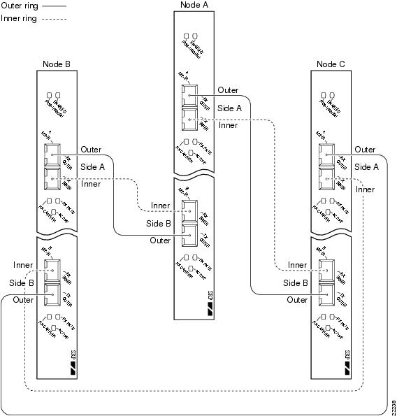
A DPT ring may contain as many as 32 nodes, or as few as 2 nodes. This section documents the layout and configuration of a three-node DPT ring. It is assumed that the actual physical installation of the Cisco 7200 series, Cisco 7200 VXR, Cisco uBR7246, or Cisco 7500 series router with VIP has already been accomplished.
Before the DPT ring can be created, each router (node) must have a DPT port adapter installed and configured. See the "Port Adapter Removal and Installation" section on page 3-7, and the "Configuring the DPT Interface" section. Once the individual nodes are configured, the inner and outer rings of the DPT ring must be connected as shown in Figure 4-1, and the DPT port adapters must be enabled. The following procedure describes the internodal connections of the DPT ring and the configuration commands used to create the ring.
Figure 4-1 Three-Node DPT Ring

Step 1 ![]() While in configuration mode, use the shutdown command to disable the DPT port adapter on each node, as shown below:
While in configuration mode, use the shutdown command to disable the DPT port adapter on each node, as shown below:
Router(config)# interface srp 1/0
Router(config-if)# shutdown
Step 2 ![]() Connect the nodes as shown in Figure 4-2, being careful to observe the receive (RX) and transmit (TX) cable relationship. Table 4-5 lists the internodal cable connections for a three-node DPT ring.
Connect the nodes as shown in Figure 4-2, being careful to observe the receive (RX) and transmit (TX) cable relationship. Table 4-5 lists the internodal cable connections for a three-node DPT ring.
Note ![]() Side A (RX outer/TX inner) of the DPT port adapter must be connected to side B (TX outer/RX inner) of the DPT port adapter in the next node in the ring. See Figure 4-2 for the correct orientation of side A and side B.
Side A (RX outer/TX inner) of the DPT port adapter must be connected to side B (TX outer/RX inner) of the DPT port adapter in the next node in the ring. See Figure 4-2 for the correct orientation of side A and side B.
Figure 4-2 Internodal Connections of a Three-Node DPT Ring
Step 3 ![]() Use the no shutdown command to enable the DPT port adapter of each node, as shown below:
Use the no shutdown command to enable the DPT port adapter of each node, as shown below:
Router(config)# interface srp 1/0
Router(config-if)# no shutdown
Step 4 ![]() Use the show srp topology command to verify that the all three nodes are recognized as part of the DPT ring. The output shows the number of nodes on the ring and their MAC addresses. See the "Using show Commands to Check System Status" section.
Use the show srp topology command to verify that the all three nodes are recognized as part of the DPT ring. The output shows the number of nodes on the ring and their MAC addresses. See the "Using show Commands to Check System Status" section.
Adding or Removing Nodes in a DPT Ring
The following sections describe the procedures for adding or removing a node in a DPT ring:
•![]() Removing a Node from a DPT Ring
Removing a Node from a DPT Ring
Adding a Node to a DPT Ring
When you want to install a new node in a DPT ring, you must first install and configure a DPT port adapter in the Cisco 7200 series, Cisco 7200 VXR, Cisco uBR7246, or Cisco 7500 series router with VIP, and then install and configure the router as a node in the DPT ring. This section describes the procedure for adding a node to a DPT ring.
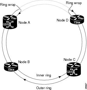
To add a node to a DPT ring, you must first reroute the traffic flow over the ring through an alternate path by creating a ring wrap where the new node is to be installed. Figure 4-3 shows a four-node DPT ring. Use the following procedure to add a node between nodes A and D on the ring:
Step 1 ![]() While in global configuration mode, stop data traffic between nodes A and D on the DPT ring by entering the forced-switch command srp ips request forced-switch a on the node A router. See the "Configuring the Intelligent Protection Switch Feature" section. This creates two ring wraps between the two nodes. (See Figure 4-4.)
While in global configuration mode, stop data traffic between nodes A and D on the DPT ring by entering the forced-switch command srp ips request forced-switch a on the node A router. See the "Configuring the Intelligent Protection Switch Feature" section. This creates two ring wraps between the two nodes. (See Figure 4-4.)
Figure 4-3 DPT Ring Topology with Four Nodes

Figure 4-4 DPT Ring with Ring Wraps Created by a Forced Switch
Step 2 ![]() From the configuration mode, enter the command show srp topology to verify that the ring wraps are in place. See the "Using show Commands to Check System Status" section.
From the configuration mode, enter the command show srp topology to verify that the ring wraps are in place. See the "Using show Commands to Check System Status" section.
Step 3 ![]() Disconnect the fiber-optic cables connecting side A of node A to side B of node D. (See Figure 4-4).
Disconnect the fiber-optic cables connecting side A of node A to side B of node D. (See Figure 4-4).
Step 4 ![]() Connect side A of node A to side B of the new node (node E), using two simplex or one duplex fiber-optic cable. See the "Cables, Connectors, and Pinouts" section on page 1-6. Connect side A of the new node to side B of node D. (See Figure 4-5).
Connect side A of node A to side B of the new node (node E), using two simplex or one duplex fiber-optic cable. See the "Cables, Connectors, and Pinouts" section on page 1-6. Connect side A of the new node to side B of node D. (See Figure 4-5).
Note ![]() Be careful to observe the proper cable orientation. When using duplex cables, you must reverse one of the cable ends for correct orientation.
Be careful to observe the proper cable orientation. When using duplex cables, you must reverse one of the cable ends for correct orientation.
Step 5 ![]() If the DPT port adapter in the new router (node E) has not been configured, do so at this time. See the "Configuring the DPT Interface" section.
If the DPT port adapter in the new router (node E) has not been configured, do so at this time. See the "Configuring the DPT Interface" section.
Step 6 ![]() Enter the no shutdown command to bring up the node E router.
Enter the no shutdown command to bring up the node E router.
Step 7 ![]() Confirm that the system recognizes the new node by entering the show srp topology command. The output shows the number of nodes on the ring, their MAC addresses, and the state of the nodes (wrapped or not).
Confirm that the system recognizes the new node by entering the show srp topology command. The output shows the number of nodes on the ring, their MAC addresses, and the state of the nodes (wrapped or not).
Step 8 ![]() Remove the two ring wraps created by the forced switch on nodes A and D by entering the no srp ips request forced-switch a command on the node A router.
Remove the two ring wraps created by the forced switch on nodes A and D by entering the no srp ips request forced-switch a command on the node A router.
Step 9 ![]() Confirm that the ring wraps are no longer in place by entering the show srp topology command. The output shows the number of nodes on the ring, their MAC addresses, and the state of the nodes (wrapped or not).
Confirm that the ring wraps are no longer in place by entering the show srp topology command. The output shows the number of nodes on the ring, their MAC addresses, and the state of the nodes (wrapped or not).
Figure 4-5 DPT Ring Topology with an Added Node

Note ![]() You can add a node to a DPT ring without entering the srp ips forced-switch command, but you then cannot control when the traffic is rerouted and restored; the system determines the time instead.
You can add a node to a DPT ring without entering the srp ips forced-switch command, but you then cannot control when the traffic is rerouted and restored; the system determines the time instead.
Removing a Node from a DPT Ring
This section describes the procedure for removing a node from a DPT ring. The following steps describe how to remove node D from a four-node DPT ring, similar to that shown in Figure 4-3.
Step 1 ![]() Isolate node D by entering the forced-switch command srp ips request forced-switch a on the node A router, and srp ips request forced-switch b on the node C router.
Isolate node D by entering the forced-switch command srp ips request forced-switch a on the node A router, and srp ips request forced-switch b on the node C router.
Step 2 ![]() Enter the show srp topology command on either router to verify that the ring wraps are in place and that node D no longer exists on the ring.
Enter the show srp topology command on either router to verify that the ring wraps are in place and that node D no longer exists on the ring.
Step 3 ![]() Disconnect both ends of the cable connecting side A of node D to side B of node C.
Disconnect both ends of the cable connecting side A of node D to side B of node C.
Step 4 ![]() Disconnect the cable connected to side B of node D and connect it to side B of node C.
Disconnect the cable connected to side B of node D and connect it to side B of node C.
Step 5 ![]() Remove the two ring wraps created by the forced switch on nodes A and C by entering the no srp ips request forced-switch a command on node A, and no srp ips request forced-switch b command on node C.
Remove the two ring wraps created by the forced switch on nodes A and C by entering the no srp ips request forced-switch a command on node A, and no srp ips request forced-switch b command on node C.
Step 6 ![]() Enable IP routing by entering the ip routing command to restart data traffic.
Enable IP routing by entering the ip routing command to restart data traffic.
This completes the procedure for removing a node from a DPT ring.
Checking the Configuration
After configuring the new interface, use the show commands to display the status of the new interface or all interfaces, and use the ping and loopback commands to check connectivity. This section includes the following subsections:
•![]() Using show Commands to Verify the New Interface Status
Using show Commands to Verify the New Interface Status
•![]() Using the ping Command to Verify Network Connectivity
Using the ping Command to Verify Network Connectivity
Using show Commands to Verify the New Interface Status
Table 4-6 demonstrates how you can use the show commands to verify that new interfaces are configured and operating correctly and that the DPT port adapter appears in them correctly. Sample displays of the output of selected show commands appear in the sections that follow. For complete command descriptions and examples, refer to the publications listed in the "Related Documentation" section.
Note ![]() The outputs that appear in this document may not match the output you receive when running these commands. The outputs in this document are examples only.
The outputs that appear in this document may not match the output you receive when running these commands. The outputs in this document are examples only.
|
|
|
|
|---|---|---|
show version or |
Displays system hardware configuration, the number of each interface type installed, Cisco IOS software version, names and sources of configuration files, and boot images |
Router# show version |
show controllers |
Displays all the current interface processors and their interfaces |
Router# show controllers |
show diag slot |
Displays types of port adapters installed in your system and information about a specific port adapter slot, interface processor slot, or chassis slot |
Router# show diag 2 |
show interfaces type port-adapter-slot-number/ |
Displays status information about a specific type of interface (for example, srp) in a Cisco 7200 series router |
Router# show interfaces srp 1/0 |
show interfaces type 1 /interface-port-number |
Displays status information about a specific type of interface (for example, srp) in a Cisco uBR7246 router |
Router# show interfaces srp 1/0 |
show protocols |
Displays protocols configured for the entire system and for specific interfaces |
Router# show protocols |
show running-config |
Displays the running configuration file |
Router# show running-config |
show startup-config |
Displays the configuration stored in NVRAM |
Router# show startup-config |
1 Refer to "Identifying Interface Addresses" section on page 1-10 for interface addresses on the Cisco 7500 series routers with VIP. |
If an interface is shut down and you configured it as up, or if the displays indicate that the hardware is not functioning properly, ensure that the interface is properly connected and terminated. If you still have problems bringing up the interface, contact a service representative for assistance. This section includes the following subsections:
•![]() Using the show version or show hardware Commands
Using the show version or show hardware Commands
•![]() Using the show interfaces Command
Using the show interfaces Command
Choose the subsection appropriate for your system. Proceed to the "Using the ping Command to Verify Network Connectivity" section when you have finished using the show commands.
Using the show version or show hardware Commands
Display the configuration of the system hardware, the number of each interface type installed, the Cisco IOS software version, the names and sources of configuration files, and the boot images, using the show version (or show hardware) command.
Note ![]() The outputs that appear in this document may not match the output you receive when running these commands. The outputs in this document are examples only.
The outputs that appear in this document may not match the output you receive when running these commands. The outputs in this document are examples only.
Cisco 7200 Series and Cisco uBR7200 Series Routers
Following is an example of the show version command from a Cisco 7200 series router with the DPT port adapter:
Router# show version
Cisco Internetwork Operating System Software
IOS (tm) 7200 Software (C7200-J-M), Version 11.1(7)CA [biff 105]
Copyright (c) 1986-1996 by cisco Systems, Inc.
Compiled Sun 04-Aug-96 06:00 by biff
Image text-base: 0x600088A0, data-base: 0x605A4000
ROM: System Bootstrap, Version 11.1(7)CA RELEASED SOFTWARE
Router uptime is 4 hours, 22 minutes
System restarted by reload
System image file is "c7200-j-mz", booted via slot0
cisco 7206 (NPE150) processor with 12288K/4096K bytes of memory.
R4700 processor, Implementation 33, Revision 1.0 (Level 2 Cache)
Last reset from power-on
Bridging software.
SuperLAT software (copyright 1990 by Meridian Technology Corp).
X.25 software, Version 2.0, NET2, BFE and GOSIP compliant.
TN3270 Emulation software (copyright 1994 by TGV INC).
Chassis Interface.
4 Ethernet/IEEE 802.3 interfaces.
2 FastEthernet/IEEE 802.3 interfaces.
4 Token Ring /IEEE802.5 interfaces.
12 Serial network interfaces.
1 Compression port adapter.
125K bytes of non-volatile configuration memory.
1024K bytes of packet SRAM memory.
20480K bytes of Flash PCMCIA card at slot 0 (Sector size 128K).
8192K bytes of Flash internal SIMM (Sector size 256K).
Configuration register is 0x2
Using the show diag Command
Display the types of port adapters installed in your system (and specific information about each) using the show diag slot command, where slot is the port adapter slot in a Cisco 7200 series, Cisco uBR7200, and Cisco 7500 series routers with VIP.
Note ![]() The outputs that appear in this document may not match the output you receive when running these commands. The outputs in this document are examples only.
The outputs that appear in this document may not match the output you receive when running these commands. The outputs in this document are examples only.
Cisco 7200 Series and Cisco uBR7200 Series Routers
Following is an example of the show diag slot command that shows a DPT port adapter in port adapter slot 1 of a Cisco 7200 series router:
Router# show diag 1
Slot 1:
Mueslix serial (RS232) port adapter, 8 ports
Port adapter is analyzed
Port adapter insertion time 2d09h ago
Hardware revision 255.255 Board revision UNKNOWN
Serial number 4294967295 Part number 255-65535-255
Test history 0xFF RMA number 255-255-255
EEPROM format version 1
EEPROM contents (hex):
0x20: 01 0D FF FF FF FF FF FF FF FF FF FF FF FF FF FF
0x30: FF FF FF FF FF FF FF FF FF FF FF FF FF FF FF FF
Note ![]() Port adapters used with Cisco 7200 VXR routers require the correct base hardware revision in order to function. The following error message occurs on bootup if the incorrect hardware revision is used:
Port adapters used with Cisco 7200 VXR routers require the correct base hardware revision in order to function. The following error message occurs on bootup if the incorrect hardware revision is used:
> PA-3-REVNOTSUPPORTED:PA in slot 1 (Ethernet) requires base h/w revision of (1.14) for this chassisUse the show diag command to display the hardware revision.
Using the show interfaces Command
The show interfaces command displays status information (including the physical slot and interface address) for the interfaces you specify. All of the examples that follow specify srp interfaces.
For complete descriptions of interface subcommands and the configuration options available for Cisco 7200, Cisco uBR7200, and Cisco 7500 series routers, refer to the publications listed in the "Related Documentation" section.
Note ![]() The outputs that appear in this document may not match the output you receive when running these commands. The outputs in this document are examples only.
The outputs that appear in this document may not match the output you receive when running these commands. The outputs in this document are examples only.
Cisco 7200 Series and Cisco uBR7200 Series Routers
Following is an example of the show interfaces command for Cisco 7200 series and Cisco uBR7200 series routers. Following is an example of the show interfaces srp command, which shows all of the information specific to interface port 0 on a DPT port adapter installed in port adapter slot 1:
Router# show interfaces srp 1/0
SRP1/0 is up, line protocol is up
Hardware is SRP, address is 0010.0ba6.408c (bia 0010.0ba6.408c)
Internet address is 10.2.2.3/24
MTU 4470 bytes, BW 622000 Kbit, DLY 100 usec, rely 255/255, load 1/255
Encapsulation SRP, loopback not set
Last input 00:00:00, output 00:00:00, output hang never
Last clearing of "show interface" counters 1w3d
Queueing strategy: fifo
Output queue 0/40, 0 drops; input queue 0/75, 0 drops
5 minute input rate 0 bits/sec, 2 packets/sec
5 minute output rate 0 bits/sec, 0 packets/sec
2369845 packets input, 158630960 bytes, 0 no buffer
Received 0 broadcasts, 0 runts, 0 giants, 0 throttles
0 input errors, 0 CRC, 0 frame, 0 overrun, 0 ignored, 0 abort
2369516 packets output, 158542697 bytes, 0 underruns
0 output errors, 0 collisions, 1 interface resets
0 output buffer failures, 0 output buffers swapped out
Side A received errors:
0 input errors, 0 CRC, 0 runts, 0 giants, 0 ignored, 0 abort
Side B received errors:
0 input errors, 0 CRC, 0 runts, 0 giants, 0 ignored, 0 abort
Using the ping Command to Verify Network Connectivity
Using the ping command, you can verify that an interface port is functioning properly. This section provides a brief description of this command. Refer to the publications listed in the "Related Documentation" section for detailed command descriptions and examples.
The ping command sends echo request packets out to a remote device at an IP address that you specify. After sending an echo request, the system waits a specified time for the remote device to reply. Each echo reply is displayed as an exclamation point (!) on the console terminal; each request that is not returned before the specified timeout is displayed as a period (.). A series of exclamation points (!!!!!) indicates a good connection; a series of periods (.....) or the messages [timed out] or [failed] indicate a bad connection.
Following is an example of a successful ping command to a remote server with the address 10.0.0.10:
Router# ping 10.0.0.10 <Return>
Type escape sequence to abort.
Sending 5, 100-byte ICMP Echoes to 10.0.0.10, timeout is 2 seconds:
!!!!!
Success rate is 100 percent (5/5), round-trip min/avg/max = 1/15/64 ms
Router#
If the connection fails, verify that you have the correct IP address for the destination and that the device is active (powered on), and repeat the ping command.
 Feedback