PA-FE 100BaseT Fast Ethernet Port Adapter Installation and Configuration
Bias-Free Language
The documentation set for this product strives to use bias-free language. For the purposes of this documentation set, bias-free is defined as language that does not imply discrimination based on age, disability, gender, racial identity, ethnic identity, sexual orientation, socioeconomic status, and intersectionality. Exceptions may be present in the documentation due to language that is hardcoded in the user interfaces of the product software, language used based on RFP documentation, or language that is used by a referenced third-party product. Learn more about how Cisco is using Inclusive Language.
- Updated:
- September 14, 2007
Chapter: Removing and Installing the PA-FE
- Handling Port Adapters
- Online Insertion and Removal
- Warnings and Cautions
- Port Adapter Removal and Installation
- Catalyst 5000 Family Switches with RSM/VIP2—Removing and Installing a Port Adapter
- Cisco 7100 Series Routers—Removing and Installing a Port Adapter
- Cisco 7200 Series Routers and Cisco 7200 VXR Routers—Removing and Installing a Port Adapter
- Cisco uBR7200 Series Routers—Removing a Port Adapter
- Cisco uBR7200 Series Routers—Installing a Port Adapter
- Cisco 7301 Router—Removing and Installing a Port Adapter
- Cisco 7304 PCI Port Adapter Carrier Card—Removing and Installing a Port Adapter
- Cisco 7401ASR Router—Removing and Installing a Port Adapter
- Cisco 7000 Series Routers and Cisco 7500 Series Routers with VIP—Removing and Installing a Single-Width Port Adapter
- Connecting PA-FE-TX and PA-FE-FX Port Adapter Interface Cables
Removing and Installing Port Adapters
This chapter describes how to remove the PA-FE-TX and PA-FE-FX port adapters from supported platforms and also how to install a new or replacement port adapter. This chapter contains the following sections:
•![]() Port Adapter Removal and Installation
Port Adapter Removal and Installation
•![]() Connecting PA-FE-TX and PA-FE-FX Port Adapter Interface Cables
Connecting PA-FE-TX and PA-FE-FX Port Adapter Interface Cables
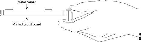
Each port adapter circuit board is mounted to a metal carrier and is sensitive to electrostatic discharge (ESD) damage. Before you begin installation, read Chapter 2, "Preparing for Installation," for a list of parts and tools required for installation.

Note ![]() When a slot is not in use, a blank must fill the empty slot to allow the router or switch to conform to electromagnetic interference (EMI) emissions requirements and to allow proper airflow across the installed port adapters. If you plan to install a new port adapter in a slot that is not in use, you must first remove the blank.
When a slot is not in use, a blank must fill the empty slot to allow the router or switch to conform to electromagnetic interference (EMI) emissions requirements and to allow proper airflow across the installed port adapters. If you plan to install a new port adapter in a slot that is not in use, you must first remove the blank.

Handling Port Adapters
Figure 3-1 Handling a Port Adapter
Online Insertion and Removal
The Cisco 7100 series routers, Cisco 7200 series routers, Cisco 7200 VXR routers, Cisco uBR7246 router, Cisco 7301 routers, and the Cisco 7401ASR routers support the OIR of all module types. Therefore, you do not have to power down routers when removing and replacing modules in these chassis.
Regarding the Catalyst 5000 family switches, Cisco 7000 series routers, and Cisco 7500 series routers, the VIP does not support OIR of individual port adapters. To remove or install port adapters on a Catalyst RSM/VIP2, VIP, or Cisco 7304 PCI Port Adapter Carrier Card you must first remove the Catalyst RSM/VIP2, VIP, or the Cisco 7304 PCI Port Adapter Carrier Card from the router and then remove or install the port adapter as required.
Note ![]() As you disengage the module from the router or switch, online insertion and removal (OIR) administratively shuts down all active interfaces in the module.
As you disengage the module from the router or switch, online insertion and removal (OIR) administratively shuts down all active interfaces in the module.
Warnings and Cautions
Observe the following warnings and cautions when installing or removing modules:
•![]() Do not slide a module all the way into the slot until you have connected all required cables. Trying to do so disrupts normal operation of the router or switch.
Do not slide a module all the way into the slot until you have connected all required cables. Trying to do so disrupts normal operation of the router or switch.
•![]() If a module lever or other retaining mechanism does not move to the locked position, the module is not completely seated in the midplane. Carefully pull the module halfway out of the slot, reinsert it, and move the module lever or other mechanism to the locked position.
If a module lever or other retaining mechanism does not move to the locked position, the module is not completely seated in the midplane. Carefully pull the module halfway out of the slot, reinsert it, and move the module lever or other mechanism to the locked position.
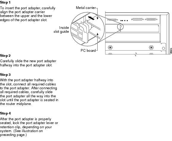
•![]() To prevent jamming the carrier between the upper and the lower edges of the module slot, and to ensure that the edge connector at the rear of the module mates with the connection at the rear of the module slot, make certain that the carrier is positioned correctly, as shown in the cutaway in the following illustrations.
To prevent jamming the carrier between the upper and the lower edges of the module slot, and to ensure that the edge connector at the rear of the module mates with the connection at the rear of the module slot, make certain that the carrier is positioned correctly, as shown in the cutaway in the following illustrations.

Warning ![]() Hazardous voltage or energy is present on the backplane when the system is operating. Use caution when servicing. Statement 1034
Hazardous voltage or energy is present on the backplane when the system is operating. Use caution when servicing. Statement 1034
Port Adapter Removal and Installation
In this section there are step-by-step instructions on how to remove and install port adapters. Although the procedures may refer to a particular type of port adapter, the steps are the same for installing and removing all types of port adapters.
•![]() Catalyst 5000 Family Switches with RSM/VIP2—Removing and Installing a Port Adapter
Catalyst 5000 Family Switches with RSM/VIP2—Removing and Installing a Port Adapter
•![]() Cisco 7100 Series Routers—Removing and Installing a Port Adapter
Cisco 7100 Series Routers—Removing and Installing a Port Adapter
•![]() Cisco 7200 Series Routers and Cisco 7200 VXR Routers—Removing and Installing a Port Adapter
Cisco 7200 Series Routers and Cisco 7200 VXR Routers—Removing and Installing a Port Adapter
•![]() Cisco uBR7200 Series Routers—Removing a Port Adapter
Cisco uBR7200 Series Routers—Removing a Port Adapter
•![]() Cisco uBR7200 Series Routers—Installing a Port Adapter
Cisco uBR7200 Series Routers—Installing a Port Adapter
•![]() Cisco 7301 Router—Removing and Installing a Port Adapter
Cisco 7301 Router—Removing and Installing a Port Adapter
•![]() Cisco 7304 PCI Port Adapter Carrier Card—Removing and Installing a Port Adapter
Cisco 7304 PCI Port Adapter Carrier Card—Removing and Installing a Port Adapter
•![]() Cisco 7401ASR Router—Removing and Installing a Port Adapter
Cisco 7401ASR Router—Removing and Installing a Port Adapter
Catalyst 5000 Family Switches with RSM/VIP2—Removing and Installing a Port Adapter

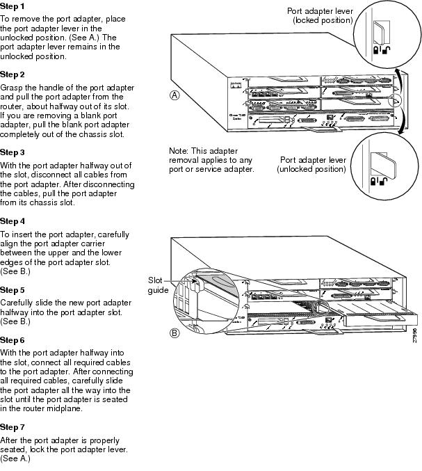
Cisco 7100 Series Routers—Removing and Installing a Port Adapter
Cisco 7200 Series Routers and Cisco 7200 VXR Routers—Removing and Installing a Port Adapter
Cisco uBR7200 Series Routers—Removing a Port Adapter
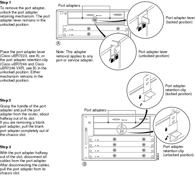
Cisco uBR7200 Series Routers—Installing a Port Adapter
Cisco 7301 Router—Removing and Installing a Port Adapter

Cisco 7304 PCI Port Adapter Carrier Card—Removing and Installing a Port Adapter
You can install one single-width port adapter in a Cisco 7304 PCI Port Adapter Carrier Card. This section provides step-by-step instructions for removing and installing a port adapter in a Cisco 7304 PCI Port Adapter Carrier Card.
Warning ![]() Hazardous voltage or energy is present on the backplane when the system is operating. Use caution when servicing. Statement 1034
Hazardous voltage or energy is present on the backplane when the system is operating. Use caution when servicing. Statement 1034
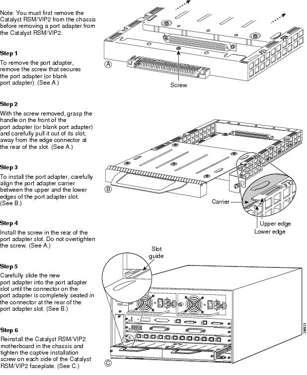
To remove and install a port adapter in a Cisco 7304 PCI Port Adapter Carrier Card, refer to Figure 3-2 and do the following:
Step 1 ![]() If the Cisco 7304 PCI Port Adapter Carrier Card is still in the router, you must remove the Cisco 7304 PCI Port Adapter Carrier Card before removing a port adapter.
If the Cisco 7304 PCI Port Adapter Carrier Card is still in the router, you must remove the Cisco 7304 PCI Port Adapter Carrier Card before removing a port adapter.
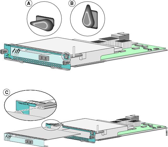
Step 2 ![]() To remove the port adapter from the Cisco 7304 PCI Port Adapter Carrier Card, turn the port adapter lock from its locked and horizontal position shown in A of Figure 3-2 to its unlocked and vertical position shown in B of Figure 3-2.
To remove the port adapter from the Cisco 7304 PCI Port Adapter Carrier Card, turn the port adapter lock from its locked and horizontal position shown in A of Figure 3-2 to its unlocked and vertical position shown in B of Figure 3-2.
Step 3 ![]() Grasp the handle of the port adapter and pull the port adapter from the Cisco 7304 PCI Port Adapter Carrier Card. (You have already disconnected the cables from the port adapter when removing the Cisco 7304 PCI Port Adapter Carrier Card).
Grasp the handle of the port adapter and pull the port adapter from the Cisco 7304 PCI Port Adapter Carrier Card. (You have already disconnected the cables from the port adapter when removing the Cisco 7304 PCI Port Adapter Carrier Card).
Step 4 ![]() To insert the port adapter in the Cisco 7304 PCI Port Adapter Carrier Card, locate the guide rails inside the Cisco 7304 PCI Port Adapter Carrier Card that hold the port adapter in place. They are at the top left and top right of the port adapter slot and are recessed about an inch, as shown in C of Figure 3-2.
To insert the port adapter in the Cisco 7304 PCI Port Adapter Carrier Card, locate the guide rails inside the Cisco 7304 PCI Port Adapter Carrier Card that hold the port adapter in place. They are at the top left and top right of the port adapter slot and are recessed about an inch, as shown in C of Figure 3-2.
Step 5 ![]() Carefully slide the port adapter in theCisco 7304 PCI Port Adapter Carrier Card until the port adapter makes contact with the port adapter interface connector. When fully seated, the port adapter front panel should be flush with the face of the Cisco 7304 PCI Port Adapter Carrier Card.
Carefully slide the port adapter in theCisco 7304 PCI Port Adapter Carrier Card until the port adapter makes contact with the port adapter interface connector. When fully seated, the port adapter front panel should be flush with the face of the Cisco 7304 PCI Port Adapter Carrier Card.
Step 6 ![]() After the port adapter is properly seated, turn the port adapter lock to its locked and horizontal position, as shown in A of Figure 3-2.
After the port adapter is properly seated, turn the port adapter lock to its locked and horizontal position, as shown in A of Figure 3-2.
Figure 3-2 illustrates how to remove and install a port adapter in a Cisco 7304 PCI Port Adapter Carrier Card.
Figure 3-2 Cisco 7304 PCI Port Adapter Carrier Card—Port Adapter Removal and Installation
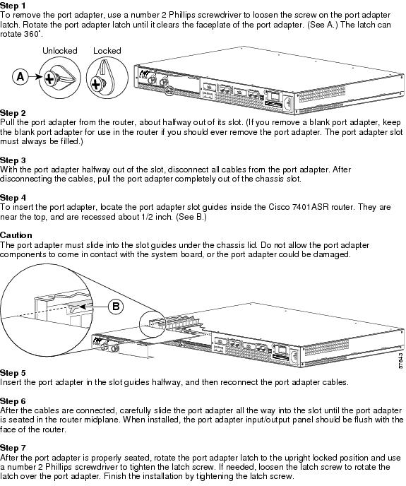
Cisco 7401ASR Router—Removing and Installing a Port Adapter
Cisco 7000 Series Routers and Cisco 7500 Series Routers with VIP—Removing and Installing a Single-Width Port Adapter

Connecting PA-FE-TX and PA-FE-FX Port Adapter Interface Cables
To continue your PA-FE-TX and PA-FE-FX port adapter installation, you must install the interface cables. The following instructions apply to all supported platforms.
PA-FE-TX and PA-FE-FX Port Adapter RJ-45 and MII Connections
On a single PA-FE, you can use either the RJ-45 (or SC for PA-FE-FX) connection or the MII connection. (RJ-45, SC, and MII cables are not available from Cisco Systems; they are available from outside commercial cable vendors.) If you have two PA-FE port adapters on your VIP or Catalyst RSM/VIP2, you can use the RJ-45 (or SC for PA-FE-FX) connection on one port adapter and the MII connection on the other port adapter.
Attaching PA-FE-TX and PA-FE-FX Port Adapter Interface Cables
Use the following procedure to connect RJ-45 (or SC for PA-FE-FX) and MII cables:
Step 1 ![]() If you have MII connections, attach an MII cable directly to the MII receptacle on the PA-FE-TX and PA-FE-FX or attach a 100BASE--T transceiver, with the media appropriate to your application, to the MII receptacle on the PA-FE-TX and PA-FE-FX. (See Figure 3-3 for the PA-FE-TX and Figure 3-4 for the PA-FE-FX.)
If you have MII connections, attach an MII cable directly to the MII receptacle on the PA-FE-TX and PA-FE-FX or attach a 100BASE--T transceiver, with the media appropriate to your application, to the MII receptacle on the PA-FE-TX and PA-FE-FX. (See Figure 3-3 for the PA-FE-TX and Figure 3-4 for the PA-FE-FX.)
If you have RJ-45 connections, attach the Category 5 UTP cable directly to the RJ-45 port on the PA-FE-TX and PA-FE-FX. (See Figure 3-3 for PA-FE-TX and Figure 3-4 for PA-FE-FX.) The PA-FE-TX and PA-FE-FX is an end station device and not a repeater. You must connect the PA-FE-TX and PA-FE-FX to a repeater or hub.
If you have an SC connection (PA-FE-FX), attach the cable directly to the SC port on the PA-FE-FX. (See Figure 3-4.) Use either one duplex SC connector or two simplex SC connectors, and observe the correct relationship between the receive (RX) and transmit (TX) ports on the PA-FE-FX and your repeater.
Note ![]() Each PA-FE-FX or PA-FE-TX can have either an MII attachment or an RJ-45 (or SC) attachment, but not both simultaneously. The MII and RJ-45 (or SC) receptacles represent two physical connection options for one Fast Ethernet interface.
Each PA-FE-FX or PA-FE-TX can have either an MII attachment or an RJ-45 (or SC) attachment, but not both simultaneously. The MII and RJ-45 (or SC) receptacles represent two physical connection options for one Fast Ethernet interface.
Figure 3-3 Connecting PA-FE-TX MII or RJ-45 Cables—Horizontal Orientation Shown Without Handles

Figure 3-4 Connecting PA-FE-FX MII or SC Cables—Horizontal Orientation Shown Without Handles

Warning ![]() Invisible laser radiation may be emitted from disconnected fibers or connectors. Do not stare into beams or view directly with optical instruments. Statement 1051
Invisible laser radiation may be emitted from disconnected fibers or connectors. Do not stare into beams or view directly with optical instruments. Statement 1051
Step 2 ![]() For the PA-FE-TX, attach the ferrite bead to the RJ-45 cable (at either end), as shown in Figure 3-5.
For the PA-FE-TX, attach the ferrite bead to the RJ-45 cable (at either end), as shown in Figure 3-5.
Figure 3-5 Attaching the Ferrite Bead around the RJ-45 Cable

Step 3 ![]() Attach the network end of your RJ-45 (or SC) or MII cable to your 100BASE-T transceiver, switch, hub, repeater, DTE, or other external 100BASE-T equipment.
Attach the network end of your RJ-45 (or SC) or MII cable to your 100BASE-T transceiver, switch, hub, repeater, DTE, or other external 100BASE-T equipment.
Note ![]() After your MII transceiver is connected and the PA-FE-TX and PA-FE-FX interface is configured as up, you can verify that your MII transceiver responds to physical sublayer (PHY) address 0 by disconnecting the transceiver from the MII receptacle; if the PA-FE-TX and PA-FE-FX interface goes down, then your MII transceiver responds to PHY address 0.
After your MII transceiver is connected and the PA-FE-TX and PA-FE-FX interface is configured as up, you can verify that your MII transceiver responds to physical sublayer (PHY) address 0 by disconnecting the transceiver from the MII receptacle; if the PA-FE-TX and PA-FE-FX interface goes down, then your MII transceiver responds to PHY address 0.
This completes the PA-FE-TX and PA-FE-FX port adapter cable installation.
 Feedback