Installing and Removing the SSL Services Module
This chapter describes how to install the SSL Services Module into the Catalyst 6500 series switch and contains these sections:
•![]() Installing the SSL Services Module
Installing the SSL Services Module
•![]() Removing the SSL Services Module
Removing the SSL Services Module
System Requirements
Before you install the SSL Services Module into the Catalyst 6500 series switch, make sure that the switch meets the hardware and software requirements listed in Table 2-1.
Safety Overview
Safety warnings appear throughout this publication in procedures that, if performed incorrectly, may harm you. A warning symbol precedes each warning statement.

Warning ![]() This warning symbol means danger. You are in a situation that could cause bodily injury. Before you work on any equipment, be aware of the hazards involved with electrical circuitry and be familiar with standard practices for preventing accidents. To see translations of the warnings that appear in this publication, refer to the Regulatory Compliance and Safety Information document that accompanied this device.
This warning symbol means danger. You are in a situation that could cause bodily injury. Before you work on any equipment, be aware of the hazards involved with electrical circuitry and be familiar with standard practices for preventing accidents. To see translations of the warnings that appear in this publication, refer to the Regulatory Compliance and Safety Information document that accompanied this device.
Warning ![]() Before you install, operate, or service the system, read the Site Preparation and Safety Guide. This guide contains important safety information you should know before working with the system.
Before you install, operate, or service the system, read the Site Preparation and Safety Guide. This guide contains important safety information you should know before working with the system.
Warning ![]() Only trained and qualified personnel should be allowed to install, replace, or service this equipment.
Only trained and qualified personnel should be allowed to install, replace, or service this equipment.
Warning ![]() During this procedure, wear grounding wrist straps to avoid ESD damage to the card. Do not directly touch the backplane with your hand or any metal tool, or you could shock yourself.
During this procedure, wear grounding wrist straps to avoid ESD damage to the card. Do not directly touch the backplane with your hand or any metal tool, or you could shock yourself.
Warning ![]() Blank faceplates and cover panels serve three important functions: they prevent exposure to hazardous voltages and currents inside the chassis; they contain electromagnetic interference (EMI) that might disrupt other equipment; and they direct the flow of cooling air through the chassis. Do not operate the system unless all cards, faceplates, front covers, and rear covers are in place.
Blank faceplates and cover panels serve three important functions: they prevent exposure to hazardous voltages and currents inside the chassis; they contain electromagnetic interference (EMI) that might disrupt other equipment; and they direct the flow of cooling air through the chassis. Do not operate the system unless all cards, faceplates, front covers, and rear covers are in place.
Installing the SSL Services Module
The following sections describe how to install the SSL Services Module into the Catalyst 6500 series switch:
•![]() Preparing to Install the SSL Services Module
Preparing to Install the SSL Services Module
•![]() Installing the SSL Services Module
Installing the SSL Services Module
Preparing to Install the SSL Services Module
Before installing the SSL Services Module, make sure that the following items are available:
•![]() Catalyst 6500 series switch chassis
Catalyst 6500 series switch chassis
•![]() Management station that is available through a Telnet or a console connection to perform configuration tasks
Management station that is available through a Telnet or a console connection to perform configuration tasks
Required Tools
Warning ![]() Only trained and qualified personnel should be allowed to install, replace, or service this equipment.
Only trained and qualified personnel should be allowed to install, replace, or service this equipment.
These tools are required to install the SSL Services Module into the Catalyst 6500 series switch:
•![]() Flat-blade screwdriver
Flat-blade screwdriver
•![]() Wrist strap or other grounding device
Wrist strap or other grounding device
•![]() Antistatic mat or antistatic foam
Antistatic mat or antistatic foam
Installing the SSL Services Module

Note ![]() Before installing the SSL Services Module, you must install the Catalyst 6500 series switch chassis and at least one supervisor engine. For information on installing the switch chassis, refer to the Catalyst 6500 Series Installation Guide.
Before installing the SSL Services Module, you must install the Catalyst 6500 series switch chassis and at least one supervisor engine. For information on installing the switch chassis, refer to the Catalyst 6500 Series Installation Guide.
This section describes how to install the SSL Services Module into the Catalyst 6500 series switch.
Note ![]() All modules, including the supervisor engine (if you have redundant supervisor engines), support hot swapping. You can add, replace, or remove modules without interrupting the system power or causing other software or interfaces to shut down. For more information about hot-swapping modules, refer to the Catalyst 6500 Series Module Installation Guide.
All modules, including the supervisor engine (if you have redundant supervisor engines), support hot swapping. You can add, replace, or remove modules without interrupting the system power or causing other software or interfaces to shut down. For more information about hot-swapping modules, refer to the Catalyst 6500 Series Module Installation Guide.
Warning ![]() During this procedure, wear grounding wrist straps to avoid ESD damage to the card. Do not directly touch the backplane with your hand or any metal tool, or you could shock yourself.
During this procedure, wear grounding wrist straps to avoid ESD damage to the card. Do not directly touch the backplane with your hand or any metal tool, or you could shock yourself.
To install the SSL Services Module into the Catalyst 6500 series switch, perform these steps:
Step 1 ![]() Make sure that you take the necessary precautions to prevent ESD damage.
Make sure that you take the necessary precautions to prevent ESD damage.
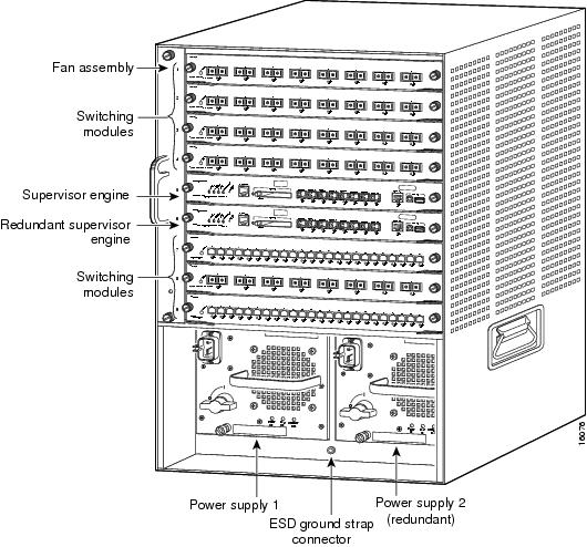
Step 2 ![]() Choose a slot for the SSL Services Module. See Figure 2-1 for the slot numbers on a Catalyst 6500 series switch.
Choose a slot for the SSL Services Module. See Figure 2-1 for the slot numbers on a Catalyst 6500 series switch.
Note ![]() Slot 1 is reserved for the supervisor engine. Slot 2 can contain an additional supervisor engine in case the supervisor engine in slot 1 fails. If a redundant supervisor engine is not required, you can insert the module in slots 2 through 6 on a 6-slot chassis, slots 2 through 9 on the 9-slot chassis, or slots 2 through 13 on the 13-slot chassis.
Slot 1 is reserved for the supervisor engine. Slot 2 can contain an additional supervisor engine in case the supervisor engine in slot 1 fails. If a redundant supervisor engine is not required, you can insert the module in slots 2 through 6 on a 6-slot chassis, slots 2 through 9 on the 9-slot chassis, or slots 2 through 13 on the 13-slot chassis.
Figure 2-1 Slot Numbers on Catalyst 6500 Series Switches
Step 3 ![]() Check that there is enough clearance to accommodate any interface equipment that you will be connecting directly to the supervisor engine or switching module ports.
Check that there is enough clearance to accommodate any interface equipment that you will be connecting directly to the supervisor engine or switching module ports.
Note ![]() If possible, place switching modules between the empty slots that contain only switching-module filler plates (Cisco part number 800-00292-01).
If possible, place switching modules between the empty slots that contain only switching-module filler plates (Cisco part number 800-00292-01).
Warning ![]() Blank faceplates (filler panels) serve three important functions: they prevent exposure to hazardous voltages and currents inside the chassis; they contain electromagnetic interference (EMI) that might disrupt other equipment; and they direct the flow of cooling air through the chassis. Do not operate the system unless all cards and faceplates are in place.
Blank faceplates (filler panels) serve three important functions: they prevent exposure to hazardous voltages and currents inside the chassis; they contain electromagnetic interference (EMI) that might disrupt other equipment; and they direct the flow of cooling air through the chassis. Do not operate the system unless all cards and faceplates are in place.
Step 4 ![]() Loosen the captive installation screws that secure the switching module filler plate (or an existing switching module) to the desired slot.
Loosen the captive installation screws that secure the switching module filler plate (or an existing switching module) to the desired slot.
Step 5 ![]() Remove the switching module filler plate (or an existing switching module).
Remove the switching module filler plate (or an existing switching module).
Step 6 ![]() Hold the handle of the SSL Services Module with one hand, and place your other hand under the carrier support. Do not touch the printed circuit boards or connector pins.
Hold the handle of the SSL Services Module with one hand, and place your other hand under the carrier support. Do not touch the printed circuit boards or connector pins.
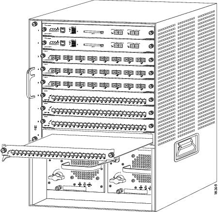
Step 7 ![]() Place the SSL Services Module in the slot. Align the notch on the sides of the switching module carrier with the groove in the slot. (See Figure 2-2.)
Place the SSL Services Module in the slot. Align the notch on the sides of the switching module carrier with the groove in the slot. (See Figure 2-2.)
Figure 2-2 Installing Modules in the Catalyst 6500 Series Switch
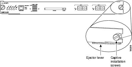
Step 8 ![]() Keep the SSL Services Module at a 90-degree angle to the backplane and carefully slide the SSL Services Module into the slot until the switching module faceplate contacts the ejector levers. (See Figure 2-3.)
Keep the SSL Services Module at a 90-degree angle to the backplane and carefully slide the SSL Services Module into the slot until the switching module faceplate contacts the ejector levers. (See Figure 2-3.)
Figure 2-3 Ejector Levers and Captive Installation Screws
Step 9 ![]() Using the thumb and forefinger of each hand, simultaneously push in the left and right levers to fully seat the SSL Services Module in the backplane connector.
Using the thumb and forefinger of each hand, simultaneously push in the left and right levers to fully seat the SSL Services Module in the backplane connector.

Note ![]() If you perform a hot swap, the console displays the message "Module n has been inserted." This message does not appear if you are connected to the Catalyst 6500 series switch through a Telnet session.
If you perform a hot swap, the console displays the message "Module n has been inserted." This message does not appear if you are connected to the Catalyst 6500 series switch through a Telnet session.
Step 10 ![]() Use a screwdriver to tighten the captive installation screws on the left and right ends of the SSL Services Module.
Use a screwdriver to tighten the captive installation screws on the left and right ends of the SSL Services Module.
This completes the SSL Services Module installation procedure.
Verifying the Installation
When you install the SSL Services Module into the Catalyst 6500 series switch, the module goes through a boot sequence that requires no intervention. At the successful conclusion of the boot sequence, the green STATUS LED will light and remain on. If the STATUS LED is not green, or is a different color, see Table 1-2 to determine the module's status.
Removing the SSL Services Module
This section describes how to remove the SSL Services Module from the Catalyst 6500 series switch.
Warning ![]() During this procedure, wear grounding wrist straps to avoid ESD damage to the card. Do not directly touch the backplane with your hand or any metal tool, or you could shock yourself.
During this procedure, wear grounding wrist straps to avoid ESD damage to the card. Do not directly touch the backplane with your hand or any metal tool, or you could shock yourself.
To remove the SSL Services Module, perform these steps:
Step 1 ![]() Shut down the module by one of these methods:
Shut down the module by one of these methods:
•![]() In privileged mode from the router prompt, enter the hw-mod module mod shutdown command.
In privileged mode from the router prompt, enter the hw-mod module mod shutdown command.
Note ![]() If you enter this command to shut down the module, you will have to enter the following commands in config mode to restart (power down, adn then power up) the module:
If you enter this command to shut down the module, you will have to enter the following commands in config mode to restart (power down, adn then power up) the module:
Router# no power enable module mod
Router# power enable module mod
•![]() If the module does not respond to any commands, use a small pointed object to access the SHUTDOWN button, which is located on the front panel of the module.
If the module does not respond to any commands, use a small pointed object to access the SHUTDOWN button, which is located on the front panel of the module.
Note ![]() Shutdown may require several minutes.
Shutdown may require several minutes.
Step 2 ![]() Verify that the SSL Services Module shuts down. Do not remove the module from the switch until the STATUS LED is off or orange.
Verify that the SSL Services Module shuts down. Do not remove the module from the switch until the STATUS LED is off or orange.
Step 3 ![]() Use a screwdriver to loosen the captive installation screws at the left and right sides of the module.
Use a screwdriver to loosen the captive installation screws at the left and right sides of the module.
Step 4 ![]() Grasp the left and right ejector levers. Simultaneously, pull the left lever to the left and the right lever to the right to release the module from the backplane connector.
Grasp the left and right ejector levers. Simultaneously, pull the left lever to the left and the right lever to the right to release the module from the backplane connector.
Step 5 ![]() As you pull the module out of the slot, place one hand under the carrier to support it. Avoid touching the module itself.
As you pull the module out of the slot, place one hand under the carrier to support it. Avoid touching the module itself.
Step 6 ![]() Carefully pull the module straight out of the slot, keeping one hand under the carrier to guide it. Keep the module at a 90-degree orientation to the backplane (horizontal to the floor).
Carefully pull the module straight out of the slot, keeping one hand under the carrier to guide it. Keep the module at a 90-degree orientation to the backplane (horizontal to the floor).
Step 7 ![]() Place the removed module on an antistatic mat or antistatic foam.
Place the removed module on an antistatic mat or antistatic foam.
Warning ![]() Blank faceplates and cover panels serve three important functions: they prevent exposure to hazardous voltages and currents inside the chassis; they contain electromagnetic interference (EMI) that might disrupt other equipment; and they direct the flow of cooling air through the chassis. Do not operate the system unless all cards, faceplates, front covers, and rear covers are in place.
Blank faceplates and cover panels serve three important functions: they prevent exposure to hazardous voltages and currents inside the chassis; they contain electromagnetic interference (EMI) that might disrupt other equipment; and they direct the flow of cooling air through the chassis. Do not operate the system unless all cards, faceplates, front covers, and rear covers are in place.
Step 8 ![]() If the slot is to remain empty, install a module filler plate to keep dust out of the chassis and to maintain proper airflow through the module compartment.
If the slot is to remain empty, install a module filler plate to keep dust out of the chassis and to maintain proper airflow through the module compartment.
 Feedback