- L2VPN Protocol-Based CLIs
- Any Transport over MPLS
- L2VPN Interworking
- L2VPN Pseudowire Preferential Forwarding
- L2VPN Multisegment Pseudowires
- MPLS Quality of Service
- QoS Policy Support for L2VPN ATM PVPs
- MPLS Pseudowire Status Signaling
- L2VPN VPLS Inter-AS Option B
- AToM Static Pseudowire Provisioning
- MPLS MTU Command Changes
- L2VPN Pseudowire Redundancy
- L2VPN Pseudowire Switching
- VPLS MAC Address Withdrawal
- Hot Standby Pseudowire Support for ATM and TDM Access Circuits
- Configuring Virtual Private LAN Services
- Routed Pseudo-Wire and Routed VPLS
- VPLS Autodiscovery BGP Based
- QoS Policies for VFI Pseudowires
- VPLS BGP Signaling L2VPN Inter-AS Option B
- Loop-Free Alternate Fast Reroute with L2VPN
- Finding Feature Information
- Prerequisites for L2VPN VPLS Inter-AS Option B
- Restrictions for L2VPN VPLS Inter-AS Option B
- Information About L2VPN VPLS Inter-AS Option B
- Modifying the VPLS Autodiscovery Settings for Use with L2VPN VPLS Inter-AS Option B
- Modifying the VPLS Autodiscovery Settings for Use with L2VPN VPLS Inter-AS Option B using the commands associated with the L2VPN Protocol-Based CLIs feature
- Enabling L2VPN VPLS Inter-AS Option B on the ASBR
- Enabling L2VPN VPLS Inter-AS Option B on the ASBR using the commands associated with the L2VPN Protocol-Based CLIs feature
- Enabling L2VPN VPLS Inter-AS Option B on the Provider Edge (PE) Router
- Enabling L2VPN VPLS Inter-AS Option B on the Provider Edge (PE) Router using the commands associated with the L2VPN Protocol-Based CLIs feature
- Verifying the L2VPN VPLS Inter-AS Option B Configuration
- Verifying the L2VPN VPLS Inter-AS Option B Configuration using the commands associated with the L2VPN Protocol-Based CLIs feature
- Example Modifying the VPLS Autodiscovery Settings for Use with L2VPN VPLS Inter-AS Option B
- Example: Modifying the VPLS Autodiscovery Settings for Use with L2VPN VPLS Inter-AS Option B using the commands associated with the L2VPN Protocol-Based CLIs feature
- Example Enabling L2VPN VPLS Inter-AS Option B on the ASBR
- Example Enabling L2VPN VPLS Inter-AS Option B on the PE Router
- Example Enabling L2VPN VPLS Inter-AS Option B on the PE Device using the commands associated with the L2VPN Protocol-Based CLIs feature
- Example Verifying the L2VPN VPLS Inter-AS Option B Configuration
- Example Verifying the L2VPN VPLS Inter-AS Option B Configuration using the commands associated with the L2VPN Protocol-Based CLIs feature
- Example Sample L2VPN VPLS Inter-AS Option B Configuration
- Example Sample L2VPN VPLS Inter-AS Option B Configuration using the commands associated with the L2VPN Protocol-Based CLIs feature
L2VPN VPLS Inter-AS Option B
The L2VPN VPLS Inter-AS Option B feature expands the existing features of VPLS autodiscovery to operate across multiple Border Gateway Protocol (BGP) autonomous systems. Using BGP-based autodiscovery as the underlying framework, the L2VPN VPLS Inter-AS Option B feature creates a dynamic multisegmented pseudowire (PW) configuration between neighboring Autonomous System Boundary Routers (ASBRs.)
- Finding Feature Information
- Prerequisites for L2VPN VPLS Inter-AS Option B
- Restrictions for L2VPN VPLS Inter-AS Option B
- Information About L2VPN VPLS Inter-AS Option B
- How to Configure L2VPN VPLS Inter-AS Option B
- Configuration Examples for L2VPN VPLS Inter-AS Option B
- Additional References for L2VPN VPLS Inter-AS Option B
- Feature Information for L2VPN VPLS Inter-AS Option B
- Glossary
Finding Feature Information
Your software release may not support all the features documented in this module. For the latest caveats and feature information, see Bug Search Tool and the release notes for your platform and software release. To find information about the features documented in this module, and to see a list of the releases in which each feature is supported, see the feature information table at the end of this module.
Use Cisco Feature Navigator to find information about platform support and Cisco software image support. To access Cisco Feature Navigator, go to www.cisco.com/go/cfn. An account on Cisco.com is not required.
Prerequisites for L2VPN VPLS Inter-AS Option B
The L2VPN VPLS Inter-AS Option B feature extends the functionality of the VPLS Autodiscovery: BGP Based feature. For example, as a result of L2VPN VPLS Inter-AS Option B feature, stateful switchover (SSO) and nonstop forwarding (NSF) are supported in a standard VPLS Autodiscovery configuration.
Before you configure the L2VPN VPLS Inter-AS Option B feature, enable the VPLS Autodiscovery: BGP Based feature and complete the steps described in the Modifying the VPLS Autodiscovery Settings for Use with L2VPN VPLS Inter-AS Option B.
For more information about the VPLS Autodiscovery: BGP Based feature, see the “VPLS Autodiscovery: BGP” module.
Restrictions for L2VPN VPLS Inter-AS Option B
Introduced in Cisco IOS Release 15.1(1)S, the L2VPN VPLS Inter-AS Option B feature is supported only on a Cisco 7600 series router that is equipped with a line card capable of running Virtual Private LAN Switching (VPLS).
Information About L2VPN VPLS Inter-AS Option B
- VPLS Functionality and L2VPN VPLS Inter-AS Option B
- L2VPN VPLS Inter-AS Option B Description
- Benefits of L2VPN VPLS Inter-AS Option B
VPLS Functionality and L2VPN VPLS Inter-AS Option B
VPLS is a multipoint Layer 2 VPN (L2VPN) that connects two or more customer devices using Ethernet over Multiprotocol Label Switching (EoMPLS) bridging techniques.
VPLS Inter-AS support exists in a number of variations or options (for example, Option A, B, C, and D). The L2VPN VPLS Inter-AS Option B feature supports Option B only and is in compliance with RFC 4364, BGP/MPLS IP Virtual Private Networks (VPNs) .
For more information about VPLS, see the “VPLS Overview” section in the Configuring Multiprotocol Label Switching on the Optical Services Modules document.
L2VPN VPLS Inter-AS Option B Description
The L2VPN VPLS Inter-AS Option B feature extends VPLS across multiple autonomous system boundaries by dynamically creating multisegment pseudowires across the ASBRs.
When a router with external BGP (eBGP) advertises routes to its BGP neighbors, the router uses the source IP address as the next hop of the advertised routes.
When a router with internal BGP (iBGP) advertises routes to its BGP neighbors, the router does not change the next hop designation of the route advertised. For the L2VPN VPLS Inter-AS Option B feature, enter the neighbor next-hop-self command at the ASBRs. This forces the pseudowires to be targeted to the ASBR and not targeted to the provider edge (PE) routers. The net result is that a pseudowire for the first autonomous system is stitched to a pseudowire for the second autonomous system by means of a third pseudowire between the ASBRs. This creates a multisegmented pseudowire. For more information about multisegmented pseudowires, see the “L2VPN Multisegment Pseudowires” module.
 Note | The L2VPN VPLS Inter-AS Option B feature supports Route Processors (RPs), SSO, and NSF. |
- L2VPN VPLS Inter-AS Option B Sample Topology
- Active and Passive PEs in an L2VPN VPLS Inter-AS Option B Configuration
L2VPN VPLS Inter-AS Option B Sample Topology
The figure below illustrates a simplified L2VPN VPLS Inter-AS Option B topology. In this topology, AS1 and AS2 are the autonomous systems. ASBR1 and ASBR2 are ASBRs. A customer edge (CE) router is attached to both AS1 and AS2.
Each autonomous system consists of an ASBR and a PE router. PE1 belongs to a virtual forwarding instance (VFI) in AS1. PE2 belongs to a VFI in AS2. PE1 and PE2 are terminating PEs (TPEs).
Multisegmented pseudowires are created to establish dual connections between the TPE in the local ASBR to the TPE in the neighboring ASBR. The first segment establishes a path between the TPE in AS1 to ASBR1. The next segment establishes a path between the ASBR1 and ASBR2, and the final segment establishes a path between ASBR2 to the TPE in AS2.

Active and Passive PEs in an L2VPN VPLS Inter-AS Option B Configuration
A TPE terminates a multisegment pseudowire. By default, the TPEs on both ends of a multisegmented pseudowire are in active mode. The L2VPN VPLS Inter-AS Option B feature requires that one of the TPEs be in passive mode. The system determines which PE is the passive TPE based on a comparison of the Target Attachment Individual Identifier (TAII) received from BGP and the Source Attachment Individual Identifier (SAII) of the local router. The TPE with the numerically higher identifier assumes the active role.
When you are configuring the PEs for the L2VPN VPLS Inter-AS Option B feature, use the terminating-pe tie-breakercommand to negotiate the mode of the TPE. Then use the mpls ldp discovery targeted-hello acceptcommand to ensure that a passive TPE can accept Label Distribution Protocol (LDP) sessions from the LDP peers.
For more information about configuring the PEs, see the Enabling L2VPN VPLS Inter-AS Option B on the Provider Edge (PE) Router.
Benefits of L2VPN VPLS Inter-AS Option B
Private IP Addresses
While a large number of pseudowires are required, IPv4 reachability is maintained within the ASBR and, therefore, IP addresses are private.
One Targeted LDP Session
With the L2VPN VPLS Inter-AS Option B feature, only one targeted Label Distribution Protocol (LDP) session is created between the autonomous systems. Since only one targeted LDP session between autonomous systems is created, service providers can apply tighter security policies for control plane traffic going across the autonomous system.
How to Configure L2VPN VPLS Inter-AS Option B
- Modifying the VPLS Autodiscovery Settings for Use with L2VPN VPLS Inter-AS Option B
- Modifying the VPLS Autodiscovery Settings for Use with L2VPN VPLS Inter-AS Option B using the commands associated with the L2VPN Protocol-Based CLIs feature
- Enabling L2VPN VPLS Inter-AS Option B on the ASBR
- Enabling L2VPN VPLS Inter-AS Option B on the ASBR using the commands associated with the L2VPN Protocol-Based CLIs feature
- Enabling L2VPN VPLS Inter-AS Option B on the Provider Edge (PE) Router
- Enabling L2VPN VPLS Inter-AS Option B on the Provider Edge (PE) Router using the commands associated with the L2VPN Protocol-Based CLIs feature
- Verifying the L2VPN VPLS Inter-AS Option B Configuration
- Verifying the L2VPN VPLS Inter-AS Option B Configuration using the commands associated with the L2VPN Protocol-Based CLIs feature
Modifying the VPLS Autodiscovery Settings for Use with L2VPN VPLS Inter-AS Option B
Note | Before you configure the L2VPN VPLS Inter-AS Option B feature, you must enable the VPLS Autodiscovery: BGP Based feature. Make sure you have enabled the VPLS Autodiscovery: BGP Based feature before proceeding with this task. |
1.
enable
2.
configure
terminal
3.
l2
vfi
vfi-name
autodiscovery
4.
vpn
id
vpn-id
5.
vpls-id
{autonomous-system-number : nn | ip-address : nn}
6.
route-target
[import | export | both] {autonomous-system-number : nn | ip-address : nn}
7.
exit
DETAILED STEPS
What to Do Next
Repeat the steps in the Modifying the VPLS Autodiscovery Settings for Use with L2VPN VPLS Inter-AS Option B at each PE in the autonomous system. Then proceed to the Enabling L2VPN VPLS Inter-AS Option B on the ASBR.
Modifying the VPLS Autodiscovery Settings for Use with L2VPN VPLS Inter-AS Option B using the commands associated with the L2VPN Protocol-Based CLIs feature
Note | Before you configure the L2VPN VPLS Inter-AS Option B feature, you must enable the VPLS Autodiscovery: BGP Based feature. Make sure you have enabled the VPLS Autodiscovery: BGP Based feature before proceeding with this task. |
1.
enable
2.
configure
terminal
3.
l2vpn
vfi
context
vfi-name
4.
vpn
id
vpn-id
5.
autodiscovery
bgp
signaling
ldp
6.
vpls-id
{autonomous-system-number : nn | ip-address : nn}
7.
route-target
[import | export | both] {autonomous-system-number : nn | ip-address : nn}
8.
exit
DETAILED STEPS
What to Do Next
Repeat the steps in the Modifying the VPLS Autodiscovery Settings for Use with L2VPN VPLS Inter-AS Option B at each PE in the autonomous system. Then proceed to the Enabling L2VPN VPLS Inter-AS Option B on the ASBR.
Enabling L2VPN VPLS Inter-AS Option B on the ASBR
To enable the L2VPN VPLS Inter-AS Option B feature on the ASBR, complete the following steps on each ASBR in the autonomous system.
1.
enable
2.
configure
terminal
3.
router
bgp
autonomous-system-number
4.
neighbor
{ip-address | peer-group-name}
next-hop-self
5.
address-family
l2vpn
vpls
6.
no
bgp
default
route-target
filter
7.
exit
8.
exit
9.
mpls
ldp
discovery
targeted-hello
accept
10. Complete Steps 11 through 13, only if you are changing the range of VC IDs reserved for switching pseudowires. Otherwise, advance to Step 14.
11.
l2
pseudowire
routing
12.
switching-point
vcid
minimum-vcid-value
maximum-vcid-value
13.
exit
14.
end
DETAILED STEPS
What to Do Next
Repeat the steps in the Enabling L2VPN VPLS Inter-AS Option B on the ASBR at each ASBR in the autonomous system. Then proceed to the Enabling L2VPN VPLS Inter-AS Option B on the Provider Edge (PE) Router.
Enabling L2VPN VPLS Inter-AS Option B on the ASBR using the commands associated with the L2VPN Protocol-Based CLIs feature
To enable the layer 2 virtual private network virtual private LAN services (L2VPN VPLS) Inter-AS Option B feature on the autonomous system boundary router (ASBR), perform this task on each ASBR in the autonomous system.
1.
enable
2.
configure
terminal
3.
router
bgp
autonomous-system-number
4.
neighbor
{ip-address | peer-group-name}
next-hop-self
5.
address-family
l2vpn
vpls
6.
no
bgp
default
route-target
filter
7.
exit
8.
exit
9.
mpls
ldp
discovery
targeted-hello
accept
10. Complete Steps 11 through 13, only if you are changing the range of VC IDs reserved for switching pseudowires. Otherwise, advance to Step 14.
11.
l2vpn
12.
pseudowire
routing
13.
switching-point
vcid
minimum-vcid-value
maximum-vcid-value
14.
exit
15.
end
DETAILED STEPS
| Command or Action | Purpose | |||
|---|---|---|---|---|
| Step 1 |
enable
Example: Device> enable |
Enables privileged EXEC mode. | ||
| Step 2 |
configure
terminal
Example: Device# configure terminal |
Enters global configuration mode. | ||
| Step 3 |
router
bgp
autonomous-system-number
Example: Device(config)# router bgp 1 |
Configures the BGP routing process and enters router configuration mode. | ||
| Step 4 |
neighbor
{ip-address | peer-group-name}
next-hop-self Example: Device(config-router)# neighbor 10.10.0.1 next-hop-self |
Configures the ASBR as the next hop for a BGP-speaking neighbor or peer group.
| ||
| Step 5 |
address-family
l2vpn
vpls
Example: Device(config-router)# address-family l2vpn vpls |
Configures a routing session using L2VPN endpoint provisioning address information and enters address family configuration mode. | ||
| Step 6 |
no
bgp
default
route-target
filter
Example: Device(config-router-af)# no bgp default route-target filter |
Enables pseudowire switching at the ASBR. | ||
| Step 7 |
exit
Example: Device(config-router-af) exit |
Exits address family configuration mode. | ||
| Step 8 |
exit
Example: Device(config-router) exit |
Exits router configuration mode. | ||
| Step 9 |
mpls
ldp
discovery
targeted-hello
accept
Example: Device(config)# mpls ldp discovery targeted-hello accept |
Configures the routers from which LDP sessions will be accepted. | ||
| Step 10 | Complete Steps 11 through 13, only if you are changing the range of VC IDs reserved for switching pseudowires. Otherwise, advance to Step 14. |
| ||
| Step 11 |
l2vpn
Example: Device(config)# l2vpn |
(Optional) Enters Layer 2 VPN configuration mode.
| ||
| Step 12 |
pseudowire
routing
Example: Device(l2vpn-config)# pseudowire routing |
(Optional) Enters Layer 2 pseudowire routing configuration mode.
| ||
| Step 13 |
switching-point
vcid
minimum-vcid-value
maximum-vcid-value
Example: Device(config-l2_pw_rtg)# switching-point vcid 200 3500 |
(Optional) Configures a switching point and specifies a virtual circuit (VC) ID range.
| ||
| Step 14 |
exit
Example: Device(config-l2_pw_rtg)# exit |
Exits Layer 2 pseudowire routing configuration mode. | ||
| Step 15 |
end
Example: Device(config)# end |
Exits global configuration mode. |
What to Do Next
Repeat the steps in the Enabling L2VPN VPLS Inter-AS Option B on the ASBR at each ASBR in the autonomous system. Then proceed to the Enabling L2VPN VPLS Inter-AS Option B on the Provider Edge (PE) Router.
Enabling L2VPN VPLS Inter-AS Option B on the Provider Edge (PE) Router
To enable the L2VPN VPLS Inter-AS Option B on the PE router, complete the following steps on each PE in the autonomous system.
1.
enable
2.
configure
terminal
3.
l2
pseudowire
routing
4.
terminating-pe
tie-breaker
5. exit
6.
mpls
ldp
discovery
targeted-hello
accept
7.
end
DETAILED STEPS
| Command or Action | Purpose | |
|---|---|---|
| Step 1 |
enable
Example: Router> enable |
Enables privileged EXEC mode.
|
| Step 2 |
configure
terminal
Example: Router# configure terminal |
Enters global configuration mode. |
| Step 3 |
l2
pseudowire
routing
Example: Router(config))# l2 pseudowire routing |
Enters Layer 2 pseudowire routing configuration mode. |
| Step 4 |
terminating-pe
tie-breaker
Example: Router(config-l2_pw_rtg)# terminating-pe tie-breaker |
Negotiates the behavior mode (either active or passive) for a terminating provider edge (TPE) route.
|
| Step 5 |
exit Example: Router(config-l2_pw_rtg)# exit |
Returns to global configuration mode. |
| Step 6 |
mpls
ldp
discovery
targeted-hello
accept
Example: Router(config)# mpls ldp discovery targeted-hello accept |
Configures the routers from which LDP sessions will be accepted.
|
| Step 7 |
end
Example: Router(config)# end |
Exits global configuration mode. |
What to Do Next
Repeat the steps in the Enabling L2VPN VPLS Inter-AS Option B on the Provider Edge (PE) Router at each PE in the autonomous system. Then proceed to the Verifying the L2VPN VPLS Inter-AS Option B Configuration.
Enabling L2VPN VPLS Inter-AS Option B on the Provider Edge (PE) Router using the commands associated with the L2VPN Protocol-Based CLIs feature
To enable the L2VPN VPLS Inter-AS Option B on the PE router, perform this task on each PE in the autonomous system.
1.
enable
2.
configure
terminal
3.
l2vpn
4.
pseudowire
routing
5.
terminating-pe
tie-breaker
6.
end
7.
mpls
ldp
discovery
targeted-hello
accept
8.
end
DETAILED STEPS
| Command or Action | Purpose | |
|---|---|---|
| Step 1 |
enable
Example: Device> enable |
Enables privileged EXEC mode. |
| Step 2 |
configure
terminal
Example: Device# configure terminal |
Enters global configuration mode. |
| Step 3 |
l2vpn
Example: Device(config)# l2vpn |
(Optional) Enters Layer 2 VPN configuration mode.
|
| Step 4 |
pseudowire
routing
Example: Device(l2vpn-config)# pseudowire routing |
(Optional) Enters Layer 2 pseudowire routing configuration mode.
|
| Step 5 |
terminating-pe
tie-breaker
Example: Device(config-l2_pw_rtg)# terminating-pe tie-breaker |
Negotiates the behavior mode (either active or passive) for a terminating provider edge (TPE) route.
|
| Step 6 |
end
Example: Device(config-l2_pw_rtg)# exit |
Returns to global configuration mode. |
| Step 7 |
mpls
ldp
discovery
targeted-hello
accept
Example: Device(config)# mpls ldp discovery targeted-hello accept |
Configures the routers from which LDP sessions will be accepted. |
| Step 8 |
end
Example: Device(config)# end |
Exits global configuration mode. |
What to Do Next
Repeat the steps in the Enabling L2VPN VPLS Inter-AS Option B on the Provider Edge (PE) Router at each PE in the autonomous system. Then proceed to the Verifying the L2VPN VPLS Inter-AS Option B Configuration.
Verifying the L2VPN VPLS Inter-AS Option B Configuration
To verify the L2VPN VPLS Inter-AS Option B configuration, use one or more of the following commands at any router.
1.
enable
2.
show
xconnect
rib
detail
3.
show
mpls
l2transport
vc
[detail] [pwid pw-identifier] [vpls-id vpls-identifier] [stitch endpoint endpoint]
4.
end
DETAILED STEPS
| Command or Action | Purpose | |
|---|---|---|
| Step 1 |
enable
Example: Router> enable |
Enables privileged EXEC mode.
|
| Step 2 |
show
xconnect
rib
detail
Example: Router# show xconnect rib detail |
(Optional) Displays the information about the pseudowire Routing Information Base (RIB). |
| Step 3 |
show
mpls
l2transport
vc
[detail] [pwid pw-identifier] [vpls-id vpls-identifier] [stitch endpoint endpoint] Example: Router# show mpls l2transport vc |
(Optional) Displays the information about Multiprotocol Label Switching (MPLS) Any Transport over ATM (AToM) VCs and static pseudowires that have been enabled to route Layer 2 packets on a router.
|
| Step 4 |
end
Example: Router# end |
Exits privileged EXEC mode. |
Verifying the L2VPN VPLS Inter-AS Option B Configuration using the commands associated with the L2VPN Protocol-Based CLIs feature
To verify the L2VPN VPLS Inter-AS Option B configuration, use one or more of the following commands on any router.
1.
enable
2.
show
l2vpn
rib
detail
3.
show
l2vpn
atom
vc
[pwid pw-identifier] [vpls-id vpls-identifier] [stitch endpoint endpoint][detail]
4.
end
DETAILED STEPS
| Command or Action | Purpose | |
|---|---|---|
| Step 1 |
enable
Example: Device> enable |
Enables privileged EXEC mode. |
| Step 2 |
show
l2vpn
rib
detail
Example: Device# show l2vpn rib detail |
(Optional) Displays the information about the pseudowire Routing Information Base (RIB). |
| Step 3 |
show
l2vpn
atom
vc
[pwid pw-identifier] [vpls-id vpls-identifier] [stitch endpoint endpoint][detail] Example: Device# show l2vpn atom vc |
(Optional) Displays the information about Multiprotocol Label Switching (MPLS) Any Transport over ATM (AToM) VCs and static pseudowires that have been enabled to route Layer 2 packets on a router. |
| Step 4 |
end
Example: Device# end |
Exits privileged EXEC mode. |
Configuration Examples for L2VPN VPLS Inter-AS Option B
- Example Modifying the VPLS Autodiscovery Settings for Use with L2VPN VPLS Inter-AS Option B
- Example: Modifying the VPLS Autodiscovery Settings for Use with L2VPN VPLS Inter-AS Option B using the commands associated with the L2VPN Protocol-Based CLIs feature
- Example Enabling L2VPN VPLS Inter-AS Option B on the ASBR
- Example Enabling L2VPN VPLS Inter-AS Option B on the PE Router
- Example Enabling L2VPN VPLS Inter-AS Option B on the PE Device using the commands associated with the L2VPN Protocol-Based CLIs feature
- Example Verifying the L2VPN VPLS Inter-AS Option B Configuration
- Example Verifying the L2VPN VPLS Inter-AS Option B Configuration using the commands associated with the L2VPN Protocol-Based CLIs feature
- Example Sample L2VPN VPLS Inter-AS Option B Configuration
- Example Sample L2VPN VPLS Inter-AS Option B Configuration using the commands associated with the L2VPN Protocol-Based CLIs feature
Example Modifying the VPLS Autodiscovery Settings for Use with L2VPN VPLS Inter-AS Option B
In the following example, the VPLS Autodiscovery: BGP Based feature is modified for use with the L2VPN VPLS Inter-AS Option B feature:
Router> enable
Router# configure terminal
Router(config)# l2 vfi vpls1 autodiscovery
Router(config-vfi)# vpn id 10
Router(config-vfi)# vpls-id 5:300
Router(config-vfi)# route-target 600:2222
Router(config-vfi)# exit
Example: Modifying the VPLS Autodiscovery Settings for Use with L2VPN VPLS Inter-AS Option B using the commands associated with the L2VPN Protocol-Based CLIs feature
In the following example, the VPLS Autodiscovery: BGP Based feature is modified for use with the L2VPN VPLS Inter-AS Option B feature:
Device# enable
Device# configure terminal
Device(config)# l2vpn vfi context vpls1
Device(config-vfi)# vpn id id
Device(config-vfi)# autodiscovery bgp signaling ldp
Device(config-vfi)# vpls-id 5:300
Device(config-vfi)# route-target 600:2222
Device(config-vfi)# exit
Example Enabling L2VPN VPLS Inter-AS Option B on the ASBR
In the following example, the L2VPN VPLS Inter-AS Option B feature has been configured on one ASBR:
Router> enable
Router# configure terminal
Router(config)# router bgp 1
Router(config-router)# neighbor 10.10.0.1 next-hop-self
Router(config-router)# address-family l2vpn vpls
Router(config-router-af)# no bgp default route-target filter
Router(config-router-af)# exit
Router(config-router)# exit
Router(config)# mpls ldp discovery targeted-hello accept
Router(config)# end
Example Enabling L2VPN VPLS Inter-AS Option B on the PE Router
In the following example, the L2VPN VPLS Inter-AS Option B feature is configured on a PE router. The PE is also a TPE.
Router> enable
Router# configure terminal
Router(config))# l2 pseudowire routing
Router(config-l2_pw_rtg)# terminating-pe tie-breaker
Router(config-l2_pw_rtg)# exit
Router(config)# mpls ldp discovery targeted-hello accept
Router(config)# end
Example Enabling L2VPN VPLS Inter-AS Option B on the PE Device using the commands associated with the L2VPN Protocol-Based CLIs feature
In the following example, the L2VPN VPLS Inter-AS Option B feature is configured on a provider edge (PE) router. The PE is also a terminating provider edge (TPE).
Device> enable
Device# configure terminal
Device(config)# l2vpn
Device(l2vpn-config)#  pseudowire routing
Device(config-l2_pw_rtg)# terminating-pe tie-breaker
Device(config-l2_pw_rtg)# exit
Device(config)# mpls ldp discovery targeted-hello accept
Device(config)# end
Example Verifying the L2VPN VPLS Inter-AS Option B Configuration
The output of the show xconnect rib detailcommand can be used to verify the L2VPN VPLS Inter-AS Option B configuration.
The following is sample output from the show xconnect rib detail command when used in an ASBR configuration. On an ASBR, the show xconnect rib detail command displays the Layer 2 VPN BGP Network Layer Reachability Information (NLRI) received from the BGP peers. The display also shows the signaling messages received from the targeted LDP sessions for a given TAII.
Router# show xconnect rib detail
Local Router ID: 10.1.1.3
VPLS-ID: 1:1, Target ID: 10.1.1.1
  Next-Hop: 10.1.1.1
  Hello-Source: 10.1.1.3
  Route-Target: 2:2
  Incoming RD: 10.0.0.0:1
  Forwarder:
  Origin: BGP
  Provisioned: Yes
  SAII: 10.0.0.1, LDP Peer Id: 10.255.255.255, VC Id: 1001 ***
  SAII: 10.1.0.1, LDP Peer Id: 10.255.255.255, VC Id: 1002 ***
After the passive TPE router receives the BGP information (and before the passive TPE router receives the LDP label), the peer information will be displayed in the output of the show xconnect rib command. The peer information will not be displayed in the show mpls l2transport vccommand because the VFI AToM xconnect has not yet been provisioned.
Therefore, for passive TPEs, the entry “Passive : Yes” is added to the output of the show xconnect rib detail command. In addition, the entry “Provisioned: Yes” is displayed after the neighbor xconnect is successfully created (without any retry attempts).
In the sample output, the two lines beginning with “SAII” show that this ASBR is stitching two provider PE routers (10.0.0.1 and 10.1.0.1) to the TAII 10.1.1.1.
Example Verifying the L2VPN VPLS Inter-AS Option B Configuration using the commands associated with the L2VPN Protocol-Based CLIs feature
The output of the show l2vpn rib detail command can be used to verify the L2VPN VPLS Inter-AS Option B configuration.
The following is sample output from the show l2vpn rib detail command when used in an autonomous system boundary router (ASBR) configuration. On an ASBR, the show l2vpn rib detail command displays the Layer 2 VPN BGP Network Layer Reachability Information (NLRI) received from the BGP peers. The display also shows the signaling messages received from the targeted label distribution protocol (LDP) sessions for a given TAII.
Device# show l2vpn rib detail
Local Router ID: 10.1.1.3
VPLS-ID: 1:1, Target ID: 10.1.1.1
  Next-Hop: 10.1.1.1
  Hello-Source: 10.1.1.3
  Route-Target: 2:2
  Incoming RD: 10.0.0.0:1
  Forwarder:
  Origin: BGP
  Provisioned: Yes
  SAII: 10.0.0.1, LDP Peer Id: 10.255.255.255, VC Id: 1001 ***
  SAII: 10.1.0.1, LDP Peer Id: 10.255.255.255, VC Id: 1002 ***
After the passive terminating provider edge (TPE) router receives the BGP information (and before the passive TPE router receives the LDP label), the peer information will be displayed in the output of the show l2vpn rib command. The peer information will not be displayed in the show l2vpn atom vc command because the VFI AToM xconnect has not yet been provisioned.
Therefore, for passive TPEs, the entry “Passive : Yes” is added to the output of the show l2vpn rib detail command. In addition, the entry “Provisioned: Yes” is displayed after the neighbor xconnect is successfully created (without any retry attempts).
In the sample output, the two lines beginning with “SAII” show that this ASBR is stitching two provider PE routers (10.0.0.1 and 10.1.0.1) to the TAII 10.1.1.1.
Example Sample L2VPN VPLS Inter-AS Option B Configuration
The following is a sample L2VPN VPLS Inter-AS Option B configuration based on the topology shown in the figure below.
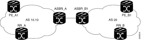
The topology shown in the figure above consists of two PE routers connected across an autonomous system boundary using two ASBRs. Routes are shared within each autonomous system using BGP route reflectors (RRs). (The RRs are included only for the purpose of showing a complete configuration. RRs are not a requirement for the L2VPN Inter-AS Option B configuration.)
The specific configurations for each of the elements in this topology are shown below. The text in bold indicates the additions needed to the standard VPLS Autodiscovery: BGP Based configuration.
PE_A1 Router
mpls ldp discovery targeted-hello accept
mpls label protocol ldp
!
l2 router-id 10.1.1.1
!
l2 pseudowire routing
 terminating-pe tie-breaker
!
l2 vfi vfiA autodiscovery
 vpn id 111
 vpls-id 111:111
 rd 111:111
 route-target 111:111
 no auto-route-target
!
!
interface Loopback0
 ip address 10.1.1.1 255.255.255.255
!
!
interface GigabitEthernet2/0/9
 description AS-10.10-Backbone-LAN
 ip address 10.100.100.1 255.255.255.0
 mpls ip
!
router ospf 10
 network 10.1.1.1 0.0.0.0 area 0
 network 10.100.100.1 0.0.0.0 area 0
!
router bgp 10.10
 bgp asnotation dot
 bgp log-neighbor-changes
 no bgp default ipv4-unicast
 neighbor 10.3.3.3 remote-as 10.10
 neighbor 10.3.3.3 description RR-AS-10.10
 neighbor 10.3.3.3 update-source Loopback0
 !
 address-family ipv4
  no auto-summary
 exit-address-family
 !
 address-family l2vpn vpls
  neighbor 10.3.3.3 activate
  neighbor 10.3.3.3 send-community extended
 exit-address-family
!
mpls ldp router-id Loopback0
!
ASBR_A Router
mpls ldp discovery targeted-hello accept
mpls label protocol ldp
!
!
interface Loopback0
 ip address 10.4.4.4 255.255.255.255
!
interface GigabitEthernet1/10
 description AS-10.10-backbone-Lan
 ip address 10.100.100.4 255.255.255.0
 mpls ip
!
interface GigabitEthernet2/0/1
 description B2B-AS-20-ASBR-B1
 ip address 10.12.1.4 255.255.255.0
 mpls ip
!
router ospf 10
 passive-interface GigabitEthernet1/12
 passive-interface GigabitEthernet2/0/1
 passive-interface GigabitEthernet2/0/2
 network 10.4.4.4 0.0.0.0 area 0
 network 10.100.100.4 0.0.0.0 area 0
 network 10.12.0.0 0.0.255.255 area 0
!
router bgp 10.10
 bgp router-id 10.4.4.4
 bgp asnotation dot
 bgp log-neighbor-changes
 no bgp default route-target filter
 no bgp default ipv4-unicast
 timers bgp 10 30
 neighbor AS20 peer-group
 neighbor AS20 remote-as 20
 neighbor 10.3.3.3 remote-as 10.10
 neighbor 10.3.3.3 update-source Loopback0
 neighbor 10.12.1.6 peer-group AS20
 !
 address-family ipv4
  no auto-summary
 exit-address-family
 !
 address-family l2vpn vpls
  neighbor AS20 send-community extended
  neighbor AS20 next-hop-self
  neighbor 10.3.3.3 activate
  neighbor 10.3.3.3 send-community extended
  neighbor 10.3.3.3 next-hop-self
  neighbor 12.12.1.6 activate
 exit-address-family
!
ip route 10.6.6.6 255.255.255.255 10.12.1.6
ip route 10.9.9.9 255.255.255.255 10.12.3.9
!
mpls ldp router-id Loopback0
!
RR_A Router
interface Loopback0
 ip address 10.3.3.3 255.255.255.255
!
interface Ethernet2/0
 ip address 10.100.100.3 255.255.255.0
 duplex half
!
router ospf 10
 network 10.3.3.3 0.0.0.0 area 0
 network 10.100.100.3 0.0.0.0 area 0
!
router bgp 10.10
 bgp asnotation dot
 bgp log-neighbor-changes
 no bgp default ipv4-unicast
 neighbor rr-client peer-group
 neighbor rr-client remote-as 10.10
 neighbor rr-client update-source Loopback0
 neighbor 10.1.1.1 peer-group rr-client
 neighbor 10.4.4.4 peer-group rr-client
 !
 address-family ipv4
  no auto-summary
 exit-address-family
 !
 address-family l2vpn vpls
  neighbor rr-client send-community extended
  neighbor rr-client route-reflector-client
  neighbor 10.1.1.1 activate
  neighbor 10.4.4.4 activate
 exit-address-family
!
PE_B1 Router
mpls ldp discovery targeted-hello accept
mpls label protocol ldp
!
l2 router-id 10.5.5.5
l2 pseudowire routing
 terminating-pe tie-breaker
l2 vfi vfiA autodiscovery
 vpn id 111
 vpls-id 111:111
 rd 111:111
 route-target 111:111
 no auto-route-target
!
interface Loopback0
 ip address 10.5.5.5 255.255.255.255
!
interface GigabitEthernet2/0/7
 description AS20-Backbone-LAN
 ip address 10.100.100.5 255.255.255.0
 mpls ip
!
router ospf 20
 network 10.5.5.5 0.0.0.0 area 0
 network 10.100.100.5 0.0.0.0 area 0
!
router bgp 20
 bgp router-id 10.5.5.5
 bgp asnotation dot
 bgp log-neighbor-changes
 no bgp default ipv4-unicast
 neighbor 10.8.8.8 remote-as 20
 neighbor 10.8.8.8 update-source Loopback0
 !
 address-family ipv4
  no auto-summary
 exit-address-family
 !
 address-family l2vpn vpls
  neighbor 10.8.8.8 activate
  neighbor 10.8.8.8 send-community extended
 exit-address-family
!
mpls ldp router-id Loopback0
!
ASBR_B1 Router
mpls ldp discovery targeted-hello accept
mpls label protocol ldp
!
l2 router-id 10.6.6.6
l2 pseudowire routing
 terminating-pe tie-breaker
!
interface Loopback0
 ip address 10.6.6.6 255.255.255.255
!
interface Ethernet1/3
 description B2B-AS-10.10-ASBR-A
 ip address 10.12.1.6 255.255.255.0
 duplex half
 mpls ip
!
interface Ethernet2/1
 description AS-20-backbone-Lan
 ip address 10.100.100.6 255.255.255.0
 duplex half
 mpls ip
!
router ospf 20
 passive-interface Ethernet1/3
 network 10.12.1.6 0.0.0.0 area 0
 network 10.6.6.6 0.0.0.0 area 0
 network 10.100.100.6 0.0.0.0 area 0
!
router bgp 20
 bgp router-id 10.6.6.6
 bgp asnotation dot
 bgp log-neighbor-changes
 no bgp default ipv4-unicast
 timers bgp 10 30
 neighbor 10.12.1.4 remote-as 10.10
 neighbor 10.12.1.4 ebgp-multihop 255
 neighbor 10.8.8.8 remote-as 20
 neighbor 10.8.8.8 update-source Loopback0
 !
 address-family ipv4
  no auto-summary
 exit-address-family
 !
 address-family l2vpn vpls
  no bgp default route-target filter
  neighbor 10.12.1.4 activate
  neighbor 10.12.1.4 send-community extended
  neighbor 10.12.1.4 next-hop-self
  neighbor 10.8.8.8 activate
  neighbor 10.8.8.8 send-community extended
  neighbor 10.8.8.8 next-hop-self
 exit-address-family
!
RR_B Router
interface Loopback0
 ip address 10.8.8.8 255.255.255.255
!
interface Ethernet2/1
 ip address 10.100.100.8 255.255.255.0
 duplex half
!
router ospf 20
 network 10.8.8.8 0.0.0.0 area 0
 network 10.100.100.8 0.0.0.0 area 0
!
router bgp 20
 bgp log-neighbor-changes
 no bgp default ipv4-unicast
 neighbor rrc peer-group
 neighbor rrc remote-as 20
 neighbor rrc update-source Loopback0
 neighbor 10.5.5.5 peer-group rrc
 neighbor 10.6.6.6 peer-group rrc
 neighbor 10.9.9.9 peer-group rrc
 neighbor 10.9.9.9 shutdown
 !
 address-family ipv4
  no auto-summary
 exit-address-family
 !
 address-family l2vpn vpls
  neighbor rrc send-community extended
  neighbor rrc route-reflector-client
  neighbor 10.5.5.5 activate
  neighbor 10.6.6.6 activate
  neighbor 10.9.9.9 activate
 exit-address-family
!
Example Sample L2VPN VPLS Inter-AS Option B Configuration using the commands associated with the L2VPN Protocol-Based CLIs feature
The example below is a sample L2VPN VPLS Inter-AS Option B configuration based on the topology shown in the following figure.
The topology shown in the figure above consists of two provider edge ( PE) routers connected across an autonomous system boundary using two ASBRs. Routes are shared within each autonomous system using BGP route reflectors (RRs). (The RRs are included only for the purpose of showing a complete configuration. RRs are not a requirement for the L2VPN Inter-AS Option B configuration.)
The specific configurations for each of the elements in this topology are shown below. The commands highlighted in bold indicate the additions needed to the standard VPLS Autodiscovery: BGP Based configuration.
PE_A1 Router
mpls ldp discovery targeted-hello accept
mpls label protocol ldp
!
l2vpn
 router-id 10.1.1.1
 pseudowire routing
 		terminating-pe tie-breaker
!
l2vpn vfi context vfiA
	vpn id 111
	autodiscovery bgp signaling ldp
 vpls-id 111:111
 rd 111:111
 route-target 111:111
 no auto-route-target
!
!
interface Loopback0
 ip address 10.1.1.1 255.255.255.255
!
!
interface GigabitEthernet2/0/9
 description AS-10.10-Backbone-LAN
 ip address 10.100.100.1 255.255.255.0
 mpls ip
!
router ospf 10
 network 10.1.1.1 0.0.0.0 area 0
 network 10.100.100.1 0.0.0.0 area 0
!
router bgp 10.10
 bgp asnotation dot
 bgp log-neighbor-changes
 no bgp default ipv4-unicast
 neighbor 10.3.3.3 remote-as 10.10
 neighbor 10.3.3.3 description RR-AS-10.10
 neighbor 10.3.3.3 update-source Loopback0
 !
 address-family ipv4
  no auto-summary
 exit-address-family
 !
 address-family l2vpn vpls
  neighbor 10.3.3.3 activate
  neighbor 10.3.3.3 send-community extended
 exit-address-family
!
mpls ldp router-id Loopback0
!
ASBR_A Router
mpls ldp discovery targeted-hello accept
mpls label protocol ldp
!
!
interface Loopback0
 ip address 10.4.4.4 255.255.255.255
!
interface GigabitEthernet1/10
 description AS-10.10-backbone-Lan
 ip address 10.100.100.4 255.255.255.0
 mpls ip
!
interface GigabitEthernet2/0/1
 description B2B-AS-20-ASBR-B1
 ip address 10.12.1.4 255.255.255.0
 mpls ip
!
router ospf 10
 passive-interface GigabitEthernet1/12
 passive-interface GigabitEthernet2/0/1
 passive-interface GigabitEthernet2/0/2
 network 10.4.4.4 0.0.0.0 area 0
 network 10.100.100.4 0.0.0.0 area 0
 network 10.12.0.0 0.0.255.255 area 0
!
router bgp 10.10
 bgp router-id 10.4.4.4
 bgp asnotation dot
 bgp log-neighbor-changes
 no bgp default route-target filter
 no bgp default ipv4-unicast
 timers bgp 10 30
 neighbor AS20 peer-group
 neighbor AS20 remote-as 20
 neighbor 10.3.3.3 remote-as 10.10
 neighbor 10.3.3.3 update-source Loopback0
 neighbor 10.12.1.6 peer-group AS20
 !
 address-family ipv4
  no auto-summary
 exit-address-family
 !
 address-family l2vpn vpls
  neighbor AS20 send-community extended
  neighbor AS20 next-hop-self
  neighbor 10.3.3.3 activate
  neighbor 10.3.3.3 send-community extended
  neighbor 10.3.3.3 next-hop-self
  neighbor 12.12.1.6 activate
 exit-address-family
!
ip route 10.6.6.6 255.255.255.255 10.12.1.6
ip route 10.9.9.9 255.255.255.255 10.12.3.9
!
mpls ldp router-id Loopback0
!
RR_A Router
interface Loopback0
 ip address 10.3.3.3 255.255.255.255
!
interface Ethernet2/0
 ip address 10.100.100.3 255.255.255.0
 duplex half
!
router ospf 10
 network 10.3.3.3 0.0.0.0 area 0
 network 10.100.100.3 0.0.0.0 area 0
!
router bgp 10.10
 bgp asnotation dot
 bgp log-neighbor-changes
 no bgp default ipv4-unicast
 neighbor rr-client peer-group
 neighbor rr-client remote-as 10.10
 neighbor rr-client update-source Loopback0
 neighbor 10.1.1.1 peer-group rr-client
 neighbor 10.4.4.4 peer-group rr-client
 !
 address-family ipv4
  no auto-summary
 exit-address-family
 !
 address-family l2vpn vpls
  neighbor rr-client send-community extended
  neighbor rr-client route-reflector-client
  neighbor 10.1.1.1 activate
  neighbor 10.4.4.4 activate
 exit-address-family
!
PE_B1 Router
mpls ldp discovery targeted-hello accept
mpls label protocol ldp
!
l2vpn
 router-id 10.5.5.5
 pseudowire routing
 	terminating-pe tie-breaker
l2vpn vfi context vfiA
	vpn id 111
	autodiscovery bgp signaling ldp
 vpls-id 111:111
 rd 111:111
 route-target 111:111
 no auto-route-target
!
interface Loopback0
 ip address 10.5.5.5 255.255.255.255
!
interface GigabitEthernet2/0/7
 description AS20-Backbone-LAN
 ip address 10.100.100.5 255.255.255.0
 mpls ip
!
router ospf 20
 network 10.5.5.5 0.0.0.0 area 0
 network 10.100.100.5 0.0.0.0 area 0
!
router bgp 20
 bgp router-id 10.5.5.5
 bgp asnotation dot
 bgp log-neighbor-changes
 no bgp default ipv4-unicast
 neighbor 10.8.8.8 remote-as 20
 neighbor 10.8.8.8 update-source Loopback0
 !
 address-family ipv4
  no auto-summary
 exit-address-family
 !
 address-family l2vpn vpls
  neighbor 10.8.8.8 activate
  neighbor 10.8.8.8 send-community extended
 exit-address-family
!
mpls ldp router-id Loopback0
!
ASBR_B1 Router
mpls ldp discovery targeted-hello accept
mpls label protocol ldp
!
l2vpn
 router-id 10.6.6.6
 pseudowire routing
 	terminating-pe tie-breaker
!
interface Loopback0
 ip address 10.6.6.6 255.255.255.255
!
interface Ethernet1/3
 description B2B-AS-10.10-ASBR-A
 ip address 10.12.1.6 255.255.255.0
 duplex half
 mpls ip
!
interface Ethernet2/1
 description AS-20-backbone-Lan
 ip address 10.100.100.6 255.255.255.0
 duplex half
 mpls ip
!
router ospf 20
 passive-interface Ethernet1/3
 network 10.12.1.6 0.0.0.0 area 0
 network 10.6.6.6 0.0.0.0 area 0
 network 10.100.100.6 0.0.0.0 area 0
!
router bgp 20
 bgp router-id 10.6.6.6
 bgp asnotation dot
 bgp log-neighbor-changes
 no bgp default ipv4-unicast
 timers bgp 10 30
 neighbor 10.12.1.4 remote-as 10.10
 neighbor 10.12.1.4 ebgp-multihop 255
 neighbor 10.8.8.8 remote-as 20
 neighbor 10.8.8.8 update-source Loopback0
 !
 address-family ipv4
  no auto-summary
 exit-address-family
 !
 address-family l2vpn vpls
  no bgp default route-target filter
  neighbor 10.12.1.4 activate
  neighbor 10.12.1.4 send-community extended
  neighbor 10.12.1.4 next-hop-self
  neighbor 10.8.8.8 activate
  neighbor 10.8.8.8 send-community extended
  neighbor 10.8.8.8 next-hop-self
 exit-address-family
!
RR_B Router
interface Loopback0
 ip address 10.8.8.8 255.255.255.255
!
interface Ethernet2/1
 ip address 10.100.100.8 255.255.255.0
 duplex half
!
router ospf 20
 network 10.8.8.8 0.0.0.0 area 0
 network 10.100.100.8 0.0.0.0 area 0
!
router bgp 20
 bgp log-neighbor-changes
 no bgp default ipv4-unicast
 neighbor rrc peer-group
 neighbor rrc remote-as 20
 neighbor rrc update-source Loopback0
 neighbor 10.5.5.5 peer-group rrc
 neighbor 10.6.6.6 peer-group rrc
 neighbor 10.9.9.9 peer-group rrc
 neighbor 10.9.9.9 shutdown
 !
 address-family ipv4
  no auto-summary
 exit-address-family
 !
 address-family l2vpn vpls
  neighbor rrc send-community extended
  neighbor rrc route-reflector-client
  neighbor 10.5.5.5 activate
  neighbor 10.6.6.6 activate
  neighbor 10.9.9.9 activate
 exit-address-family
!
Additional References for L2VPN VPLS Inter-AS Option B
Related Documents
|
Related Topic |
Document Title |
|---|---|
|
Cisco IOS commands |
|
|
MPLS commands |
|
|
IP Routing (BGP) commands |
|
|
Concepts and tasks related to configuring the VPLS Autodiscovery: BGP Based feature. |
VPLS Autodiscovery BGP Based |
|
BGP support for the L2VPN address family |
BGP Support for the L2VPN Address Family |
|
VPLS |
“VPLS Overview” section in the Configuring Multiprotocol Label Switching on the Optical Services Modules document |
|
L2VPN multisegment pseudowires, MPLS OAM support for L2VPN multisegment pseudowires, MPLS OAM support for L2VPN inter-AS option B |
L2VPN Multisegment Pseudowires |
Standards
|
Standard |
Title |
|---|---|
|
No new or modified standards are supported, and support for existing standards has not been modified. |
— |
MIBs
|
MIB |
MIBs Link |
|---|---|
|
No new or modified MIBs are supported, and support for existing standards has not been modified. |
To locate and download MIBs for selected platforms, Cisco software releases, and feature sets, use Cisco MIB Locator found at the following URL: |
RFCs
|
RFC |
Title |
|---|---|
|
RFC 4360 |
BGP Extended Communities Attribute |
|
RFC 4364 |
BGP/MPLS IP Virtual Private Networks (VPNs) |
Technical Assistance
|
Description |
Link |
|---|---|
|
The Cisco Support and Documentation website provides online resources to download documentation, software, and tools. Use these resources to install and configure the software and to troubleshoot and resolve technical issues with Cisco products and technologies. Access to most tools on the Cisco Support and Documentation website requires a Cisco.com user ID and password. |
Feature Information for L2VPN VPLS Inter-AS Option B
The following table provides release information about the feature or features described in this module. This table lists only the software release that introduced support for a given feature in a given software release train. Unless noted otherwise, subsequent releases of that software release train also support that feature.
Use Cisco Feature Navigator to find information about platform support and Cisco software image support. To access Cisco Feature Navigator, go to www.cisco.com/go/cfn. An account on Cisco.com is not required.
|
Feature Name |
Releases |
Feature Information |
|---|---|---|
|
L2VPN VPLS Inter-AS Option B |
15.1(1)S Cisco IOS XE Release 3.8S |
The L2VPN VPLS Inter-AS Option B feature expands the existing features of VPLS autodiscovery to operate across multiple BGP autonomous systems. Using BGP-based autodiscovery as the underlying framework, the L2VPN VPLS Inter-AS Option B features creates a dynamic multisegmented pseudowire configuration between neighboring ASBRs. The following commands were introduced or modified: bgp default route-target filter, debug xconnect, l2 pseudowire routing, show ip bgp neighbors, show mpls forwarding-table, show mpls l2transport vc, show xconnect, switching-point vcid, and terminating-pe tie-breaker. |
Glossary
AGI —Attachment Group Identifier. An identifier common to a group of pseudowires that may be connected.
AII —Attachment individual identifier.
ASBR —Autonomous System Boundary Router.
PE —provider edge router.
NLRI —Network Layer Reachability Information.
SAII —Source Attachment Individual Identifier.
SPE —switching PE.
TAII —Target Attachment Individual Identifier.
TPE —terminating PE.
VFI —virtual forwarding instance. This identifies a group of pseudowires that are associated with a VSI.
VSI —virtual switching instance. This identifies the bridge domain within a single PE. In a single VPLS network, each participating PE has a VSI.
 Feedback