- MPLS Virtual Private Networks
- Multiprotocol BGP MPLS VPN
- MPLS VPN OSPF PE and CE Support
- MPLS VPN Support for EIGRP Between PE and CE
- IPv6 VPN over MPLS
- Assigning an ID Number to an MPLS VPN
- MPLS VPN Half-Duplex VRF
- MPLS VPN Show Running VRF
- MPLS VPN VRF CLI for IPv4 and IPv6 VPNs
- MPLS VPN BGP Local Convergence
- MPLS VPN Route Target Rewrite
- MPLS VPN Per VRF Label
- Multi-VRF Selection Using Policy-Based Routing
- MPLS VPN VRF Selection Using Policy-Based Routing
- VRF Aware System Message Logging
- MPLS VPN 6VPE per VRF Label
- Multi-VRF Support
- BGP Best External
- BGP PIC Edge for IP and MPLS-VPN
- MPLS over GRE
- Dynamic Layer 3 VPNs with Multipoint GRE Tunnels
- MPLS VPN 6VPE Support Over IP Tunnels
Contents
- Multiprotocol BGP MPLS VPN
- Finding Feature Information
- Prerequisites for Multiprotocol BGP MPLS VPN
- Information About Multiprotocol BGP MPLS VPN
- MPLS Virtual Private Network Definition
- How an MPLS Virtual Private Network Works
- How Virtual Routing and Forwarding Tables Work in an MPLS Virtual Private Network
- How VPN Routing Information Is Distributed in an MPLS Virtual Private Network
- BGP Distribution of VPN Routing Information
- Major Components of an MPLS Virtual Private Network
- How to Configure Multiprotocol BGP MPLS VPN
- Configuring Multiprotocol BGP Connectivity on the PE Devices and Route Reflectors
- Troubleshooting Tips
- Configuring BGP as the Routing Protocol Between the PE and CE Devices
- Verifying the Virtual Private Network Configuration
- Verifying Connectivity Between MPLS Virtual Private Network Sites
- Verifying IP Connectivity from CE Device to CE Device Across the MPLS Core
- Verifying That the Local and Remote CE Devices Are in the PE Routing Table
- Configuration Examples for Multiprotocol BGP MPLS VPN
- Example: Configuring an MPLS Virtual Private Network Using BGP
- Additional References
- Feature Information for Multiprotocol BGP MPLS VPN
Multiprotocol BGP MPLS VPN
A Multiprotocol Label Switching (MPLS) virtual private network (VPN) consists of a set of sites that are interconnected by means of an MPLS provider core network. At each site, there are one or more customer edge (CE) devices, which attach to one or more provider edge (PE) devices. PEs use the Multiprotocol-Border Gateway Protocol (MP-BGP) to dynamically communicate with each other.
- Finding Feature Information
- Prerequisites for Multiprotocol BGP MPLS VPN
- Information About Multiprotocol BGP MPLS VPN
- How to Configure Multiprotocol BGP MPLS VPN
- Configuration Examples for Multiprotocol BGP MPLS VPN
- Additional References
- Feature Information for Multiprotocol BGP MPLS VPN
Finding Feature Information
Your software release may not support all the features documented in this module. For the latest caveats and feature information, see Bug Search Tool and the release notes for your platform and software release. To find information about the features documented in this module, and to see a list of the releases in which each feature is supported, see the feature information table at the end of this module.
Use Cisco Feature Navigator to find information about platform support and Cisco software image support. To access Cisco Feature Navigator, go to www.cisco.com/go/cfn. An account on Cisco.com is not required.
Prerequisites for Multiprotocol BGP MPLS VPN
Configure MPLS virtual private networks (VPNs) in the core.
Information About Multiprotocol BGP MPLS VPN
MPLS Virtual Private Network Definition
Before defining a Multiprotocol Label Switching virtual private network (MPLS VPN), you must define a VPN in general. A VPN is:
- An IP-based network delivering private network services over a public infrastructure
- A set of sites that are allowed to communicate with each other privately over the Internet or other public or private networks
Conventional VPNs are created by configuring a full mesh of tunnels or permanent virtual circuits (PVCs) to all sites in a VPN. This type of VPN is not easy to maintain or expand, because adding a new site requires changing each edge device in the VPN.
MPLS-based VPNs are created in Layer 3 and are based on the peer model. The peer model enables the service provider and the customer to exchange Layer 3 routing information. The service provider relays the data between the customer sites without the customer’s involvement.
MPLS VPNs are easier to manage and expand than conventional VPNs. When a new site is added to an MPLS VPN, only the service provider’s edge device that provides services to the customer site needs to be updated.
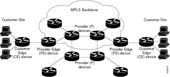
The different parts of the MPLS VPN are described as follows:
- Provider (P) device—Device in the core of the provider network. P devices run MPLS switching, and do not attach VPN labels to routed packets. The MPLS label in each route is assigned by the provider edge (PE) device. VPN labels are used to direct data packets to the correct egress device.
- PE device—Device that attaches the VPN label to incoming packets based on the interface or subinterface on which they are received. A PE device attaches directly to a customer edge (CE) device.
- Customer (C) device—Device in the ISP or enterprise network.
- CE device—Edge device on the network of the ISP that connects to the PE device on the network. A CE device must interface with a PE device.
The figure below shows a basic MPLS VPN.
How an MPLS Virtual Private Network Works
Multiprotocol Label Switching virtual private network (MPLS VPN) functionality is enabled at the edge of an MPLS network. The provider edge (PE) device performs the following:
- Exchanges routing updates with the customer edge (CE) device.
- Translates the CE routing information into VPNv4 routes.
- Exchanges VPNv4 routes with other PE devices through the Multiprotocol Border Gateway Protocol (MP-BGP).
The following sections describe how MPLS VPN works:
- How Virtual Routing and Forwarding Tables Work in an MPLS Virtual Private Network
- How VPN Routing Information Is Distributed in an MPLS Virtual Private Network
- BGP Distribution of VPN Routing Information
How Virtual Routing and Forwarding Tables Work in an MPLS Virtual Private Network
Each virtual private network (VPN) is associated with one or more virtual routing and forwarding (VRF) instances. A VRF defines the VPN membership of a customer site attached to a PE device. A VRF consists of the following components:
- An IP routing table
- A derived Cisco Express Forwarding table
- A set of interfaces that use the forwarding table
- A set of rules and routing protocol parameters that control the information that is included in the routing table
A one-to-one relationship does not necessarily exist between customer sites and VPNs. A site can be a member of multiple VPNs. However, a site can associate with only one VRF. A site’s VRF contains all the routes available to the site from the VPNs of which it is a member.
Packet forwarding information is stored in the IP routing table and the Cisco Express Forwarding table for each VRF. A separate set of routing and Cisco Express Forwarding tables is maintained for each VRF. These tables prevent information from being forwarded outside a VPN, and they also prevent packets that are outside a VPN from being forwarded to a device within the VPN.
How VPN Routing Information Is Distributed in an MPLS Virtual Private Network
The distribution of virtual private network (VPN) routing information is controlled through the use of VPN route target communities, implemented by Border Gateway Protocol (BGP) extended communities. VPN routing information is distributed as follows:
- When a VPN route that is learned from a customer edge (CE) device is injected into BGP, a list of VPN route target extended community attributes is associated with it. Typically the list of route target community extended values is set from an export list of route targets associated with the virtual routing and forwarding (VRF) instance from which the route was learned.
- An import list of route target extended communities is associated with each VRF. The import list defines route target extended community attributes that a route must have in order for the route to be imported into the VRF. For example, if the import list for a particular VRF includes route target extended communities A, B, and C, then any VPN route that carries any of those route target extended communities—A, B, or C—is imported into the VRF.
BGP Distribution of VPN Routing Information
A provider edge (PE) device can learn an IP prefix from the following sources:
- A customer edge (CE) device by static configuration
- A Border Gateway Protocol (BGP) session with the CE device
- A Routing Information Protocol (RIP) exchange with the CE device
The IP prefix is a member of the IPv4 address family. After the PE device learns the IP prefix, the PE converts it into a VPN-IPv4 prefix by combining it with an 8-byte route distinguisher (RD). The generated prefix is a member of the VPN-IPv4 address family. It uniquely identifies the customer address, even if the customer site is using globally nonunique (unregistered private) IP addresses. The route distinguisher used to generate the VPN-IPv4 prefix is specified by a configuration command associated with the virtual routing and forwarding (VRF) instance on the PE device.
BGP distributes reachability information for VPN-IPv4 prefixes for each VPN. BGP communication occurs at two levels:
- Within an IP domains, known as an autonomous system (interior BGP [IBGP])
- Between autonomous systems (external BGP [EBGP])
PE-PE or PE-RR (route reflector) sessions are IBGP sessions, and PE-CE sessions are EBGP sessions. In an Enhanced Interior Gateway Routing Protocol (EIGRP) PE-CE environment, when an EIGRP internal route is redistributed into BGP by one PE, and then back into EIGRP by another PE, the originating router ID for the route is set to the router ID of the second PE, replacing the original internal router ID.
BGP propagates reachability information for VPN-IPv4 prefixes among PE devices by means of the BGP multiprotocol extensions (refer to RFC 2283, Multiprotocol Extensions for BGP-4), which define support for address families other than IPv4. Using the extensions ensures that the routes for a given VPN are learned only by other members of that VPN, enabling members of the VPN to communicate with each other.
Major Components of an MPLS Virtual Private Network
An Multiprotocol Label Switching (MPLS)-based virtual private network (VPN) has three major components:
- VPN route target communities—A VPN route target community is a list of all members of a VPN community. VPN route targets need to be configured for each VPN community member.
- Multiprotocol BGP (MP-BGP) peering of VPN community provider edge (PE) devices—MP-BGP propagates virtual routing and forwarding (VRF) reachability information to all members of a VPN community. MP-BGP peering must be configured on all PE devices within a VPN community.
- MPLS forwarding—MPLS transports all traffic between all VPN community members across a VPN service-provider network.
A one-to-one relationship does not necessarily exist between customer sites and VPNs. A given site can be a member of multiple VPNs. However, a site can associate with only one VRF. A customer-site VRF contains all the routes available to the site from the VPNs of which it is a member.
How to Configure Multiprotocol BGP MPLS VPN
Configuring Multiprotocol BGP Connectivity on the PE Devices and Route Reflectors
1.
enable
2.
configure terminal
3.
router bgp
as-number
4.
no bgp default ipv4-unicast
5.
neighbor {ip-address |
peer-group-name}
remote-as
as-number
6.
neighbor {ip-address |
peer-group-name}
activate
7.
address-family vpnv4 [unicast]
8.
neighbor {ip-address |
peer-group-name}
send-community extended
9.
neighbor {ip-address |
peer-group-name}
activate
10.
end
DETAILED STEPS
Troubleshooting Tips
You can enter a show ip bgp neighbor command to verify that the neighbors are up and running. If this command is not successful, enter a debug ip bgp ip-address events command, where ip-address is the IP address of the neighbor.
Configuring BGP as the Routing Protocol Between the PE and CE Devices
1.
enable
2.
configure terminal
3.
router bgp
as-number
4.
address-family ipv4 [multicast |
unicast |
vrf
vrf-name]
5.
neighbor {ip-address |
peer-group-name}
remote-as
as-number
6.
neighbor {ip-address |
peer-group-name}
activate
7.
exit-address-family
8.
end
DETAILED STEPS
Verifying the Virtual Private Network Configuration
A route distinguisher must be configured for the virtual routing and forwarding (VRF) instance, and Multiprotocol Label Switching (MPLS) must be configured on the interfaces that carry the VRF. Use the show ip vrf command to verify the route distinguisher (RD) and interface that are configured for the VRF.
1.
show ip vrf
DETAILED STEPS
Displays the set of defined VRF instances and associated interfaces. The output also maps the VRF instances to the configured route distinguisher. |
Verifying Connectivity Between MPLS Virtual Private Network Sites
To verify that the local and remote customer edge (CE) devices can communicate across the Multiprotocol Label Switching (MPLS) core, perform the following tasks:
- Verifying IP Connectivity from CE Device to CE Device Across the MPLS Core
- Verifying That the Local and Remote CE Devices Are in the PE Routing Table
Verifying IP Connectivity from CE Device to CE Device Across the MPLS Core
1.
enable
2.
ping [protocol] {host-name |
system-address}
3.
trace [protocol] [destination]
4.
show ip route [ip-address [mask] [longer-prefixes]] |
protocol [process-id]] | [list [access-list-name |
access-list-number]
DETAILED STEPS
Verifying That the Local and Remote CE Devices Are in the PE Routing Table
1.
enable
2.
show ip route vrf
vrf-name [prefix]
3.
show ip cef vrf
vrf-name [ip-prefix]
DETAILED STEPS
Configuration Examples for Multiprotocol BGP MPLS VPN
Example: Configuring an MPLS Virtual Private Network Using BGP
|
PE Configuration |
CE Configuration |
|---|---|
ip vrf vpn1 rd 100:1 route-target export 100:1 route-target import 100:1 ! ip cef mpls ldp router-id Loopback0 force mpls label protocol ldp ! interface Loopback0 ip address 10.0.0.1 255.255.255.255 ! interface FastEthernet0/0/0 ip vrf forwarding vpn1 ip address 192.0.2.3 255.255.255.0 no cdp enable ! interface FastEthernet1/1/0 ip address 192.0.2.2 255.255.255.0 mpls label protocol ldp mpls ip ! router ospf 100 network 10.0.0. 0.0.0.0 area 100 network 192.0.2.1 255.255.255.0 area 100 ! router bgp 100 no synchronization bgp log-neighbor changes neighbor 10.0.0.3 remote-as 100 neighbor 10.0.0.3 update-source Loopback0 no auto-summary ! address-family vpnv4 neighbor 10.0.0.3 activate neighbor 10.0.0.3 send-community extended bgp scan-time import 5 exit-address-family ! address-family ipv4 vrf vpn1 redistribute connected neighbor 198.51.100.1 remote-as 200 neighbor 198.51.100.1 activate neighbor 198.51.100.1 as-override neighbor 198.51.100.1 advertisement-interval 5 no auto-summary no synchronization exit-address-family |
ip cef mpls ldp router-id Loopback0 force mpls label protocol ldp ! interface Loopback0 ip address 10.0.0.9 255.255.255.255 ! interface FastEthernet0/0 ip address 198.51.100.1 255.255.255.0 no cdp enable ! router bgp 200 bgp log-neighbor-changes neighbor 198.51.100.2 remote-as 100 ! address-family ipv4 redistribute connected neighbor 198.51.100.2 activate neighbor 198.51.100.2 advertisement-interval 5 no auto-summary no synchronization exit-address-family |
Additional References
Related Documents
Related Topic |
Document Title |
|---|---|
|
Cisco IOS commands |
|
|
Description of commands associated with MPLS and MPLS applications |
|
|
Configuring MPLS virtual private networks |
“MPLS Virtual Private Networks” module in the MPLS Layer 3 VPNs Configuration Guide |
Standards and RFCs
|
RFC |
Title |
|---|---|
|
RFC 2283 |
Multiprotocol Extensions for BGP-4 |
|
RFC 2547 |
BGP/MPLS VPNs |
Technical Assistance
Description |
Link |
|---|---|
|
The Cisco Support and Documentation website provides online resources to download documentation, software, and tools. Use these resources to install and configure the software and to troubleshoot and resolve technical issues with Cisco products and technologies. Access to most tools on the Cisco Support and Documentation website requires a Cisco.com user ID and password. |
Feature Information for Multiprotocol BGP MPLS VPN
The following table provides release information about the feature or features described in this module. This table lists only the software release that introduced support for a given feature in a given software release train. Unless noted otherwise, subsequent releases of that software release train also support that feature.
Use Cisco Feature Navigator to find information about platform support and Cisco software image support. To access Cisco Feature Navigator, go to www.cisco.com/go/cfn. An account on Cisco.com is not required.
Feature Name |
Releases |
Feature Information |
|---|---|---|
|
Multiprotocol BGP MPLS VPN |
12.0(11)ST 12.2(9)S 12.2(17b)SXA 12.2(27)SBB 12.3(8)T 15.2(1)S Cisco IOS XE Release 2.1 Cisco IOS XE Release 3.5S |
An MPLS VPN consists of a set of sites that are interconnected through the MPLS provider core network. At each site, there are one or more CEs, which attach to one or more PEs. The Multiprotocol BGP MPLS VPN feature allows PEs to use the MP-BGP to dynamically communicate with each other. In Cisco IOS Release 12.0(11)ST, this feature was introduced. In Cisco IOS Release 12.2(9)S, 12.2(17b)SXA, 12.2(27)SBB, 12.3(8)T, and 15.2(1)S, this feature was integrated. In Cisco IOS XE Release 2.1, this feature was implemented on Cisco ASR 1000 Series Routers. In Cisco IOS XE Release 3.5S, support was added for the Cisco ASR 903 Router. No commands were introduced or modified. |