Contents
- Layer 2 Local Switching
- Finding Feature Information
- Prerequisites for Layer 2 Local Switching
- Restrictions for Layer 2 Local Switching
- Information About Layer 2 Local Switching
- Layer 2 Local Switching Overview
- NSF SSO—Local Switching Overview
- Layer 2 Local Switching Applications
- How to Configure Layer 2 Local Switching
- Configuring Ethernet VLAN Same-Port Switching
- Configuring Ethernet Port Mode to Ethernet VLAN Local Switching
- Configuring ATM-to-ATM PVC Local Switching and Same-Port Switching
- Configuring ATM-to-ATM PVP Local Switching
- Configuring ATM PVP Same-Port Switching
- Configuring Frame Relay-to-Frame Relay Local Switching
- Verifying Layer 2 Local Switching
- Verifying Layer 2 Local Switching Configuration
- Verifying the NSF SSO Local Switching Configuration
- Troubleshooting Tips
- Configuration Examples for Layer 2 Local Switching
- Example: Configuring Ethernet VLAN Same-Port Switching
- Example: Configuring NSF SSO Ethernet Port Mode to Ethernet VLAN Local Switching
- Example: Configuring ATM-to-ATM Local Switching
- Example: Configuring ATM PVC Same-Port Switching
- Example: Configuring ATM PVP Same-Port Switching
- Example: Configuring Frame Relay-to-Frame Relay Local Switching
- Additional References
- Feature Information for Layer 2 Local Switching
Layer 2 Local Switching
The Layer 2 Local Switching feature allows you to switch Layer 2 data in two ways:
Between two interfaces on the same router
Between two circuits on the same interface port, which is called same-port switching
The following interface-to-interface switching combinations are supported by this feature:
ATM to ATM
ATM to Ethernet
Ethernet/Ethernet VLAN to Ethernet/Ethernet VLAN
-
Frame Relay to Frame Relay
The following same-port switching features are supported:
- Finding Feature Information
- Prerequisites for Layer 2 Local Switching
- Restrictions for Layer 2 Local Switching
- Information About Layer 2 Local Switching
- How to Configure Layer 2 Local Switching
- Configuration Examples for Layer 2 Local Switching
- Additional References
- Feature Information for Layer 2 Local Switching
Finding Feature Information
Your software release may not support all the features documented in this module. For the latest caveats and feature information, see Bug Search Tool and the release notes for your platform and software release. To find information about the features documented in this module, and to see a list of the releases in which each feature is supported, see the feature information table at the end of this module.
Use Cisco Feature Navigator to find information about platform support and Cisco software image support. To access Cisco Feature Navigator, go to www.cisco.com/go/cfn. An account on Cisco.com is not required.
Prerequisites for Layer 2 Local Switching
You must enable Cisco Express Forwarding for the Cisco ASR 1000 Series Aggregation Services Router.
Restrictions for Layer 2 Local Switching
Information About Layer 2 Local Switching
- Layer 2 Local Switching Overview
- NSF SSO—Local Switching Overview
- Layer 2 Local Switching Applications
Layer 2 Local Switching Overview
Local switching allows you to switch Layer 2 data between two interfaces of the same type (for example, Ethernet to Ethernet or Frame Relay to Frame Relay) or between interfaces of different types (for example, Ethernet VLAN to Ethernet VLAN or Ethernet to Ethernet VLAN) on the same router. The interfaces can be on the same line card or on two different cards. During these kinds of switching, the Layer 2 address is used, not the Layer 3 address.
Additionally, same-port local switching allows you to switch Layer 2 data between two circuits on the same interface.
NSF SSO—Local Switching Overview
Nonstop forwarding (NSF) and stateful switchover (SSO) improve the availability of the network by providing redundant Route Processors and checkpointing of data to ensure minimal packet loss when the primary Route Processor goes down. NSF/SSO support is available for the following locally switched attachment circuits:
Layer 2 Local Switching Applications
Incumbent local exchange carriers (ILECs) that use an interexchange carrier (IXC) to carry traffic between two local exchange carriers can use the Layer 2 Local Switching feature. Telecom regulations require the ILECs to pay the IXCs to carry that traffic. At times, the ILECs cannot terminate customer connections that are in different local access and transport areas (LATAs). In other cases, customer connections terminate in the same LATA, which may also be on the same router.
For example, company A has more than 50 LATAs across the country and uses three routers for each LATA. Company A uses companies B and C to carry traffic between local exchange carriers. Local switching of Layer 2 frames on the same router might be required.
Similarly, if a router is using, for example, a channelized interface, it might need to switch incoming and outgoing traffic across two logical interfaces that reside on a single physical port. The same-port local switching feature addresses that implementation.
The figure below shows a network that uses local switching for both Frame Relay to Frame Relay and ATM to Frame Relay local switching.

How to Configure Layer 2 Local Switching
- Configuring Ethernet VLAN Same-Port Switching
- Configuring Ethernet Port Mode to Ethernet VLAN Local Switching
- Configuring ATM-to-ATM PVC Local Switching and Same-Port Switching
- Configuring ATM-to-ATM PVP Local Switching
- Configuring ATM PVP Same-Port Switching
- Configuring Frame Relay-to-Frame Relay Local Switching
- Verifying Layer 2 Local Switching
Configuring Ethernet VLAN Same-Port Switching
Perform this task to configure Ethernet VLAN same-port switching.
1.
enable
2.
configure
terminal
3.
interface
fastethernet
slot
/
port
.
subinterface-number
4.
encapsulation
dot1q
vlan-id
5.
exit
6.
interface
fastethernet
slot
/
port
.
subinterface-number
7.
encapsulation
dot1q
vlan-id
8.
exit
9.
connect
connection-name
type
number
type
number
DETAILED STEPS
Configuring Ethernet Port Mode to Ethernet VLAN Local Switching
Perform this task to configure local switching for Ethernet (port mode) to Ethernet VLAN.
1.
enable
2.
configure
terminal
3.
interface
fastethernet
slot
/
subslot
/
port
4.
interface
fastethernet
slot
/
port
/
subinterface-number
5.
encapsulation
dot1q
vlan-id
6.
exit
7.
connect
connection-name
type
number
type
number
DETAILED STEPS
Configuring ATM-to-ATM PVC Local Switching and Same-Port Switching
You can configure local switching for both ATM AAL5 and ATM AAL0 encapsulation types.
Creating the ATM PVC is not required. If you do not create a PVC, one is created for you. For ATM-to-ATM local switching, the autoprovisioned PVC is given the default encapsulation type AAL0 cell relay.
1.
enable
2.
configure
terminal
3.
interface
atm
slot
/
port
4.
pvc
vpi
/
vci
l2transport
5.
encapsulation
layer-type
6.
exit
7.
exit
8.
connect
connection-name
interface
pvc
interface
pvc
DETAILED STEPS
Configuring ATM-to-ATM PVP Local Switching
Perform this task to configure ATM-to-ATM PVP local switching.
Starting with Cisco IOS Release 12.0(30)S, you can configure same-port switching, as detailed in the Configuring ATM PVP Same-Port Switching.
1.
enable
2.
configure
terminal
3.
interface
atm
slot/port
4.
atm
pvp
vpi
l2transport
5.
exit
6.
exit
7.
connect
connection-name
interface
pvp
interface
pvp
DETAILED STEPS
Configuring ATM PVP Same-Port Switching
Perform this task to configure ATM PVP switching on an ATM interface.
1.
enable
2.
configure
terminal
3.
interface
atm
slot
/
subslot
/
port
4.
atm
pvp
vpi
l2transport
5.
exit
6.
exit
7.
connect
connection-name
interface
pvp
interface
pvp
DETAILED STEPS
Configuring Frame Relay-to-Frame Relay Local Switching
For information about Frame Relay-to-Frame Relay local switching, see the Distributed Frame Relay Switching feature module.
1.
enable
2.
configure
terminal
3.
ip
cef
distributed
4.
frame-relay
switching
5.
interface
type
number
6.
encapsulation
frame-relay
[cisco |
ietf]
7.
frame-relay
interface-dlci
dlci
switched
8.
exit
9.
exit
10.
connect
connection-name
interface
dlci
interface
dlci
DETAILED STEPS
Verifying Layer 2 Local Switching
- Verifying Layer 2 Local Switching Configuration
- Verifying the NSF SSO Local Switching Configuration
- Troubleshooting Tips
Verifying Layer 2 Local Switching Configuration
To verify configuration of the Layer 2 local switching feature, use the show connection command on the provider edge (PE) router.
1.
show
connection
[all | element | id id | name name | port port]
DETAILED STEPS
The show connectioncommand displays the local connection between a Gigabit Ethernet interface and another local Gigabit Ethernet interface: Example: Router# show connection name ethconn1 Connection: 1 - ethconn1 Current State: UP Segment 1: GigabitEthernet0/0/0.1 up Segment 2: GigabitEthernet0/0/0.2 up |
Verifying the NSF SSO Local Switching Configuration
Layer 2 local switching provides NSF/SSO support for Local Switching of the following attachment circuits on the same router:
For information about configuring NSF/SSO on the Route Processors, see the " Stateful Switchover " module in the Cisco IOS XE High Availability Configuration Guide . Perform this task to verify that the NSF/SSO: Layer 2 Local Switching feature is working correctly.
1.
ping
2.
redundancy
force-switchover
3.
show
connection
all
4.
ping
DETAILED STEPS
Troubleshooting Tips
You can troubleshoot Layer 2 local switching using the following commands on the PE router:
debug conn
show connection
Configuration Examples for Layer 2 Local Switching
- Example: Configuring Ethernet VLAN Same-Port Switching
- Example: Configuring NSF SSO Ethernet Port Mode to Ethernet VLAN Local Switching
- Example: Configuring ATM-to-ATM Local Switching
- Example: Configuring ATM PVC Same-Port Switching
- Example: Configuring ATM PVP Same-Port Switching
- Example: Configuring Frame Relay-to-Frame Relay Local Switching
Example: Configuring Ethernet VLAN Same-Port Switching
The following example shows same-port switching between two VLANs on one Ethernet interface:
interface fastethernet 0/0.1
 encapsulation dot1q 1
interface fastethernet 0/0.2
 encapsulation dot1q 2
connect conn FastEthernet 0/0.1 FastEthernet 0/0.2
Example: Configuring NSF SSO Ethernet Port Mode to Ethernet VLAN Local Switching
The following configuration uses the network topology shown in the figure below.
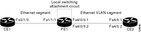
The following example shows the configuration of the CE interfaces to connect to the PE1 router:
|
CE1 |
CE2 |
|---|---|
ip routing ! interface fa3/1/0 description: connection to PE fa1/1/1 no shutdown ip address 10.1.1.1 255.255.255.0 |
ip routing ! interface fa4/0 no shutdown ! interface fa4/0.1 description: connection to PE1 fa6/0/0.1 encapsulation dot1Q 10 ip address 10.1.1.2 255.255.255.0 ! interface fa4/0.2 description - connection to PE1 fa6/0/0.2 encapsulation dot1Q 20 ip address 172.16.1.2 255.255.255.0 |
The following example shows the configuration of the PE1 router with NSF/SSO and the PE interfaces to the CE routers:
PE1
redundancy
no keepalive-enable
mode sso
!
!
ip routing
ip cef distributed
!
interface fa1/1/1
description - connection to CE1 fa3/1/0
no shutdown
no ip address
!
!
interface fa6/0/0
no shutdown
no ip address
!
interface fa6/0/0.1
description - connection to CE2 fa4/0.1
encapsulation dot1Q 10
no ip address
!
interface fa6/0/0.2
description - connection to CE2 fa4/0.2
encapsulation dot1Q 20
no ip address
Example: Configuring ATM-to-ATM Local Switching
The following example shows local switching on ATM interfaces configured for AAL5:
interface atm1/0/0
 pvc 0/100 l2transport
 encapsulation aal5
interface atm2/0/0
 pvc 0/100 l2transport
 encapsulation aal5
connect aal5-conn atm1/0/0 0/100 atm2/0/0 0/100
Example: Configuring ATM PVC Same-Port Switching
The following example shows same-port switching between two PVCs on one ATM interface:
interface atm1/0/0
 pvc 0/100 l2transport
 encapsulation aal5
 pvc 0/200 l2transport
 encapsulation aal5
connect conn atm1/0/0 0/100 atm1/0/0 0/200
Example: Configuring ATM PVP Same-Port Switching
The following example shows same-port switching between two PVPs on one ATM interface:
interface atm1/0/0
 atm pvp 100 l2transport
 atm pvp 200 l2transport
connect conn atm1/0/0 100 atm1/0/0 200
Example: Configuring Frame Relay-to-Frame Relay Local Switching
The following example shows serial interfaces configured for Frame Relay. The connect command allows local switching between these two interfaces.
frame-relay switching
ip cef distributed
interface serial3/0/0
 encapsulation frame-relay
 frame-relay interface-dlci 100 switched
 frame-relay intf-type dce
interface serial3/1/0
 encapsulation frame-relay ietf
 frame-relay interface-dlci 200 switched
 frame-relay intf-type dce
connect fr-con serial3/0/0 100 serial3/1/0 200
Additional References
Related Documents
|
Related Topic |
Document Title |
|---|---|
|
Cisco IOS commands |
|
|
WAN Commands |
Cisco IOS Wide-Area Networking Command Reference |
|
Stateful switchover configuration information |
"Stateful Switchover " module in the Cisco IOS XE High Availability Configuration Guide |
Standards
|
Standard |
Title |
|---|---|
|
draft-ietf-l2tpext-l2tp-base-03.txt |
Layer Two Tunneling Protocol (Version 3) 'L2TPv3' |
|
draft-martini-l2circuit-trans-mpls-09.txt |
Transport of Layer 2 Frames Over MPLS |
|
draft-martini-l2circuit-encap-mpls-04.txt |
Encapsulation Methods for Transport of Layer 2 Frames Over IP and MPLS Networks |
|
draft-ietf-ppvpn-l2vpn-00.txt |
An Architecture for L2VPNs |
MIBs
|
MIB |
MIBs Link |
|---|---|
|
None |
To locate and download MIBs for selected platforms, Cisco IOS XE software releases, and feature sets, use Cisco MIB Locator found at the following URL: |
RFCs
|
RFC |
Title |
|---|---|
|
None |
-- |
Technical Assistance
|
Description |
Link |
|---|---|
|
The Cisco Support and Documentation website provides online resources to download documentation, software, and tools. Use these resources to install and configure the software and to troubleshoot and resolve technical issues with Cisco products and technologies. Access to most tools on the Cisco Support and Documentation website requires a Cisco.com user ID and password. |
Feature Information for Layer 2 Local Switching
The following table provides release information about the feature or features described in this module. This table lists only the software release that introduced support for a given feature in a given software release train. Unless noted otherwise, subsequent releases of that software release train also support that feature.
Use Cisco Feature Navigator to find information about platform support and Cisco software image support. To access Cisco Feature Navigator, go to . An account on Cisco.com is not required.|
Feature Name |
Releases |
Feature Information |
|---|---|---|
|
Layer 2 Local Switching |
Cisco IOS XE Release 2.5 |
The Layer 2 Local Switching feature allows you to switch Layer 2 data between two interfaces on the same router, and in some cases to switch Layer 2 data between two circuits on the same interface port. The following commands were introduced or modified: connect (L2VPN local switching), show connection. |
|
Layer 2 Local Switching - ATM to ATM |
Cisco IOS XE Release 3.3S |
In Cisco IOS XE Release 3.3S, this feature was introduced on the Cisco ASR 1000 Series Aggregation Services Routers. The following commands were introduced or modified: connect (L2VPN local switching), show connection. |
Layer 2 Local Switching - Frame Relay to Frame Relay |
Cisco IOS XE Release 3.9S |
In Cisco IOS XE Release 3.9S, this feature was introduced on the Cisco ISR 4400 Series Routers. |