- Contents
- Overview
- Supported Platforms
- Supported MIBs, and RFCs
- Safety Overview
- Software Requirements
- Hardware Requirements
- Required Tools
- Installing and Removing the PSD
Cisco Persistent Storage Device Module Installation and Configuration Guide
WS-SVC-PSD-1
This publication describes how to install and configure the Cisco Persistent Storage Device (PSD) on the Catalyst 6500 series switch. See the "Related Documentation" section for more information about software configuration for the switch.

Note ![]() For translations of the warnings in this publication, see the "Safety Overview" section and refer to the Regulatory Compliance and Safety Information for the Catalyst 6500 series switches.
For translations of the warnings in this publication, see the "Safety Overview" section and refer to the Regulatory Compliance and Safety Information for the Catalyst 6500 series switches.
Contents
This publication consists of these sections:
•![]() Installing and Removing the PSD
Installing and Removing the PSD
•![]() Standards Compliance Specifications
Standards Compliance Specifications
Overview
This section describes the Catalyst 6500 and 7600 series PSD, how it operates, and how to manage it, and includes these sections:
•![]() Understanding How the PSD Works
Understanding How the PSD Works
•![]() Configuring and Managing the PSD
Configuring and Managing the PSD
Understanding How the PSD Works
The Cisco Persistent Storage Device (PSD) provides persistent storage capabilities to Cisco clients, and allows the clients to store data on the PSD's internal hard drive. Release 1.x provides content data records (CDR) backup capabilities for Cisco's Content Services Gateway (CSG). Release 2.0 adds CDR backup capabilities for the Cisco Gateway GPRS Serving Node (GGSN).
A single PSD can support both CSGs and GGSNs. The number of CSGs and GGSNs that can be supported by a single PSD is limited by the traffic load generated by each, as well as the duration of storage that you desire.
Storage and Retrieval on the PSD
Under normal conditions, a Cisco client will send content data records to Mediation Partners' servers. If those servers become unreachable—for any reason—records are then sent to the PSD for safekeeping until contact is re-established with the Charging Gateway (CG). Once contact is re-established, the client retrieves the records from the PSD, and forwards them to the CG.
Storage
Under normal conditions, the PSD provides backup capabilities when necessary—for example, during network outages. The PSD stores the payload from the packet in a queue, and is unaware of the content or format of that data, so that the data can be retrieved exactly as it was sent.
Retrieval
Once the client has determined that it's regular data server is reachable, you issue a CLI command to request that the data files for a given data store be transferred using FTP to a specified URL. You can also restore the configuration to a previously saved version that includes all the IP and application related configuration files. And, you can issue another CLI command to delete transferred files.
Note ![]() The GGSN requires all client Charging Gateways (CG) to send a Node Alive request when they initially startup. The GGSN uses receipt of the Node Alive as an indicator that a CG is now available. Therefore, the GTP' interface on the PSD supports sending Node Alive requests in order to properly support the GGSN.
The GGSN requires all client Charging Gateways (CG) to send a Node Alive request when they initially startup. The GGSN uses receipt of the Node Alive as an indicator that a CG is now available. Therefore, the GTP' interface on the PSD supports sending Node Alive requests in order to properly support the GGSN.
Datastores
Datastores are locations for a particular client that map to the PSD's hard drive. In this release, you can create up to twenty (20) separate datastores and name them. Twenty datatstores support four MWAM cards in a single chassis with each running five client images, and allows each client to have its own data store. Additionally, datastores have access lists that you can configure to allow specific clients to read and write to specific datastores. Currently, the number of accessors is limited to two (2). The data store access list contains an optional port number in addition to the IP address for each accessor.
When the preferred destination for data becomes unavailable, or during any network outage, data is sent to the PSD and is stored on a "first come, first served" basis. The maximum record storage capability of the PSD is 37 gigabytes, and is allocated as needed.
Format of Datastore Data Files
A data store is comprised of one or more data files. Each data file is composed of multiple records that are constructed of various management related fields, data, and an end-of-record (EOR) indicator. If you need to retrieve data files using FTP (files that are usually corrupt), you will need to understand the format of the data. The following is the format for each record written to a data file:
Flag |
CRC |
Data Length |
Data |
EOR |
•![]() The "Flag" is a 4-byte integer value that indicates the status of the record. This value is used as a 32 bit mask with individual bits having specific meanings. The following bits have assigned values with bit 1 being the least significant (right most bit):
The "Flag" is a 4-byte integer value that indicates the status of the record. This value is used as a 32 bit mask with individual bits having specific meanings. The following bits have assigned values with bit 1 being the least significant (right most bit):
–![]() Bit 1: Record written—a value of "1" indicates that the record has been completely written to file. A value of "0" indicates that it is an incomplete record, and is probably corrupt.
Bit 1: Record written—a value of "1" indicates that the record has been completely written to file. A value of "0" indicates that it is an incomplete record, and is probably corrupt.
–![]() Bit 2: Record acknowledged—a value of "1" indicates that the client has acknowledged that it read the record. A value of "0" indicates that the client has not acknowledged that it read the record.
Bit 2: Record acknowledged—a value of "1" indicates that the client has acknowledged that it read the record. A value of "0" indicates that the client has not acknowledged that it read the record.
–![]() Bit 3:CRC Present—a value of "1" indicates that the Circular Redundancy Check (CRC) field contains a CRC value for the data in this record. A value of "0" indicates the CRC field can be ignored when validating the record.
Bit 3:CRC Present—a value of "1" indicates that the Circular Redundancy Check (CRC) field contains a CRC value for the data in this record. A value of "0" indicates the CRC field can be ignored when validating the record.
•![]() The "CRC" is a 4-byte integer value representing a CRC-32 value.
The "CRC" is a 4-byte integer value representing a CRC-32 value.
•![]() The "Data Length" is a 4-byte integer value representing the length of the Data field.
The "Data Length" is a 4-byte integer value representing the length of the Data field.
•![]() The "Data" is the data the client device has written to the data store.
The "Data" is the data the client device has written to the data store.
•![]() The "EOR" is a one-byte value of 0xFF that indicates the end-of-record.
The "EOR" is a one-byte value of 0xFF that indicates the end-of-record.
An End-of-File (EOF) marker follows the last record in a file. This marker is a 4 byte field with a value of 0xFFFFFFFF.
Data files are named with a numeric prefix and a file extension of ".data" (for example, 000000001.data).
Platform and Network Planning
In release 1.x and above, the PSD is implemented as a single linecard that sits in a Catalyst 6500 or 7600 chassis.
The PSD hardware supports the following features:
•![]() Critical data backup from single failures
Critical data backup from single failures
•![]() Internal 40 GB hard disk, with a maximum storage capability of 37 GB.
Internal 40 GB hard disk, with a maximum storage capability of 37 GB.
•![]() Single module in Catalyst 65xx or 76xx chassis
Single module in Catalyst 65xx or 76xx chassis
The typical configuration will be a chassis with up to twenty active co-resident clients and a single PSD serving those clients. The number of PSDs required is determined based on expected network traffic, and the corresponding records that Cisco clients would generate (for example, billing records from a CSG).
Cisco recommends that you consult your sales engineer for specific network planning. You can, however, get a general idea of how many PSDs your network requires by using the following criteria.
To determine the number of PSDs you need, take the maximum value of the following variables:
•![]() Number of Clients ÷ the maximum number of Datastores per PSD, or
Number of Clients ÷ the maximum number of Datastores per PSD, or
•![]() Client transmit data rate ÷ the PSD's maximum receive data rate, or
Client transmit data rate ÷ the PSD's maximum receive data rate, or
•![]() (Hours of storage × client transmit data rate) ÷ the max storage per PSD.
(Hours of storage × client transmit data rate) ÷ the max storage per PSD.
Additionally, the following values will be useful to you for network planning:
•![]() Max datastores per PSD = 20
Max datastores per PSD = 20
•![]() Client transmit rate = 750MB per hour (actual rates will vary)
Client transmit rate = 750MB per hour (actual rates will vary)
•![]() PSD's max receive rate = 640MB per hour
PSD's max receive rate = 640MB per hour
•![]() Max PSD storage capacity = 37GB
Max PSD storage capacity = 37GB
Configuring and Managing the PSD
The PSD is configured and managed by sessioning to the PSD module from IOS on the Supervisor card, or with Telnet when Telnet is enabled. The PSD is then configured using a CLI much like IOS. In addition to a number of administrative and troubleshooting commands on the PSD, there are basic configuration commands that allow you to create and manage datastores on the PSD, and to assign clients that may access (read/write) those datastores. Typically, you would configure a datastore for each client, or pair of redundant clients.
Additionally, you must configure the clients to inform them of the location and presence of a PSD.
New Features in Release 2.0
The following features are new for the PSD Release 2.0:
•![]() The configuration save command is introduced to save and store PSD configuration files to a specified FTP URL.
The configuration save command is introduced to save and store PSD configuration files to a specified FTP URL.
•![]() The datatstore transfer command is introduced to transfer PSD configuration files to a specified FTP URL, and to optionally delete them.
The datatstore transfer command is introduced to transfer PSD configuration files to a specified FTP URL, and to optionally delete them.
•![]() The configuration restore command is introduced to restore a PSD using the saved configuration files from the specified FTP URL.
The configuration restore command is introduced to restore a PSD using the saved configuration files from the specified FTP URL.
•![]() The datastore purge command allows you to delete sets of files.
The datastore purge command allows you to delete sets of files.
•![]() The maximum number of data stores is increased to 20 (the equivalent to 4 MWAMs of GGSNs).
The maximum number of data stores is increased to 20 (the equivalent to 4 MWAMs of GGSNs).
•![]() The same PSD can be shared by a CSG and a GGSN.
The same PSD can be shared by a CSG and a GGSN.
PSD Features in Release 1.1(1)
These are the features for the Cisco PSD software release 1.1(1)
•![]() Support for full capacity of the existing 40GB Hard drive, providing up to 37GB of record storage.
Support for full capacity of the existing 40GB Hard drive, providing up to 37GB of record storage.
PSD Features in Release 1.0(1)
These are the features for the PSD in software release 1.0(1):
•![]() The PSD supports up to 3 clients.
The PSD supports up to 3 clients.
•![]() Call Data Record Backup (CDRB) function to support the Cisco CSG.
Call Data Record Backup (CDRB) function to support the Cisco CSG.
•![]() Data packets (CDRs) are retrievable in the order they were stored on the PSD.
Data packets (CDRs) are retrievable in the order they were stored on the PSD.
Supported Platforms
•![]() Catalyst 6500 Switch running IOS
Catalyst 6500 Switch running IOS
•![]() Cisco 7600 Internet Router running IOS
Cisco 7600 Internet Router running IOS
Finding Support Information for Platforms and Cisco IOS Software Images
Use Cisco Feature Navigator to find information about platform support and Cisco IOS software image support. Access Cisco Feature Navigator at http://www.cisco.com/go/fn. You must have an account on Cisco.com. If you do not have an account or have forgotten your username or password, click Cancel at the login dialog box and follow the instructions that appear.
Supported MIBs, and RFCs
The following sections provide information about the MIBs and RFCs that are supported on the PSD:
MIBs
•![]() IF-MIB
IF-MIB
•![]() MIB-2
MIB-2
•![]() HOST-RESOURCE-MIB
HOST-RESOURCE-MIB
RFCs
•![]() RFC1229—Manage network interfaces
RFC1229—Manage network interfaces
•![]() RFC1213—Standard network device management
RFC1213—Standard network device management
•![]() RFC1514, RFC2790—Detailed system resources management that provides the ability to see all processes and their utilization. Disk partitions are visible and disk usage is available. You need net-snmp agent for this support.
RFC1514, RFC2790—Detailed system resources management that provides the ability to see all processes and their utilization. Disk partitions are visible and disk usage is available. You need net-snmp agent for this support.
Front Panel Description
The PSD front panel (see Figure 1-1) includes a STATUS LED and SHUTDOWN button.
Figure 1-1 Persistent Storage Device Module

STATUS LED
The STATUS LED indicates the operating states of the PSD. Table 1-1 describes the LED operation.
SHUTDOWN Button
Push the "shutdown" buttom on the faceplate of the PSD card, then wait for the faceplate LED to change from green to amber.

To avoid corrupting the PSD hard disk, you must correctly shut down the PSD before you remove it from the chassis or disconnect the power. This shutdown procedure is normally initiated by commands entered at the Supervisor engine CLI prompt or the PSD CLI prompt.
If the PSD fails to respond to these commands properly, you can use the SHUTDOWN button on the front panel to initiate the shutdown procedure.
The shutdown procedure may require several minutes. The STATUS LED turns orange when the PSD shuts down.
Conditions That Require Shutdown of a PSD Card
Before you perform any of the following operations, you should shut down the PSD:
•![]() Physically remove the PSD cards from Cat6500/7600 slots.
Physically remove the PSD cards from Cat6500/7600 slots.
•![]() Manually switch the power off on the Cisco Catalyst 6500 or 7600 boxes.
Manually switch the power off on the Cisco Catalyst 6500 or 7600 boxes.
•![]() Any other conditions that causes a sudden power interruption of the chassis.
Any other conditions that causes a sudden power interruption of the chassis.
Methods to Shutdown the PSD Card
Use one of the following methods to gracefully power down the PSD cards:
•![]() In SUP configuration mode, issue the no power enable module mod # command.
In SUP configuration mode, issue the no power enable module mod # command.
•![]() In SUP exec mode, issue the hw-module module mod # shutdown command.
In SUP exec mode, issue the hw-module module mod # shutdown command.
•![]() Push the "shutdown" buttom on the faceplate of the PSD card.
Push the "shutdown" buttom on the faceplate of the PSD card.
•![]() A software reload of the Supervisor IOS using the reload command in the Supervisor CLI (the whole box reloads).
A software reload of the Supervisor IOS using the reload command in the Supervisor CLI (the whole box reloads).
Note ![]() If you use any other method to shutdown the PSD than the "shutdown" button, you must verify that the PSD is completely shutdown by looking at the state using the show module n command.
If you use any other method to shutdown the PSD than the "shutdown" button, you must verify that the PSD is completely shutdown by looking at the state using the show module n command.
routert#sho mod 5
> Mod Ports Card Type Model Serial No.
> --- ----- -------------------------------------- ------------------ -----------
> 5 3 Persistent Storage Device WS-SVC-PSD-1 SAD10280323
>
> Mod MAC addresses Hw Fw Sw Status
> --- ---------------------------------- ------ ------------ ------------ -------
> 5 0018.197e.22c2 to 0018.197e.22c9 3.0 7.2(1) 1.1(3) ShutDown
Note ![]() Alternately, you can wait for the text "SP: PC shutdown completed for module 5" to appear on the console.
Alternately, you can wait for the text "SP: PC shutdown completed for module 5" to appear on the console.
Specifications
Table 1-2 describes the specifications for the PSD.
Safety Overview
Safety warnings appear throughout this document in procedures that may harm you if performed incorrectly.
For additional safety information, refer to documents listed in the "Related Documentation" section.

Warning ![]() This warning symbol means danger. You are in a situation that could cause bodily injury. Before you work on any equipment, be aware of the hazards involved with electrical circuitry and be familiar with standard practices for preventing accidents. To see translations of the warnings that appear in this publication, refer to the Regulatory Compliance and Safety Information document that accompanied this device.
This warning symbol means danger. You are in a situation that could cause bodily injury. Before you work on any equipment, be aware of the hazards involved with electrical circuitry and be familiar with standard practices for preventing accidents. To see translations of the warnings that appear in this publication, refer to the Regulatory Compliance and Safety Information document that accompanied this device.
Warning ![]() Waarschuwing Dit waarschuwingssymbool betekent gevaar. U verkeert in een situatie die lichamelijk letsel kan veroorzaken. Voordat u aan enige apparatuur gaat werken, dient u zich bewust te zijn van de bij elektrische schakelingen betrokken risico's en dient u op de hoogte te zijn van standaard maatregelen om ongelukken te voorkomen. Voor vertalingen van de waarschuwingen die in deze publicatie verschijnen, kunt u het document Regulatory Compliance and Safety Information (Informatie over naleving van veiligheids- en andere voorschriften) raadplegen dat bij dit toestel is ingesloten.
Waarschuwing Dit waarschuwingssymbool betekent gevaar. U verkeert in een situatie die lichamelijk letsel kan veroorzaken. Voordat u aan enige apparatuur gaat werken, dient u zich bewust te zijn van de bij elektrische schakelingen betrokken risico's en dient u op de hoogte te zijn van standaard maatregelen om ongelukken te voorkomen. Voor vertalingen van de waarschuwingen die in deze publicatie verschijnen, kunt u het document Regulatory Compliance and Safety Information (Informatie over naleving van veiligheids- en andere voorschriften) raadplegen dat bij dit toestel is ingesloten.
Warning ![]() Varoitus Tämä varoitusmerkki merkitsee vaaraa. Olet tilanteessa, joka voi johtaa ruumiinvammaan. Ennen kuin työskentelet minkään laitteiston parissa, ota selvää sähkökytkentöihin liittyvistä vaaroista ja tavanomaisista onnettomuuksien ehkäisykeinoista. Tässä julkaisussa esiintyvien varoitusten käännökset löydät laitteen mukana olevasta Regulatory Compliance and Safety Information -kirjasesta (määräysten noudattaminen ja tietoa turvallisuudesta).
Varoitus Tämä varoitusmerkki merkitsee vaaraa. Olet tilanteessa, joka voi johtaa ruumiinvammaan. Ennen kuin työskentelet minkään laitteiston parissa, ota selvää sähkökytkentöihin liittyvistä vaaroista ja tavanomaisista onnettomuuksien ehkäisykeinoista. Tässä julkaisussa esiintyvien varoitusten käännökset löydät laitteen mukana olevasta Regulatory Compliance and Safety Information -kirjasesta (määräysten noudattaminen ja tietoa turvallisuudesta).
Warning ![]() Attention Ce symbole d'avertissement indique un danger. Vous vous trouvez dans une situation pouvant causer des blessures ou des dommages corporels. Avant de travailler sur un équipement, soyez conscient des dangers posés par les circuits électriques et familiarisez-vous avec les procédures couramment utilisées pour éviter les accidents. Pour prendre connaissance des traductions d'avertissements figurant dans cette publication, consultez le document Regulatory Compliance and Safety Information (Conformité aux règlements et consignes de sécurité) qui accompagne cet appareil.
Attention Ce symbole d'avertissement indique un danger. Vous vous trouvez dans une situation pouvant causer des blessures ou des dommages corporels. Avant de travailler sur un équipement, soyez conscient des dangers posés par les circuits électriques et familiarisez-vous avec les procédures couramment utilisées pour éviter les accidents. Pour prendre connaissance des traductions d'avertissements figurant dans cette publication, consultez le document Regulatory Compliance and Safety Information (Conformité aux règlements et consignes de sécurité) qui accompagne cet appareil.
Warning ![]() Warnung Dieses Warnsymbol bedeutet Gefahr. Sie befinden sich in einer Situation, die zu einer Körperverletzung führen könnte. Bevor Sie mit der Arbeit an irgendeinem Gerät beginnen, seien Sie sich der mit elektrischen Stromkreisen verbundenen Gefahren und der Standardpraktiken zur Vermeidung von Unfällen bewußt. Übersetzungen der in dieser Veröffentlichung enthaltenen Warnhinweise finden Sie im Dokument Regulatory Compliance and Safety Information (Informationen zu behördlichen Vorschriften und Sicherheit), das zusammen mit diesem Gerät geliefert wurde.
Warnung Dieses Warnsymbol bedeutet Gefahr. Sie befinden sich in einer Situation, die zu einer Körperverletzung führen könnte. Bevor Sie mit der Arbeit an irgendeinem Gerät beginnen, seien Sie sich der mit elektrischen Stromkreisen verbundenen Gefahren und der Standardpraktiken zur Vermeidung von Unfällen bewußt. Übersetzungen der in dieser Veröffentlichung enthaltenen Warnhinweise finden Sie im Dokument Regulatory Compliance and Safety Information (Informationen zu behördlichen Vorschriften und Sicherheit), das zusammen mit diesem Gerät geliefert wurde.
Warning ![]() Avvertenza Questo simbolo di avvertenza indica un pericolo. La situazione potrebbe causare infortuni alle persone. Prima di lavorare su qualsiasi apparecchiatura, occorre conoscere i pericoli relativi ai circuiti elettrici ed essere al corrente delle pratiche standard per la prevenzione di incidenti. La traduzione delle avvertenze riportate in questa pubblicazione si trova nel documento Regulatory Compliance and Safety Information (Conformità alle norme e informazioni sulla sicurezza) che accompagna questo dispositivo.
Avvertenza Questo simbolo di avvertenza indica un pericolo. La situazione potrebbe causare infortuni alle persone. Prima di lavorare su qualsiasi apparecchiatura, occorre conoscere i pericoli relativi ai circuiti elettrici ed essere al corrente delle pratiche standard per la prevenzione di incidenti. La traduzione delle avvertenze riportate in questa pubblicazione si trova nel documento Regulatory Compliance and Safety Information (Conformità alle norme e informazioni sulla sicurezza) che accompagna questo dispositivo.
Warning ![]() Advarsel Dette varselsymbolet betyr fare. Du befinner deg i en situasjon som kan føre til personskade. Før du utfører arbeid på utstyr, må du vare oppmerksom på de faremomentene som elektriske kretser innebærer, samt gjøre deg kjent med vanlig praksis når det gjelder å unngå ulykker. Hvis du vil se oversettelser av deadvarslene som finnes i denne publikasjonen, kan du se i dokumentet Regulatory Compliance and Safety Information (Overholdelse av forskrifter og sikkerhetsinformasjon) som ble levert med denne enheten.
Advarsel Dette varselsymbolet betyr fare. Du befinner deg i en situasjon som kan føre til personskade. Før du utfører arbeid på utstyr, må du vare oppmerksom på de faremomentene som elektriske kretser innebærer, samt gjøre deg kjent med vanlig praksis når det gjelder å unngå ulykker. Hvis du vil se oversettelser av deadvarslene som finnes i denne publikasjonen, kan du se i dokumentet Regulatory Compliance and Safety Information (Overholdelse av forskrifter og sikkerhetsinformasjon) som ble levert med denne enheten.
Warning ![]() Aviso Este símbolo de aviso indica perigo. Encontra-se numa situação que lhe poderá causar danos físicos. Antes de começar a trabalhar com qualquer equipamento, familiarize-se com os perigos relacionados com circuitos eléctricos, e com quaisquer práticas comuns que possam prevenir possíveis acidentes. Para ver as traduções dos avisos que constam desta publicação, consulte o documento Regulatory Compliance and Safety Information (Informação de Segurança e Disposições Reguladoras) que acompanha este dispositivo.
Aviso Este símbolo de aviso indica perigo. Encontra-se numa situação que lhe poderá causar danos físicos. Antes de começar a trabalhar com qualquer equipamento, familiarize-se com os perigos relacionados com circuitos eléctricos, e com quaisquer práticas comuns que possam prevenir possíveis acidentes. Para ver as traduções dos avisos que constam desta publicação, consulte o documento Regulatory Compliance and Safety Information (Informação de Segurança e Disposições Reguladoras) que acompanha este dispositivo.
Warning ![]() ¡Advertencia! Este símbolo de aviso significa peligro. Existe riesgo para su integridad física. Antes de manipular cualquier equipo, considerar los riesgos que entraña la corriente eléctrica y familiarizarse con los procedimientos estándar de prevención de accidentes. Para ver una traducción de las advertencias que aparecen en esta publicación, consultar el documento titulado Regulatory Compliance and Safety Information (Información sobre seguridad y conformidad con las disposiciones reglamentarias) que se acompaña con este dispositivo.
¡Advertencia! Este símbolo de aviso significa peligro. Existe riesgo para su integridad física. Antes de manipular cualquier equipo, considerar los riesgos que entraña la corriente eléctrica y familiarizarse con los procedimientos estándar de prevención de accidentes. Para ver una traducción de las advertencias que aparecen en esta publicación, consultar el documento titulado Regulatory Compliance and Safety Information (Información sobre seguridad y conformidad con las disposiciones reglamentarias) que se acompaña con este dispositivo.
Warning ![]() Varning! Denna varningssymbol signalerar fara. Du befinner dig i en situation som kan leda till personskada. Innan du utför arbete på någon utrustning måste du varamedveten om farorna med elkretsar och känna till vanligt förfarande för att förebygga skador. Se förklaringar av de varningar som förkommer i denna publikation i dokumentet Regulatory Compliance and Safety Information (Efterrättelse av föreskrifter och säkerhetsinformation), vilket medföljer denna anordning.
Varning! Denna varningssymbol signalerar fara. Du befinner dig i en situation som kan leda till personskada. Innan du utför arbete på någon utrustning måste du varamedveten om farorna med elkretsar och känna till vanligt förfarande för att förebygga skador. Se förklaringar av de varningar som förkommer i denna publikation i dokumentet Regulatory Compliance and Safety Information (Efterrättelse av föreskrifter och säkerhetsinformation), vilket medföljer denna anordning.
Warning ![]() Only trained and qualified personnel should be allowed to install, replace, or service this equipment.
Only trained and qualified personnel should be allowed to install, replace, or service this equipment.
Software Requirements
Table 1-3 lists the PSD software versions supported by Cisco IOS software.
Hardware Requirements
Table 1-4 lists the PSD hardware versions supported by Cisco IOS software.
|
|
|---|
Supervisor Engine 2 with an MSFC2 or Supervisor 720 with an MSFC3 |
Required Tools
Note ![]() Before installing the PSD, you must install the Catalyst 6500 series switch chassis, and at least one Supervisor engine. For information on installing the switch chassis, refer to the Catalyst 6000 Family Installation Guide.
Before installing the PSD, you must install the Catalyst 6500 series switch chassis, and at least one Supervisor engine. For information on installing the switch chassis, refer to the Catalyst 6000 Family Installation Guide.
These tools are required to install the PSD in the Catalyst 6500 series switch:
•![]() Flat-blade screwdriver
Flat-blade screwdriver
•![]() Phillips-head screwdriver
Phillips-head screwdriver
•![]() Wrist strap or other grounding device
Wrist strap or other grounding device
•![]() Antistatic mat or antistatic foam
Antistatic mat or antistatic foam
Whenever you handle the PSD, always use a wrist strap or other grounding device to prevent electrostatic discharge (ESD).
Installing and Removing the PSD
Warning ![]() During this procedure, wear grounding wrist straps to avoid ESD damage to the card. Do not directly touch the backplane with your hand or any metal tool, or you could shock yourself.
During this procedure, wear grounding wrist straps to avoid ESD damage to the card. Do not directly touch the backplane with your hand or any metal tool, or you could shock yourself.
All the Catalyst 6500 series family switches support hot swapping, which allows you to install, remove, replace, and rearrange modules without turning off the system power. For more information on removing the PSD from a switch, see the "Removing a Module" section.
When the system detects that a module has been installed or removed, the system automatically runs diagnostic and discovery routines, acknowledges the presence or absence of the module, and resumes system operation.
To install and use the PSD, you need to complete the following actions:
•![]() Perform the initial installation by placing the PSD in a switch.
Perform the initial installation by placing the PSD in a switch.
•![]() At the switch CLI, session to the PSD CLI and provide a basic configuration.
At the switch CLI, session to the PSD CLI and provide a basic configuration.
•![]() Test network conncectivity by pinging an external client.
Test network conncectivity by pinging an external client.
This section describes how to install and verify the operation of the PSD in the Catalyst 6500 family switch, and contains the following sections:
Slot Assignments
The Catalyst 6509 switch chassis has nine slots. The module can occupy any slot in the Catalyst 6500 series chassis.
Note ![]() The Catalyst 6509-NEB switch has vertical slots numbered 1 to 9 from right to left. Install the modules with the component side facing to the right.
The Catalyst 6509-NEB switch has vertical slots numbered 1 to 9 from right to left. Install the modules with the component side facing to the right.
•![]() Slot 1 is reserved for the Supervisor engine.
Slot 1 is reserved for the Supervisor engine.
•![]() Slot 2 can contain an additional redundant Supervisor engine in case the Supervisor engine in slot 1 fails.
Slot 2 can contain an additional redundant Supervisor engine in case the Supervisor engine in slot 1 fails.
•![]() If a redundant Supervisor engine is not required, slots 2 through 6 on the 6-slot chassis, (slots 2 through 9 on the 9-slot chassis and slots 2 through 13 on the 13-slot chassis) are available for switching modules, or other application modules.
If a redundant Supervisor engine is not required, slots 2 through 6 on the 6-slot chassis, (slots 2 through 9 on the 9-slot chassis and slots 2 through 13 on the 13-slot chassis) are available for switching modules, or other application modules.
•![]() Install switching-module filler plates, which are blank switching-module carriers, in the empty slots to maintain consistent airflow through the switch chassis.
Install switching-module filler plates, which are blank switching-module carriers, in the empty slots to maintain consistent airflow through the switch chassis.
Removing a Module
This section describes how to remove an existing module from a chassis slot.
Warning ![]() During this procedure, wear grounding wrist straps to avoid ESD damage to the card. Do not directly touch the backplane with your hand or any metal tool, or you could shock yourself.
During this procedure, wear grounding wrist straps to avoid ESD damage to the card. Do not directly touch the backplane with your hand or any metal tool, or you could shock yourself.
Warning ![]() Before you install, operate, or service the system, read the Site Preparation and Safety Guide. This guide contains important safety information you should know before working with the system.
Before you install, operate, or service the system, read the Site Preparation and Safety Guide. This guide contains important safety information you should know before working with the system.
Warning ![]() Invisible laser radiation may be emitted from disconnected fibers or connectors. Do not stare into beams or view directly with optical instruments.
Invisible laser radiation may be emitted from disconnected fibers or connectors. Do not stare into beams or view directly with optical instruments.
To remove a Supervisor engine or module from the chassis, perform these steps:
Step 1 ![]() Disconnect any network interface cables attached to the Supervisor engine or module.
Disconnect any network interface cables attached to the Supervisor engine or module.
Note ![]() The PSD does not have any interface cable connections. It communicates throught the chassis backplane.
The PSD does not have any interface cable connections. It communicates throught the chassis backplane.
Step 2 ![]() Verify that the captive installation screws on all of the modules in the chassis are tight.
Verify that the captive installation screws on all of the modules in the chassis are tight.
This action ensures that the space created by the removed module is maintained.
Note ![]() If the captive installation screws are loose, the electromagnetic interference (EMI) gaskets on the installed modules will push the modules toward the open slot, reducing the opening size and making it difficult to install the replacement module.
If the captive installation screws are loose, the electromagnetic interference (EMI) gaskets on the installed modules will push the modules toward the open slot, reducing the opening size and making it difficult to install the replacement module.
Step 3 ![]() Loosen the two captive installation screws on the Supervisor engine or module.
Loosen the two captive installation screws on the Supervisor engine or module.
Step 4 ![]() Depending on the orientation of the slots in the chassis (horizontal or vertical), perform one of the following sets of steps:
Depending on the orientation of the slots in the chassis (horizontal or vertical), perform one of the following sets of steps:
Horizontal slots
a. ![]() Place your thumbs on the left and right ejector levers, and simultaneously rotate the levers outward to unseat the module from the backplane connector.
Place your thumbs on the left and right ejector levers, and simultaneously rotate the levers outward to unseat the module from the backplane connector.
b. ![]() Grasp the front edge of the module and slide the module part of the way out of the slot. Place your other hand under the module to support the weight of the module. Do not touch the module circuitry.
Grasp the front edge of the module and slide the module part of the way out of the slot. Place your other hand under the module to support the weight of the module. Do not touch the module circuitry.
Vertical slots
a. ![]() Place your thumbs on the ejector levers located at the top and bottom of the module, and simultaneously rotate the levers outward to unseat the module from the backplane connector.
Place your thumbs on the ejector levers located at the top and bottom of the module, and simultaneously rotate the levers outward to unseat the module from the backplane connector.
b. ![]() Grasp the edges of the module, and slide the module straight out of the slot. Do not touch the module circuitry.
Grasp the edges of the module, and slide the module straight out of the slot. Do not touch the module circuitry.
Step 5 ![]() Place the module on an antistatic mat or antistatic foam, or immediately reinstall it in another slot.
Place the module on an antistatic mat or antistatic foam, or immediately reinstall it in another slot.
Step 6 ![]() If the slot is to remain empty, install a module filler plate to keep dust out of the chassis and to maintain proper airflow through the chassis.
If the slot is to remain empty, install a module filler plate to keep dust out of the chassis and to maintain proper airflow through the chassis.
Warning ![]() Blank faceplates (filler panels) serve three important functions: they prevent exposure to hazardous voltages and currents inside the chassis; they contain electromagnetic interference (EMI) that might disrupt other equipment; and they direct the flow of cooling air through the chassis. Do not operate the system unless all cards and faceplates are in place.
Blank faceplates (filler panels) serve three important functions: they prevent exposure to hazardous voltages and currents inside the chassis; they contain electromagnetic interference (EMI) that might disrupt other equipment; and they direct the flow of cooling air through the chassis. Do not operate the system unless all cards and faceplates are in place.
Installing a Module
This section describes how to install modules in the Catalyst 6500 series and Catalyst 6000 family switches.
Warning ![]() During this procedure, wear grounding wrist straps to avoid ESD damage to the card. Do not directly touch the backplane with your hand or any metal tool, or you could shock yourself.
During this procedure, wear grounding wrist straps to avoid ESD damage to the card. Do not directly touch the backplane with your hand or any metal tool, or you could shock yourself.
Warning ![]() Invisible laser radiation may be emitted from disconnected fibers or connectors. Do not stare into beams or view directly with optical instruments.
Invisible laser radiation may be emitted from disconnected fibers or connectors. Do not stare into beams or view directly with optical instruments.
Warning ![]() Before you install, operate, or service the system, read the Site Preparation and Safety Guide. This guide contains important safety information you should know before working with the system.
Before you install, operate, or service the system, read the Site Preparation and Safety Guide. This guide contains important safety information you should know before working with the system.
To install a Supervisor engine or module in the chassis, perform these steps:
Step 1 ![]() Choose a slot for the Supervisor engine or module.
Choose a slot for the Supervisor engine or module.
Step 2 ![]() Verify that there is enough clearance to accommodate any interface equipment that you will connect directly to the Supervisor engine or module ports. If possible, place modules between empty slots that contain only module filler plates.
Verify that there is enough clearance to accommodate any interface equipment that you will connect directly to the Supervisor engine or module ports. If possible, place modules between empty slots that contain only module filler plates.
Step 3 ![]() Verify that the captive installation screws are tightened on all modules installed in the chassis.
Verify that the captive installation screws are tightened on all modules installed in the chassis.
This action ensures that the EMI gaskets on all modules are fully compressed in order to maximize the opening space for the new module or the replacement module.
Note ![]() If the captive installation screws are loose, the EMI gaskets on the installed modules will push adjacent modules toward the open slot, reducing the opening size and making it difficult to install the replacement module.
If the captive installation screws are loose, the EMI gaskets on the installed modules will push adjacent modules toward the open slot, reducing the opening size and making it difficult to install the replacement module.
Step 4 ![]() Remove the module filler plate by removing the two Phillips pan-head screws from the filler plate.
Remove the module filler plate by removing the two Phillips pan-head screws from the filler plate.
To remove a module, refer to "Removing a Module" section.
Step 5 ![]() Fully open both ejector levers on the new or replacement module. (See Figure 1-2.)
Fully open both ejector levers on the new or replacement module. (See Figure 1-2.)
Figure 1-2 Positioning the Module in a Horizontal Slot Chassis

Step 6 ![]() Depending on the orientation of the slots in the chassis (horizontal or vertical), perform one of these sets of steps:
Depending on the orientation of the slots in the chassis (horizontal or vertical), perform one of these sets of steps:
Horizontal slots
a. ![]() Position the Supervisor engine or module in the slot. (See Figure 1-2.) Make sure that you align the sides of the module carrier with the slot guides on each side of the slot.
Position the Supervisor engine or module in the slot. (See Figure 1-2.) Make sure that you align the sides of the module carrier with the slot guides on each side of the slot.
b. ![]() Carefully slide the Supervisor engine or module into the slot until the EMI gasket along the top edge of the module makes contact with the module in the slot above it and both ejector levers have closed to approximately 45 degrees in relation to the module faceplate. (See Figure 1-3.)
Carefully slide the Supervisor engine or module into the slot until the EMI gasket along the top edge of the module makes contact with the module in the slot above it and both ejector levers have closed to approximately 45 degrees in relation to the module faceplate. (See Figure 1-3.)
Figure 1-3 Clearing the EMI Gasket in a Horizontal Slot Chassis

c. ![]() Using the thumb and forefinger of each hand, grasp the two ejector levers and press down to create a small (0.040 inch [1 mm]) gap between the module's EMI gasket and the module above it. (See Figure 1-3.)
Using the thumb and forefinger of each hand, grasp the two ejector levers and press down to create a small (0.040 inch [1 mm]) gap between the module's EMI gasket and the module above it. (See Figure 1-3.)
d. ![]() While pressing down, simultaneously close the left and right ejector levers to fully seat the Supervisor engine or module in the backplane connector. The ejector levers are fully closed when they are flush with the module faceplate. (See Figure 1-4.)
While pressing down, simultaneously close the left and right ejector levers to fully seat the Supervisor engine or module in the backplane connector. The ejector levers are fully closed when they are flush with the module faceplate. (See Figure 1-4.)
Figure 1-4 Ejector Lever Closure in a Horizontal Slot Chassis

Note ![]() Failure to fully seat the module in the backplane connector can result in error messages.
Failure to fully seat the module in the backplane connector can result in error messages.
e. ![]() Tighten the two captive installation screws on the Supervisor engine or module.
Tighten the two captive installation screws on the Supervisor engine or module.
Note ![]() Make sure that the ejector levers are fully closed before tightening the captive installation screws.
Make sure that the ejector levers are fully closed before tightening the captive installation screws.
Vertical slots
a. ![]() Position the Supervisor engine or switching module in the slot. (See Figure 1-5.) Make sure that you align the sides of the switching module carrier with the slot guides on the top and bottom of the slot.
Position the Supervisor engine or switching module in the slot. (See Figure 1-5.) Make sure that you align the sides of the switching module carrier with the slot guides on the top and bottom of the slot.
Figure 1-5 Positioning the Module in a Vertical Slot Chassis
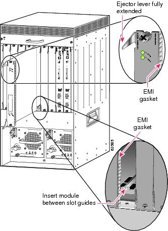
b. ![]() Carefully slide the Supervisor engine or module into the slot until the EMI gasket along the right edge of the module makes contact with the module in the slot adjacent to it and both ejector levers have closed to approximately 45 degrees with respect to the module faceplate. (See Figure 1-6.)
Carefully slide the Supervisor engine or module into the slot until the EMI gasket along the right edge of the module makes contact with the module in the slot adjacent to it and both ejector levers have closed to approximately 45 degrees with respect to the module faceplate. (See Figure 1-6.)
c. ![]() Using the thumb and forefinger of each hand, grasp the two ejector levers and exert a slight pressure to the left, moving the module approximately 0.040 inches (1 mm) to create a small gap between the module's EMI gasket and the module adjacent to it. (See Figure 1-6.)
Using the thumb and forefinger of each hand, grasp the two ejector levers and exert a slight pressure to the left, moving the module approximately 0.040 inches (1 mm) to create a small gap between the module's EMI gasket and the module adjacent to it. (See Figure 1-6.)
Figure 1-6 Clearing the EMI Gasket in a Vertical Slot Chassis

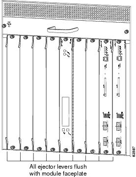
d. ![]() While pressing on the ejector levers, simultaneously close them to fully seat the Supervisor engine or module in the backplane connector. The ejector levers are fully closed when they are flush with the module faceplate. (See Figure 1-7.)
While pressing on the ejector levers, simultaneously close them to fully seat the Supervisor engine or module in the backplane connector. The ejector levers are fully closed when they are flush with the module faceplate. (See Figure 1-7.)
Figure 1-7 Ejector Lever Closure in a Vertical Slot Chassis
e. ![]() Tighten the two captive installation screws on the module.
Tighten the two captive installation screws on the module.
Note ![]() Make sure that the ejector levers are fully closed before tightening the captive installation screws.
Make sure that the ejector levers are fully closed before tightening the captive installation screws.
Note ![]() For information regarding installation details for the Cisco 7600 Internet Router, go to the following URL: http://www.cisco.com/en/US/products/hw/routers/ps368/products_module_installation_guide_book09186a008007cd9d.html
For information regarding installation details for the Cisco 7600 Internet Router, go to the following URL: http://www.cisco.com/en/US/products/hw/routers/ps368/products_module_installation_guide_book09186a008007cd9d.html
Verifying the Installation
This section describes how to verify the PSD installation.
Cisco IOS Software
To verify that the system acknowledges the new module and has brought it online, enter the show module [mod-num | all ] command.
This example shows the output of the show module command:
Router#show module
Mod Ports Card Type Model Serial No.
--- ----- -------------------------------------- ------------------ -----------
1 2 Catalyst 6000 supervisor 2 (Active) WS-X6K-SUP2-2GE SAL06396QLA
2 2 Catalyst 6000 supervisor 2 (Standby) WS-X6K-SUP2-2GE SAL061800UB
3 48 48 port 10/100 mb RJ45 WS-X6348-RJ-45 SAL06200V6W
4 3 Network Analysis Module WS-SVC-NAM-1 SAD064403UB
5 3 Persistent Storage Device WS-SVC-PSD-1 SAD060301SU
6 3 Persistent Storage Device WS-SVC-PSD-1 SAD060301SV
Mod MAC addresses Hw Fw Sw Status
--- ---------------------------------- ------ ------------ ------------ -------
1 0006.d65b.e1bc to 0006.d65b.e1bd 3.10 6.1(3) 7.5(0.94) Ok
2 0005.7485.bde8 to 0005.7485.bde9 3.7 6.1(3) 7.5(0.94) Ok
3 0009.1243.23cc to 0009.1243.23fb 6.1 5.4(2) 7.5(0.94) Ok
4 0002.7ee4.b046 to 0002.7ee4.b04d 1.0 7.2(1) 2.2(1a) Ok
5 00e0.b0ff.3630 to 00e0.b0ff.3637 0.101 7.5(0.61) 1.0(1) Ok
6 00e0.b0ff.3530 to 00e0.b0ff.3537 0.101 7.5(0.61) 1.0(1) Ok
Mod Sub-Module Model Serial Hw Status
--- --------------------------- --------------- --------------- ------- -------
1 Policy Feature Card 2 WS-F6K-PFC2 SAL06396LVK 3.3 Ok
1 Cat6k MSFC 2 daughterboard WS-F6K-MSFC2 SAL06365RJM 2.5 Ok
2 Policy Feature Card 2 WS-F6K-PFC2 SAL061735WF 3.2 Ok
2 Cat6k MSFC 2 daughterboard WS-F6K-MSFC2 SAL06131NAL 2.3 Ok
Mod Online Diag Status
--- -------------------
1 Pass
2 Pass
3 Pass
4 Pass
5 Pass
6 Pass
When the PSD initially boots, by default it runs a partial memory test. To perform a full memory test, enter the hw-module module module_number reset device:partition mem-test-full command.
A full memory test takes more time to complete than a partial memory test depending on the memory size. Table 1-5 lists the memory test time and approximate boot time for a partial memory test.
|
|
|
|---|---|
WS-SVC-PSD-1 |
9 minutes |
You also can use the hw-module module module_number mem-test-full command in a Cisco IOS system. This example shows how to do a full memory test for module 4:
Router(config)# hw-module module 4 mem-test-full
Note ![]() Cisco recommends that you run a full online diagnostic when you boot your PSD for the first time. You can use the following commands to perform this task:
Cisco recommends that you run a full online diagnostic when you boot your PSD for the first time. You can use the following commands to perform this task:
router# configure terminal diag level complete
Configuring the PSD
See the following sections for configuration tasks for the PSD. Each task in the list is identified as either required or optional.
•![]() Configuring the Supervisor for the PSD
Configuring the Supervisor for the PSD
•![]() "Adding the PSD to the Corresponding VLAN" section
"Adding the PSD to the Corresponding VLAN" section
•![]() "Initial PSD Configuration" section
"Initial PSD Configuration" section
•![]() "Transfering and Purging Data Files and Datastores" section
"Transfering and Purging Data Files and Datastores" section
•![]() "Administering the PSD" section
"Administering the PSD" section
There are several external interfaces that are available to configure and manage the PSD. They include the following:
MP (Maintenance Partition) Command Line Interface.
When you boot the MP image (from compact flash), and login to the card, you are presented with a command line interface that allows you to perform activities such as administration tasks, configuration, troubleshooting, and to upgrade the application image.
AP (Application Partition) Command Line Interface.
When you boot the AP image from the hard disk, and login to the card, you are presented with a command line interface that is similar to IOS. The AP commands allow you to configure the PSD, and to display the status of the PSD.
There is a specific subset of the PSD CLI commands for the following tasks:
•![]() Taking the PSD into service
Taking the PSD into service
•![]() Taking the PSD out of service
Taking the PSD out of service
•![]() Creating a data store for a client
Creating a data store for a client
•![]() Deleting a data store
Deleting a data store
•![]() Showing PSD related status and datastore information
Showing PSD related status and datastore information
•![]() Enabling access to a datastore
Enabling access to a datastore
•![]() Disabling access to a datastore
Disabling access to a datastore
IOS Supervisor Command Line Interface.
This is the command line provided by the IOS image on the Supervisor card. There are IOS commands that allow you to interact with the PSD card. The Supervisor CLI also provides commands by which the CSG or GGSN is configured to communicate with the PSD card.
SNMP interfaces. The SNMP agent on the PSD can be configured and activated. When activated, you can then define a read community string. A network agent with connectivity to the PSD, and knowledge of the SNMP read community string, may issue SNMP get/walk type requests to manage and monitor the PSD.
Configuring the Supervisor for the PSD
Adding the PSD to the Corresponding VLAN
By default, the PSD is in trunking mode with native VLAN 1.
Note ![]() By default the PSD will use vlan1 for its network traffic; however, you can configure the PSD to use another vlan with the persistent-store module command.
By default the PSD will use vlan1 for its network traffic; however, you can configure the PSD to use another vlan with the persistent-store module command.
Initial PSD Configuration
Before you can use the PSD for data storage, you must log into the PSD root account and configure the following:
•![]() IP address
IP address
•![]() Subnet mask
Subnet mask
•![]() IP broadcast address
IP broadcast address
•![]() IP host name
IP host name
•![]() Default gateway
Default gateway
•![]() Domain name
Domain name
•![]() Datastore Creation and Access Control
Datastore Creation and Access Control
•![]() Inservice
Inservice
•![]() If applicable, the DNS name server
If applicable, the DNS name server
•![]() If you are using an external SNMP manager to communicate with the PSD, configure the following:
If you are using an external SNMP manager to communicate with the PSD, configure the following:
–![]() SNMP MIB variables
SNMP MIB variables
–![]() Access control for the SNMP agent
Access control for the SNMP agent
–![]() System group settings on the PSD
System group settings on the PSD
To configure these required parameters for the PSD, follow these steps:
Step 1 ![]() Enter this command to verify that the PSD is installed and that the power is on:
Enter this command to verify that the PSD is installed and that the power is on:
Router# show module mod
Step 2 ![]() Establish a console session with the PSD by entering:
Establish a console session with the PSD by entering:
Router# session slot module_number processor 1
Note ![]() Sometimes attempts to session into the PSD console from the supervisor fail immediately after startup, or immediately after a PSD restart, even though the "module online" message for the PSD blade has appeared at the supervisor. Always wait 60 seconds after the "module online" message appears on the supervisor for the PSD module before you attempt to session into the PSD from the supervisor.
Sometimes attempts to session into the PSD console from the supervisor fail immediately after startup, or immediately after a PSD restart, even though the "module online" message for the PSD blade has appeared at the supervisor. Always wait 60 seconds after the "module online" message appears on the supervisor for the PSD module before you attempt to session into the PSD from the supervisor.
The hardware and firmware of the PSD performs self-checks on boot up, then notifies the supervisor that the PSD module is online. This results in the "module online" message at the supervisor console. Concurrently, the firmware starts the PSD application on the PSD processors. The PSD application requires about 50 seconds to initialize itself, and the application does not accept session requests from the supervisor until this initialization is complete.
Step 3 ![]() At the login prompt, type root to log in to the root account.
At the login prompt, type root to log in to the root account.
Step 4 ![]() At the password prompt, type cisco as the root password.
At the password prompt, type cisco as the root password.
Note ![]() If you have not changed the password from the factory-set default, a warning message displays. If you decide to change the password from the default, see the "Changing the PSD CLI Passwords" section for more information.
If you have not changed the password from the factory-set default, a warning message displays. If you decide to change the password from the default, see the "Changing the PSD CLI Passwords" section for more information.
Step 5 ![]() Configure the IP address and subnet mask by entering:
Configure the IP address and subnet mask by entering:
root@localhost# ip address ip-address subnet-mask
Step 6 ![]() Configure the IP broadcast address by entering:
Configure the IP broadcast address by entering:
root@localhost# ip broadcast broadcast-address
Step 7 ![]() Configure the IP host name used in the CLI prompt, show commands, and log messages by entering:
Configure the IP host name used in the CLI prompt, show commands, and log messages by entering:
root@localhost# ip host [host-name]
Step 8 ![]() Configure the default gateway by entering:
Configure the default gateway by entering:
root@localhost# ip gateway default-gateway
Note ![]() This gateway should always be the IP address of VLAN1 on the Supervisor.
This gateway should always be the IP address of VLAN1 on the Supervisor.
Step 9 ![]() Configure the domain name for the PSD by entering:
Configure the domain name for the PSD by entering:
root@localhost# ip domain domain-name
Step 10 ![]() Configure one or more IP addresses as DNS name servers by entering:
Configure one or more IP addresses as DNS name servers by entering:
root@localhost# ip nameserver ip-address [ip-address2] [ip-address-3]
Note ![]() The ip nameserver command can accept up to a maximum of three name server addresses (two addresses are optional).
The ip nameserver command can accept up to a maximum of three name server addresses (two addresses are optional).
Step 11 ![]() Verify the PSD configuration by entering:
Verify the PSD configuration by entering:
root@localhost# show ip
Step 12 ![]() Configure a datastore for a Cisco client by entering:
Configure a datastore for a Cisco client by entering:
root@localhost# datastore create cisco
root@localhost# datastore access enable cisco 1.2.3.4 port number
root@localhost# show datastore all or cisco
Step 13 ![]() Put the PSD inservice by entering:
Put the PSD inservice by entering:
root@localhost# in-service
Note ![]() The following steps are optional configuration tasks:
The following steps are optional configuration tasks:
Step 14 ![]() Configure the SNMP syslocation MIB variable by entering:
Configure the SNMP syslocation MIB variable by entering:
root@localhost# snmp-agent location-string
Note ![]() The MIB variables in Step 13 and Step 14 must be valid DisplayString texts, each with a maximum length of 64 characters.
The MIB variables in Step 13 and Step 14 must be valid DisplayString texts, each with a maximum length of 64 characters.
Step 15 ![]() Set the SNMP sysContact MIB variable by entering:
Set the SNMP sysContact MIB variable by entering:
root@localhost# snmp-contact contact-string
Step 16 ![]() Set the SNMP sysName MIB variable by entering:
Set the SNMP sysName MIB variable by entering:
root@localhost# snmp-name name-string
Note ![]() You can delete the SNMP location, SNMP contact, or SNMP name by entering the respective command without any parameters.
You can delete the SNMP location, SNMP contact, or SNMP name by entering the respective command without any parameters.
Step 17 ![]() Set the SNMP agent community string parameter password for read-write access by entering:
Set the SNMP agent community string parameter password for read-write access by entering:
root@localhost# snmp-community community-string
Note ![]() Clear the SNMP community string with the snmp delete community command.
Clear the SNMP community string with the snmp delete community command.
Step 18 ![]() Verify the SNMP access controls and settings by entering:
Verify the SNMP access controls and settings by entering:
root@localhost# show snmp
Step 19 ![]() Enable telnet access to your PSD module from a remote location by entering:
Enable telnet access to your PSD module from a remote location by entering:
root@localhost# telnet-server enable
After completing this configuration, the PSD is ready to use with other Cisco clients.
This example shows how to configure the PSD:
Router# session slot 8 processor 1
The default escape character is Ctrl-^, then x.
You can also type 'exit' at the remote prompt to end the session
Trying 127.0.0.81 ... Open
Cisco Persistent Storage (WS-SVC-PSD-1)
login: root
Password:
Cisco Persistent Storage Device (WS-SVC-PSD-1) Console, 1.0(1)
Copyright (C) 2002-2003 by cisco Systems, Inc.
WARNING! Default password has not been changed!
root@localhost.localdomain# ip address 192.18.12.221 255.255.255.192
root@localhost.localdomain# ip host psd1
root@psd1.localdomain# ip gateway 192.18.12.193
root@psd1.localdomain# ip domain cisco.com
root@psd1.cisco.com# ip nameserver 161.44.11.21
root@psd1.cisco.com# show ip
IP address: 192.18.12.221
Subnet mask: 255.255.255.192
IP Broadcast: 192.18.255.255
DNS Name: psd1.cisco.com
Default Gateway: 192.18.12.193
Nameserver(s): 161.44.11.21
FTP Server: disabled
Telnet Server: disabled
root@psd1.cisco.com# snmp-agent enable
root@psd1.cisco.com# snmp-agent community read
root@psd1.cisco.com# snmp-agent location "Cisco Lab, Building 10 Lab 4"
root@psd1.cisco.com# snmp contact "Lab Admin, 555-1212"
root@psd1.cisco.com# show snmp-agent
SNMP Agent: psd1.cisco.com
status: enabled
ip address: 172.18.12.221
community string: read
SNMPv1: supported
SNMPv2c: supported
SNMPv3: not-supported
sysDescr: Linux psd1.cisco.com 2.4.18 #1 SMP Wed Jul 16 11:18:19 EDT 2
003 i686
sysObjectID: OID: enterprises.ucdavis.ucdSnmpAgent.linux
sysContact: Lab Admin, 555-1212
sysName: not-configured
sysLocation: Cisco Lab, Building 10 Lab 4
root@psd1.cisco.com#
Step 1 ![]() Session into the PSD:
Session into the PSD:
router# session slot slot_num processor processor
Step 2 ![]() Issue the configuration save command.
Issue the configuration save command.
Note ![]() You can also issue the following show commands, and copy and paste the various show output into your preferred text editor:
You can also issue the following show commands, and copy and paste the various show output into your preferred text editor:
root@localhost.localdomain# show ip
root@localhost.localdomain# show snmp-agent
root@localhost.localdomain# show datastore all .
Save this file in a secure location for backup purposes.
Note ![]() For specific information on how to configure the PSD to communicate with the CSG, refer to the "PSD Configuration for Content Services Gateway" chapter in the Cisco Content Service Gateway Installation and Configuration Guide.
For specific information on how to configure the PSD to communicate with the CSG, refer to the "PSD Configuration for Content Services Gateway" chapter in the Cisco Content Service Gateway Installation and Configuration Guide.
Transfering and Purging Data Files and Datastores
The PSD allows you transfer and purge whole datastores, as well as individual files that exist in a datastore. See Troubleshooting the PSD for more information about how to identify corrupt data files.
To transfer and purge datastores and datastore files, perform the following procedure:
Step 1 ![]() Issue the datatstore transfer command to push files to a designated URL using FTP. You can keep or delete all data files, all salvage files, or all files. Here is the syntax:
Issue the datatstore transfer command to push files to a designated URL using FTP. You can keep or delete all data files, all salvage files, or all files. Here is the syntax:
	datastore transfer {keep | delete} {data-files | salvage-files | all} data-store-name
    ftp-url
The specified URL has the following format: ftp://username:password@hostname/fully-qualified-destination-directory
Step 2 ![]() After you have transferred data and/or salvage files to an FTP server, you can purge specific files of a datastore by issuing the datastore purge command. You can purge data files, salvage files, or all files. Here is the syntax:
After you have transferred data and/or salvage files to an FTP server, you can purge specific files of a datastore by issuing the datastore purge command. You can purge data files, salvage files, or all files. Here is the syntax:
datastore purge transferred {data-files | salvage-files | all} data-store-name
Administering the PSD
This section contains the various administrative tasks you can perform on the PSD with Cisco IOS:
•![]() Changing the PSD CLI Passwords
Changing the PSD CLI Passwords
Logging in to the PSD
Note ![]() The PSD has one user level "root". The default password is "cisco".
The PSD has one user level "root". The default password is "cisco".
Table 1-6 shows the user levels and passwords for the PSD's Application Partition.
|
|
|
|---|---|
User |
Password |
root |
cisco |
Table 1-7 shows the user levels and passwords for the PSD's Application Partition.
|
|
|
|---|---|
User |
Password |
root |
cisco |
guest |
cisco |
Note ![]() The guest account in the PSD maintenance image has "All Read" and "All Write" privileges. On the application image, the root user has full access and there is no "guest" account.
The guest account in the PSD maintenance image has "All Read" and "All Write" privileges. On the application image, the root user has full access and there is no "guest" account.
When you boot into either the application image or the maintenance image and set up IP information, that information is synched between the images. However, if you change passwords, that information is not synched between the images, and is not reflected on the unchanged image.
To allow remote Telnet sessions, use the telnet-server enable command.
To log in to the PSD, follow these steps:
Step 1 ![]() Log in to the Catalyst 6500 switch using the Telnet connection or the console port connection.
Log in to the Catalyst 6500 switch using the Telnet connection or the console port connection.
Step 2 ![]() At the CLI prompt, establish a console session with the PSD using the session slot slot_number processor 1 command, as follows:
At the CLI prompt, establish a console session with the PSD using the session slot slot_number processor 1 command, as follows:
Router# session slot 8 processor 1
The default escape character is Ctrl-^, then x.
You can also type 'exit' at the remote prompt to end the session
Trying 127.0.0.81 ... Open
Persistent Storage Module (WS-SVC-PSD-1)
Step 3 ![]() At the PSD login prompt, type root to log in as the root user or guest to log in as a guest user.
At the PSD login prompt, type root to log in as the root user or guest to log in as a guest user.
login: root
Step 4 ![]() At the password prompt, enter the password for the account. The default password for the root account is "cisco" and the default password for the guest account is "cisco".
At the password prompt, enter the password for the account. The default password for the root account is "cisco" and the default password for the guest account is "cisco".
Password:
After a successful login, the command line prompt appears as follows:
Persistent Storage Module (WS-SVC-PSD-1) Console, 1.0(1)
Copyright (c) 1999-2002 by cisco Systems, Inc.
WARNING! Default password has not been changed!
root@localhost#
Changing the PSD CLI Passwords
If you have not changed the password from the factory-set default, a warning message displays when you log in to the PSD.
Note ![]() New passwords must be at least six characters in length, and may include uppercase and lowercase letters, numbers, and punctuation marks.
New passwords must be at least six characters in length, and may include uppercase and lowercase letters, numbers, and punctuation marks.
Note ![]() If the PSD maintenance image passwords are lost for the root or guest account, the maintenance image must be upgraded. After the upgrade, the passwords are set to the default. See Table 1-6.
If the PSD maintenance image passwords are lost for the root or guest account, the maintenance image must be upgraded. After the upgrade, the passwords are set to the default. See Table 1-6.
To change the password, follow these steps while you are logged in to the root account on the PSD:
Step 1 ![]() Enter this command:
Enter this command:
root@localhost# password username
To change the root password, make a Telnet connection to the PSD and use the password root command.
To change the guest password in MP mode only, make a Telnet connection to the PSD and use the password guest command.
Step 2 ![]() Enter the new password:
Enter the new password:
Changing password for user root
New UNIX password:
Step 3 ![]() Enter the new password again:
Enter the new password again:
Retype new UNIX password:
passwd: all authentication tokens updated successfully
This example shows how to set the password for the root account:
root@localhost# password root
Changing password for user root
New UNIX password:
Retype new UNIX password:
passwd: all authentication tokens updated successfully
If you forget or lose the password, you can enter the clear module pc-module module number password command from the IOS Supervisor CLI to restore the password for the root account to "cisco".
Resetting the PSD
If you cannot reach the PSD through the CLI or an external Telnet session, enter the hardware_module module module_number reset command to reset and reboot the PSD. The reset process requires several minutes.
When the PSD initially boots, by default it runs a partial memory test. To perform a full memory test, use the mem-test-full keyword in the hw-module module module_number reset device:partition mem-test-full command.
When you next reset the PSD, the full memory test runs. A full memory test takes more time to complete than a partial memory test. See Table 1-5 for memory test times.
You can also use the hw-module module module_number mem-test-full configuration to run a memory test. This example shows a full memory test for module 5:
Router(config)# hw-module slot 5 memory test full
To reset the module from the CLI, perform this task in privileged mode:
This example shows how to reset the PSD that is installed in slot 9 from the CLI:
Router# hardware_module mod 9 reset cf:1 memtest-full
Proceed with reload of module? [confirm] y
% reset issued for module 9
Note ![]() For the boot device, you can specify hdd:1 for the application image or cf:1 for the maintenance image.
For the boot device, you can specify hdd:1 for the application image or cf:1 for the maintenance image.
Upgrading the PSD Software
You can upgrade both the application software and the maintenance software. To upgrade the application software, see the "Upgrading the PSD Application Software" section. To upgrade the maintenance software, see the "Upgrading the PSD Maintenance Software" section.
Note ![]() Upgrading from Release 1.x to 2.0 will preserve data when you upgrade without the "-install" option.
Upgrading from Release 1.x to 2.0 will preserve data when you upgrade without the "-install" option.
Upgrading the PSD Maintenance Software
Note ![]() In the event that you need to upgrade your MP image, refer to the following URL for image location: http://www.cisco.com/cgi-bin/tablebuild.pl/cat6000-serv-maint
In the event that you need to upgrade your MP image, refer to the following URL for image location: http://www.cisco.com/cgi-bin/tablebuild.pl/cat6000-serv-maint
To upgrade the PSD maintenance software, follow these steps:
Step 1 ![]() Copy the PSD maintenance software image to a directory accessible to FTP.
Copy the PSD maintenance software image to a directory accessible to FTP.
Step 2 ![]() Log in to the switch through the console port or through a Telnet session.
Log in to the switch through the console port or through a Telnet session.
Step 3 ![]() If the PSD is running in the application image go to Step 4. If the PSD is not running in the application image, enter this command in the privileged mode:
If the PSD is running in the application image go to Step 4. If the PSD is not running in the application image, enter this command in the privileged mode:
Router# hardware_module module 9 reset
Device BOOT variable for reset = hdd:1
Warning:Device list is not verified.
Proceed with reload of module? [confirm]
% reset issued for module 9
Router#
00:31:11:%SNMP-5-MODULETRAP:Module 9 [Down] Trap
00:31:11:SP:The PC in slot 9 is shutting down. Please wait ...
00:31:25:SP:PC shutdown completed for module 9
00:31:25:%C6KPWR-SP-4-DISABLED:power to module in slot 9 set off (admin
request)
00:31:28:SP:Resetting module 9 ...
00:31:28:%C6KPWR-SP-4-ENABLED:power to module in slot 9 set on
00:33:26:%SNMP-5-MODULETRAP:Module 9 [Up] Trap
00:33:26:%DIAG-SP-6-BYPASS:Module 9:Online Diagnostics is Bypassed
00:33:26:%OIR-SP-6-INSCARD:Card inserted in slot 9, interfaces are now
online
Step 4 ![]() After the PSD is back online, establish a console session with the PSD and log in to the root account.
After the PSD is back online, establish a console session with the PSD and log in to the root account.
Step 5 ![]() Upgrade the PSD maintenance software by entering:
Upgrade the PSD maintenance software by entering:
root@localhost# upgrade ftp-url
ftp-url is the FTP location and name of the PSD software image file.
Note ![]() If the FTP server does not allow anonymous users, use the following syntax for the ftp-url value: ftp://user@host/absolute-path/filename. Enter your password when prompted.
If the FTP server does not allow anonymous users, use the following syntax for the ftp-url value: ftp://user@host/absolute-path/filename. Enter your password when prompted.
Step 6 ![]() Follow the screen prompts during the upgrade.
Follow the screen prompts during the upgrade.
Step 7 ![]() After completing the upgrade, log out of the PSD.
After completing the upgrade, log out of the PSD.
Step 8 ![]() Boot into the maintenance image with the following command to reset the PSD maintenance software:
Boot into the maintenance image with the following command to reset the PSD maintenance software:
Router# hardware_module module 9 reset cf:1
Device BOOT variable for reset = cf:1
Warning:Device list is not verified.
Proceed with reload of module? [confirm]
% reset issued for module 9
Router#
00:16:06:%SNMP-5-MODULETRAP:Module 9 [Down] Trap
00:16:06:SP:The PC in slot 9 is shutting down. Please wait ...
00:16:21:SP:PC shutdown completed for module 9
00:16:21:%C6KPWR-SP-4-DISABLED:power to module in slot 9 set off (admin
request)
00:16:24:SP:Resetting module 9 ...
00:16:24:%C6KPWR-SP-4-ENABLED:power to module in slot 9 set on
00:18:21:%SNMP-5-MODULETRAP:Module 9 [Up] Trap
00:18:21:%DIAG-SP-6-BYPASS:Module 9:Online Diagnostics is Bypassed
00:18:21:%OIR-SP-6-INSCARD:Card inserted in slot 9, interfaces are now
online
Router#
Step 9 ![]() (Optional) Verify the initial configuration after the PSD comes back online by logging into the PSD root account and enter the following command:
(Optional) Verify the initial configuration after the PSD comes back online by logging into the PSD root account and enter the following command:
root@localhost# show ip
Step 10 ![]() Upgrade the Bios using the following commands:
Upgrade the Bios using the following commands:
a. ![]() Boot the PSD to the MP.
Boot the PSD to the MP.
b. ![]() At the login prompt enter guest.
At the login prompt enter guest.
c. ![]() At the password prompt enter cisco.
At the password prompt enter cisco.
d. ![]() Enter router# hw-module module module_number cf:1
Enter router# hw-module module module_number cf:1
e. ![]() Session to the PSD from the switch CLI.
Session to the PSD from the switch CLI.
f. ![]() Issue the session slot module_number proc 1 command.
Issue the session slot module_number proc 1 command.
g. ![]() Enter upgrade-bios and follow the prompts
Enter upgrade-bios and follow the prompts
h. ![]() Enter the following Bios file name: B01MQ009.ROM
Enter the following Bios file name: B01MQ009.ROM
Step 11 ![]() (Optional) Reboot into the application image by entering:
(Optional) Reboot into the application image by entering:
Router# hardware_module module 9 reset
This example shows how to upgrade the PSD maintenance software:
Router#
Router# hardware_module module 9 reset
Device BOOT variable for reset = hdd:1
Warning:Device list is not verified.
Proceed with reload of module? [confirm]
% reset issued for module 9
Router#
00:31:11:%SNMP-5-MODULETRAP:Module 9 [Down] Trap
00:31:11:SP:The PC in slot 9 is shutting down. Please wait ...
00:31:25:SP:PC shutdown completed for module 9
00:31:25:%C6KPWR-SP-4-DISABLED:power to module in slot 9 set off (admin
request)
00:31:28:SP:Resetting module 9 ...
00:31:28:%C6KPWR-SP-4-ENABLED:power to module in slot 9 set on
00:33:26:%SNMP-5-MODULETRAP:Module 9 [Up] Trap
00:33:26:%DIAG-SP-6-BYPASS:Module 9:Online Diagnostics is Bypassed
00:33:26:%OIR-SP-6-INSCARD:Card inserted in slot 9, interfaces are now
online
Router#
Router# session slot 9 proc 1
The default escape character is Ctrl-^, then x.
You can also type 'exit' at the remote prompt to end the session
Trying 127.0.0.91 ... Open
Persistent Storage Module (WS-SVC-PSD-1)
login:root
Password:
Cisco Persistent Storage Module (WS-SVC-PSD-1) Console, 2.2(0.1)
Copyright (c) 1999-2002 by cisco Systems, Inc.
WARNING! Default password has not been changed!
root@localhost.cisco.com#
root@localhost.cisco.com# upgrade ftp://host/pub/rmon/mp.1-1-0-1.bin.gz
user password:
Downloading image...
ftp://host/pub/rmon/mp.1-1-0-1.bin.gz (11065K)
- [########################] 11065K | 837.65K/s
11331153 bytes transferred in 13.21 sec (837.64k/sec)
Uncompressing the image...
Verifying the image...
Applying the Maintenance image.
This may take several minutes...
Upgrade of Maintenance image completed successfully.
root@hostname.cisco.com# exit
Router# hardware_module module 9 reset cf:1
Device BOOT variable for reset = cf:1
Warning:Device list is not verified.
Proceed with reload of module? [confirm]
% reset issued for module 9
Router#
02:27:19:%SNMP-5-MODULETRAP:Module 9 [Down] Trap
02:27:19:SP:The PC in slot 9 is shutting down. Please wait ...
02:27:36:SP:PC shutdown completed for module 9
02:27:36:%C6KPWR-SP-4-DISABLED:power to module in slot 9 set off (admin
request)
02:27:39:SP:Resetting module 9 ...
02:27:39:%C6KPWR-SP-4-ENABLED:power to module in slot 9 set on
02:29:37:%SNMP-5-MODULETRAP:Module 9 [Up] Trap
02:29:37:%DIAG-SP-6-BYPASS:Module 9:Online Diagnostics is Bypassed
02:29:37:%OIR-SP-6-INSCARD:Card inserted in slot 9, interfaces are now
online
Router#
Upgrading the PSD Application Software
To upgrade the PSD application software, follow these steps:
Step 1 ![]() Copy the PSD application software image to a directory accessible to FTP.
Copy the PSD application software image to a directory accessible to FTP.
Step 2 ![]() Log in to the switch through the console port or through a Telnet session.
Log in to the switch through the console port or through a Telnet session.
Step 3 ![]() If the PSD is running in the maintenance image, go to Step 4. If the PSD is not running in the maintenance image, enter this command in privileged mode:
If the PSD is running in the maintenance image, go to Step 4. If the PSD is not running in the maintenance image, enter this command in privileged mode:
Router# hardware_module module 9 reset cf:1
Device BOOT variable for reset = cf:1
Warning:Device list is not verified.
Proceed with reload of module? [confirm]
% reset issued for module 9
Router#
00:03:31:%SNMP-5-MODULETRAP:Module 9 [Down] Trap
00:03:31:SP:The PC in slot 9 is shutting down. Please wait ...
00:03:41:%SNMP-5-COLDSTART:SNMP agent on host R1 is undergoing a cold
start
00:03:46:SP:PC shutdown completed for module 9
00:03:46:%C6KPWR-SP-4-DISABLED:power to module in slot 9 set off (admin
request)
00:03:49:SP:Resetting module 9 ...
00:03:49:%C6KPWR-SP-4-ENABLED:power to module in slot 9 set on
00:05:53:%SNMP-5-MODULETRAP:Module 9 [Up] Trap
00:05:53:%DIAG-SP-6-BYPASS:Module 9:Online Diagnostics is Bypassed
00:05:53:%OIR-SP-6-INSCARD:Card inserted in slot 9, interfaces are now
online
Router#
Step 4 ![]() After the PSD is back online, establish a console session with the PSD and log in to the root account.
After the PSD is back online, establish a console session with the PSD and log in to the root account.
Router# session slot 9 proc 1
The default escape character is Ctrl-^, then x.
You can also type 'exit' at the remote prompt to end the session
Trying 127.0.0.91 ... Open
Persistent Storage Module (WS-SVC-PSD-1)
Maintenance Partition
login:root
Password:
Persistent Storage Module (WS-SVC-PSD-1) Console, 1.4(1)m
Copyright (c) 1999, 2000, 2001 by cisco Systems, Inc.
Step 5 ![]() Upgrade the PSD application software by entering:
Upgrade the PSD application software by entering:
root@localhost# upgrade ftp-url
ftp-url is the FTP location and name of the PSD software image file.
Note ![]() If the FTP server does not allow anonymous users, use the following syntax for the ftp-url value: ftp://user@host/absolute-path/filename. Enter your password when prompted.
If the FTP server does not allow anonymous users, use the following syntax for the ftp-url value: ftp://user@host/absolute-path/filename. Enter your password when prompted.
Step 6 ![]() Follow the screen prompts during the upgrade.
Follow the screen prompts during the upgrade.
Step 7 ![]() After completing the upgrade, log out of the PSD.
After completing the upgrade, log out of the PSD.
Step 8 ![]() Reset the PSD to the AP image by entering:
Reset the PSD to the AP image by entering:
Router# hardware_module mod 8 reset
Device BOOT variable for reset =
Warning:Device list is not verified.
Proceed with reload of module? [confirm]
% reset issued for module 8
Router#
00:26:55:%SNMP-5-MODULETRAP:Module 8 [Down] Trap
00:26:55:SP:The PC in slot 8 is shutting down. Please wait ...
Step 9 ![]() (Optional) Verify the initial configuration after the PSD comes back online by logging into the PSD root account and then entering:
(Optional) Verify the initial configuration after the PSD comes back online by logging into the PSD root account and then entering:
root@localhost# show ip
root@localhost# show snmp
This example shows how to upgrade the PSD application software:
Router# hardware_module module 9 reset cf:1
Device BOOT variable for reset = cf:1
Warning:Device list is not verified.
Proceed with reload of module? [confirm]
% reset issued for module 9
Router#
00:16:06:%SNMP-5-MODULETRAP:Module 9 [Down] Trap
00:16:06:SP:The PC in slot 9 is shutting down. Please wait ...
00:16:21:SP:PC shutdown completed for module 9
00:16:21:%C6KPWR-SP-4-DISABLED:power to module in slot 9 set off (admin
request)
00:16:24:SP:Resetting module 9 ...
00:16:24:%C6KPWR-SP-4-ENABLED:power to module in slot 9 set on
00:18:21:%SNMP-5-MODULETRAP:Module 9 [Up] Trap
00:18:21:%DIAG-SP-6-BYPASS:Module 9:Online Diagnostics is Bypassed
00:18:21:%OIR-SP-6-INSCARD:Card inserted in slot 9, interfaces are now
online
Router# session slot 9 proc 1
The default escape character is Ctrl-^, then x.
You can also type 'exit' at the remote prompt to end the session
Trying 127.0.0.91 ... Open
Persistent Storage Module (WS-SVC-PSD-1)
Maintenance image
login:root
Password:
Maintenance image version:1.4(1)m
root@localhost.cisco.com# upgrade ftp://psdlab-pc1/pub/rmon/c6psd2.2-2-0-8.bin.gz
Downloading the image. This may take several minutes...
ftp://psdlab-pc1/pub/rmon/c6psd2.2-2-0-8.bin.gz (59198K)
/tmp/upgrade.gz [########################] 59198K | 821.24K/s
60619473 bytes transferred in 72.08 sec (821.23k/sec)
Upgrade file ftp://psdlab-pc1/pub/rmon/c6psd2.2-2-0-8.bin.gz is downloaded.
Upgrading will wipe out the contents on the hard disk.
Do you want to proceed installing it [y|N]:y
Proceeding with upgrade. Please do not interrupt.
If the upgrade is interrupted or fails, boot into
Maintenance image again and restart upgrade.
Creating PSD application image file...
Initializing the application image partition...
Applying the image, this may take several minutes...
Performing post install, please wait...
Upgrade complete. You can boot from the Application image.
root@hostname.cisco.com# exit
[Connection to 127.0.0.91 closed by foreign host]
Router#
Router# hardware_module module 9 reset
Device BOOT variable for reset =
Warning:Device list is not verified.
Proceed with reload of module? [confirm] y
% reset issued for module 9
Router#
00:24:04:%SNMP-5-MODULETRAP:Module 9 [Down] Trap
00:24:04:SP:The PC in slot 9 is shutting down. Please wait ...
00:24:18:SP:PC shutdown completed for module 9
00:24:18:%C6KPWR-SP-4-DISABLED:power to module in slot 9 set off (admin
request)
00:24:21:SP:Resetting module 9 ...
00:24:21:%C6KPWR-SP-4-ENABLED:power to module in slot 9 set on
00:26:19:%SNMP-5-MODULETRAP:Module 9 [Up] Trap
00:26:19:%DIAG-SP-6-BYPASS:Module 9:Online Diagnostics is Bypassed
00:26:19:%OIR-SP-6-INSCARD:Card inserted in slot 9, interfaces are now
online
Saving and Restoring Configurations
For general information about saving and restoring configurations, refer to the Catalyst 6000 Family IOS Software Configuration Guide or to the Cisco 7600 Series Internet Router IOS Software Configuration Guide.
The PSD provides a method to save and restore your configuration.
Additionally, if you need to change PSD modules in the Catalyst chassis, you will need to configure the new module. Cisco recommends that you perform the following procedure to save and store your PSD configuration details:
Step 1 ![]() Session into the PSD:
Session into the PSD:
router# session slot slot_num processor processor
Issue the root@localhost.localdomain# show ip command and archive the IP address information for future reference.
Step 2 ![]() Establish connectivity to an IP server on which to write files.
Establish connectivity to an IP server on which to write files.
Step 3 ![]() Issue the configuration save command.
Issue the configuration save command.
Note ![]() Using certain special characters in a password can cause problems when you issue the configuration save command. The characters are as follows: ` & ( ) | ; " ' < >
Using certain special characters in a password can cause problems when you issue the configuration save command. The characters are as follows: ` & ( ) | ; " ' < >
If you choose not to put an FTP server on your network, you can use the following instructions to save and restore your configuration.
Step 1 ![]() Session into the PSD:
Session into the PSD:
router# session slot slot_num processor processor
Step 2 ![]() From there, issue the following show commands, and copy and paste the various show output into your preferred text editor:
From there, issue the following show commands, and copy and paste the various show output into your preferred text editor:
root@localhost.localdomain# show ip
root@localhost.localdomain# show snmp-agent
root@localhost.localdomain# show datastore all
Step 3 ![]() Save this file in a secure location for backup purposes.
Save this file in a secure location for backup purposes.
Restoring
If you need to restore a previous configuration, use the following instructions:
Step 1 ![]() Session into the PSD:
Session into the PSD:
router# session slot slot_num processor processor
Step 2 ![]() Enter the restore command. The PSD will reboot 2 or 3 times, will copy the new configuration at boot up and restore the configuration
Enter the restore command. The PSD will reboot 2 or 3 times, will copy the new configuration at boot up and restore the configuration
Step 3 ![]() Boot the PSD again, and it reads the command.
Boot the PSD again, and it reads the command.
Note ![]() Issuing the configuration clear command clears the configuration, and causes the PSD to go offline. The PSD is still running and ready to be configured with new values. Use this command sparingly.
Issuing the configuration clear command clears the configuration, and causes the PSD to go offline. The PSD is still running and ready to be configured with new values. Use this command sparingly.
Note ![]() If you restore a configuration that is identical to the existing configuration, the new configuration will overwrite the existing configuration, and the PSD will go through the normal reboot sequence it would use if the configuration had been different.
If you restore a configuration that is identical to the existing configuration, the new configuration will overwrite the existing configuration, and the PSD will go through the normal reboot sequence it would use if the configuration had been different.
Other Configuration Tasks
Configuring the Boot Partitions on the PC Image
The PC compact flash is divided into 2 distinct operating systems. There is a Maintenance Partition (MP) that is common to all similar Cisco service cards, and there is an Application Partition (AP) that stores the PSD image. To configure the the MP and AP for the PSD, perform the following commands in global configuration mode:
Note ![]() Upon intial power-on the PSD card boots to the application image.
Upon intial power-on the PSD card boots to the application image.
Enter the following router configuration command, where x is the slot number for the PSD:
Router(config)# boot device module x hdd:1
Note ![]() We advise that you only use this procedure when directed by Cisco TAC.
We advise that you only use this procedure when directed by Cisco TAC.
Additional PSD Software Commands
The PSD also supports these CLI commands, which are described in more detail in the Catalyst 6000 Family IOS Command Reference publication. These commands are grouped according to mode. These sections describe the Cisco IOS commands that interact with the PSD:
•![]() User and Privileged EXEC Commands
User and Privileged EXEC Commands
•![]() The "Command Reference" section lists the PSD Application Commands
The "Command Reference" section lists the PSD Application Commands
User and Privileged EXEC Commands
The following commands are all performed in User and Privileged EXEC mode:
Configuration Commands
The following commands are all performed in either global configuration mode or the interface configuration mode:
Global Configuration Mode
The following commands are all performed in global configuration mode:
Interface Configuration Mode
The following commands are configuration commands performed in interface configuration mode:
MP Commands
Administrators can boot the MP and session into the CLI. There is a set of interfaces available on the MP to administer and diagnose the PSD. One of the key features of the MP is to provide the ability to install a new AP image. The following table summarizes the MP commands:
Troubleshooting the PSD
This section provides troubleshooting information for the PSD.
Symptom When a reset command is entered from the Supervisor CLI, the system always boots into the maintenance image.
Possible Cause If the boot device is configured in the Supervisor as cf:1, typing a reset module command always boots to the maintenance image.
Recommended Action Override the configured boot device in the Supervisor by entering the boot string during reset.
•![]() In Cisco IOS software, reconfigure using the no boot device cf:1 command.
In Cisco IOS software, reconfigure using the no boot device cf:1 command.
Symptom You are unable to log into the maintenance image with the same password for the PSD application image.
Possible Cause The PSD application image and the maintenance image have different password databases for the root and guest accounts. The default passwords for root and guest differ between the maintenance image and the PSD application image. Any password change performed in the PSD application image does not change the maintenance image password, and vice versa.
Recommended Action Use the maintenance image password.
Symptom You lost your password for the maintenance image and want to recover it.
Possible Cause The maintenance image does not support resetting passwords from the switch. Upgrading the maintenance image sets the password for root and guest to default in the maintenance image.
Recommended Action Use the default maintenance image passwords. Refer to Table 1-6.
Symptom When the PSD initially boots, by default it runs a partial memory test and you want to run a complete memory test.
Possible Cause The partial memory test is the default configuration.
Recommended Action To perform a full memory test, enter the hw-module module module_number reset device:partition mem-test-full command.
Note ![]() A full memory test takes significantly more time to complete.
A full memory test takes significantly more time to complete.
You can also use the hw-module module module_number memory test full command. For example:
Router# config term
Router(config)# hw-module module 5 memory test full
Warning:Device list is not verified but still set in the boot string.
Console> (enable) show boot device module 5
Device BOOT variable = cf:1
Memory-test set to FULL
This example shows how to reset the partial memory test:
Console> (enable) set boot device cf:1 5
Device BOOT variable = cf:1
Memory-test set to PARTIAL
Warning:Device list is not verified but still set in the boot string.
Console> (enable)
Console> (enable) show boot device module 4
Device BOOT variable = cf:1
Memory-test set to PARTIAL
Symptom You cannot connect to the PSD.
Possible Cause The initial configuration is incorrect or not configured.
Recommended Action Reconfigure the PSD as described in the "Configuring the PSD" section.
Symptom The PSD fails to upgrade.
Possible Cause The URL to the server or the image name is incorrect.
Recommended Action Make sure the URL you specified is valid. Make sure the image name you specified in the URL is an official Cisco image name.
Symptom The PSD fails to reconfigure.
Possible Cause The PSD might have experienced a hardware failure.
Recommended Action Refer to the configuration settings that you previously saved.
Symptom You have a corrupt data file, need to check for corrupt data files, or need to identify unread files.
Possible Cause The PSD reloaded, or was improperly shut down.
Recommended Action To check for previously read files that are corrupt, FTP to the PSD and check the "Salvage" directory. Additionally, to identify if any unread files are corrupt, issue the datastore validate command.
Note ![]() If a datastore is full, issuing this command can take in excess of 30 minutes to complete.
If a datastore is full, issuing this command can take in excess of 30 minutes to complete.
Note ![]() You can retrieve data at any time, but you should not destroy a database until the client has read all data.
You can retrieve data at any time, but you should not destroy a database until the client has read all data.
Standards Compliance Specifications
Refer to Appendix A, "Specifications," in the Catalyst 6000 Family Installation Guide and the Catalyst 6000 Regulatory Compliance and Safety Information publication for the standards compliance specifications.
FCC Class B Compliance
This equipment has complies with the limits for a Class B digital device in accordance with the specifications in part 15 of the FCC rules.
The following information is for FCC compliance of Class B devices: The equipment described in this manual generates and may radiate radio-frequency energy. If it is not installed in accordance with Cisco's installation instructions, it may cause interference with radio and television reception. This equipment has been tested and found to comply with the limits for a Class B digital device in accordance with the specifications in part 15 of the FCC rules. These specifications are designed to provide reasonable protection against such interference in a residential installation. There is no guarantee that interference will not occur in a particular installation.
Modifying the equipment without Cisco's written authorization may result in the equipment no longer complying with FCC requirements for Class A or Class B digital devices. In that event, your right to use the equipment may be limited by FCC regulations, and you may be required to correct any interference to radio or television communications at your own expense.
Note ![]() Modifications to this device not specifically approved by Cisco Systems could void the user's authority to continue operating the device.
Modifications to this device not specifically approved by Cisco Systems could void the user's authority to continue operating the device.
Refer to the Catalyst 6000 Family Installation Guide and the Catalyst 6000 Regulatory Compliance and Safety Information publication for additional FCC class compliance information.
Copyright Notices
Third-party software used under license accompanies the Cisco Persistent Storage Module Software, release 1.1(1). One or more of the following notices may apply in connection with the license and use of such third-party software.
GNU General Public License
The Persistent Storage Device contains software covered under the GNU Public License. If you would like to obtain the source for the modified GPL code in the Persistent Storage Device, please send a request to psd-sw-req@Cisco.com.
GNU General Public License
License Text
Copyright (C) 1989, 1991 Free Software Foundation, Inc.
59 Temple Place - Suite 330, Boston, MA 02111-1307, USA
Everyone is permitted to copy and distribute verbatim copies of this license document, but changing it is not allowed.
Preamble
The licenses for most software are designed to take away your freedom to share and change it. By contrast, the GNU General Public License is intended to guarantee your freedom to share and change free software—to make sure the software is free for all its users. This General Public License applies to most of the Free Software Foundation's software and to any other program whose authors commit to using it. (Some other Free Software Foundation software is covered by the GNU Library General Public License instead.) You can apply it to your programs, too.
When we speak of free software, we are referring to freedom, not price. Our General Public Licenses are designed to make sure that you have the freedom to distribute copies of free software (and charge for this service if you wish), that you receive source code or can get it if you want it, that you can change the software or use pieces of it in new free programs; and that you know you can do these things.
To protect your rights, we need to make restrictions that forbid anyone to deny you these rights or to ask you to surrender the rights. These restrictions translate to certain responsibilities for you if you distribute copies of the software, or if you modify it.
For example, if you distribute copies of such a program, whether gratis or for a fee, you must give the recipients all the rights that you have. You must make sure that they, too, receive or can get the source code. And you must show them these terms so they know their rights.
We protect your rights with two steps: (1) copyright the software, and (2) offer you this license which gives you legal permission to copy, distribute and/or modify the software. Also, for each author's protection and ours, we want to make certain that everyone understands that there is no warranty for this free software. If the software is modified by someone else and passed on, we want its recipients to know that what they have is not the original, so that any problems introduced by others will not reflect on the original authors' reputations.
Finally, any free program is threatened constantly by software patents. We wish to avoid the danger that redistributors of a free program will individually obtain patent licenses, in effect making the program proprietary. To prevent this, we have made it clear that any patent must be licensed for everyone's free use or not licensed at all.
The precise terms and conditions for copying, distribution and modification follow.
TERMS AND CONDITIONS FOR COPYING, DISTRIBUTION AND MODIFICATION
0. This License applies to any program or other work which contains a notice placed by the copyright holder saying it may be distributed under the terms of this General Public License. The "Program," below, refers to any such program or work, and a "work based on the Program" means either the Program or any derivative work under copyright law: that is to say, a work containing the Program or a portion of it, either verbatim or with modifications and/or translated into another language. (Hereinafter, translation is included without limitation in the term "modification".) Each licensee is addressed as "you."
Activities other than copying, distribution and modification are not covered by this License; they are outside its scope. The act of running the Program is not restricted, and the output from the Program is covered only if its contents constitute a work based on the Program (independent of having been made by running the Program). Whether that is true depends on what the Program does.
1. You may copy and distribute verbatim copies of the Program's source code as you receive it, in any medium, provided that you conspicuously and appropriately publish on each copy an appropriate copyright notice and disclaimer of warranty; keep intact all the notices that refer to this License and to the absence of any warranty; and give any other recipients of the Program a copy of this License along with the Program.
You may charge a fee for the physical act of transferring a copy, and you may at your option offer warranty protection in exchange for a fee.
2. You may modify your copy or copies of the Program or any portion of it, thus forming a work based on the Program, and copy and distribute such modifications or work under the terms of Section 1 above, provided that you also meet all of these conditions:
a) You must cause the modified files to carry prominent notices stating that you changed the files and the date of any change.
b) You must cause any work that you distribute or publish, that in whole or in part contains or is derived from the Program or any part thereof, to be licensed as a whole at no charge to all third parties under the terms of this License.
c) If the modified program normally reads commands interactively when run, you must cause it, when started running for such interactive use in the most ordinary way, to print or display an announcement including an appropriate copyright notice and a notice that there is no warranty (or else, saying that you provide a warranty) and that users may redistribute the program under these conditions, and telling the user how to view a copy of this License. (Exception: if the Program itself is interactive but does not normally print such an announcement, your work based on the Program is not required to print an announcement.)
These requirements apply to the modified work as a whole. If identifiable sections of that work are not derived from the Program, and can be reasonably considered independent and separate works in themselves, then this License, and its terms, do not apply to those sections when you distribute them as separate works. But when you distribute the same sections as part of a whole which is a work based on the Program, the distribution of the whole must be on the terms of this License, whose permissions for other licensees extend to the entire whole, and thus to each and every part regardless of who wrote it.
Thus, it is not the intent of this section to claim rights or contest your rights to work written entirely by you; rather, the intent is to exercise the right to control the distribution of derivative or collective works based on the Program.
In addition, mere aggregation of another work not based on the Program with the Program (or with a work based on the Program) on a volume of a storage or distribution medium does not bring the other work under the scope of this License.
3. You may copy and distribute the Program (or a work based on it, under Section 2) in object code or executable form under the terms of Sections 1 and 2 aboveprovided that you also do one of the following:
a) Accompany it with the complete corresponding machine-readable source code, which must be distributed under the terms of Sections 1 and 2 above on a mediumcustomarily used for software interchange; or,
b) Accompany it with a written offer, valid for at least three years, to give any third party, for a charge no more than your cost of physically performing sourcedistribution, a complete machine-readable copy of the corresponding source code, to be distributed under the terms of Sections 1 and 2 above on a medium customarily used for software interchange; or,
c) Accompany it with the information you received as to the offer to distribute corresponding source code. (This alternative is allowed only for noncommercial distribution and only if you received the program in object code or executable form with such an offer, in accord with Subsection b above.)
The source code for a work means the preferred form of the work for making modifications to it. For an executable work, complete source code means all the source code for all modules it contains, plus any associated interface definition files, plus the scripts used to control compilation and installation of the executable.
However, as a special exception, the source code distributed need not include anything that is normally distributed (in either source or binary form) with the major components (compiler, kernel, and so on) of the operating system on which the executable runs, unless that component itself accompanies the executable.
If distribution of executable or object code is made by offering access to copy from a designated place, then offering equivalent access to copy the source code from the same place counts as distribution of the source code, even though third parties are not compelled to copy the source along with the object code.
4. You may not copy, modify, sublicense, or distribute the Program except as expressly provided under this License. Any attempt otherwise to copy, modify, sublicense or distribute the Program is void, and will automatically terminate your rights under this License. However, parties who have received copies, or rights, from you under this License will not have their licenses terminated so long as such parties remain in full compliance.
5. You are not required to accept this License, since you have not signed it. However, nothing else grants you permission to modify or distribute the Program or its derivative works. These actions are prohibited by law if you do not accept this License. Therefore, by modifying or distributing the Program (or any work based on the Program), you indicate your acceptance of this License to do so, and all its terms and conditions for copying, distributing or modifying the Program or works based on it.
6. Each time you redistribute the Program (or any work based on the Program), the recipient automatically receives a license from the original licensor to copy, distribute or modify the Program subject to these terms and conditions. You may not impose any further restrictions on the recipients' exercise of the rights granted herein. You are not responsible for enforcing compliance by third parties to this License.
7. If, as a consequence of a court judgment or allegation of patent infringement or for any other reason (not limited to patent issues), conditions are imposed on you (whether by court order, agreement or otherwise) that contradict the conditions of this License, they do not excuse you from the conditions of this License. If you cannot distribute so as to satisfy simultaneously your obligations under this License and any other pertinent obligations, then as a consequence you may not distribute the Program at all. For example, if a patent license would not permit royalty-free redistribution of the Program by all those who receive copies directly or indirectly through you, then the only way you could satisfy both it and this License would be to refrain entirely from distribution of the Program.
If any portion of this section is held invalid or unenforceable under any particular circumstance, the balance of the section is intended to apply and the section as a whole is intended to apply in other circumstances.
It is not the purpose of this section to induce you to infringe any patents or other property right claims or to contest validity of any such claims; this section has the sole purpose of protecting the integrity of the free software distribution system, which is implemented by public license practices. Many people have made generous contributions to the wide range of software distributed through that system in reliance on consistent application of that system; it is up to the author/donor to decide if he or she is willing to distribute software through any other system and a licensee cannot impose that choice.
This section is intended to make thoroughly clear what is believed to be a consequence of the rest of this License.
8. If the distribution and/or use of the Program is restricted in certain countries either by patents or by copyrighted interfaces, the original copyright holder who places the Program under this License may add an explicit geographical distribution limitation excluding those countries, so that distribution is permitted only in or among countries not thus excluded. In such case, this License incorporates the limitation as if written in the body of this License.
9. The Free Software Foundation may publish revised and/or new versions of the General Public License from time to time. Such new versions will be similar in spirit to the present version, but may differ in detail to address new problems or concerns.
Each version is given a distinguishing version number. If the Program specifies a version number of this License which applies to it and "any later version," you have the option of following the terms and conditions either of that version or of any later version published by the Free Software Foundation. If the Program does not specify a version number of this License, you may choose any version ever published by the Free Software Foundation.
10. If you wish to incorporate parts of the Program into other free programs whose distribution conditions are different, write to the author to ask for permission. For software which is copyrighted by the Free Software Foundation, write to the Free Software Foundation; we sometimes make exceptions for this. Our decision will be guided by the two goals of preserving the free status of all derivatives of our free software and of promoting the sharing and reuse of software generally.
NO WARRANTY
11. BECAUSE THE PROGRAM IS LICENSED FREE OF CHARGE, THERE IS NO WARRANTY FOR THE PROGRAM, TO THE EXTENT PERMITTED BY APPLICABLE LAW. EXCEPT WHEN OTHERWISE STATED IN WRITING THE COPYRIGHT HOLDERS AND/OR OTHER PARTIES PROVIDE THE PROGRAM "AS IS" WITHOUT WARRANTY OF ANY KIND, EITHER EXPRESSED OR IMPLIED, INCLUDING, BUT NOT LIMITED TO, THE IMPLIED WARRANTIES OF MERCHANTABILITY AND FITNESS FOR A PARTICULAR PURPOSE.
THE ENTIRE RISK AS TO THE QUALITY AND PERFORMANCE OF THE PROGRAM IS WITH YOU. SHOULD THE PROGRAM PROVE DEFECTIVE, YOU ASSUME THE COST OF ALL NECESSARY SERVICING, REPAIR OR CORRECTION.
12. IN NO EVENT UNLESS REQUIRED BY APPLICABLE LAW OR AGREED TO IN WRITING WILL ANY COPYRIGHT HOLDER, OR ANY OTHER PARTY WHO MAY MODIFY AND/OR REDISTRIBUTE THE PROGRAM AS PERMITTED ABOVE, BE LIABLE TO YOU FOR DAMAGES, INCLUDING ANY GENERAL, SPECIAL, INCIDENTAL OR CONSEQUENTIAL DAMAGES ARISING OUT OF THE USE OR INABILITY TO USE THE PROGRAM (INCLUDING BUT NOT LIMITED TO LOSS OF DATA OR DATA BEING RENDERED INACCURATE OR LOSSES SUSTAINED BY YOU OR THIRD PARTIES OR A FAILURE OF THE PROGRAM TO OPERATE WITH ANY OTHER PROGRAMS), EVEN IF SUCH HOLDER OR OTHER PARTY HAS BEEN ADVISED OF THE POSSIBILITY OF SUCH DAMAGES. END OF TERMS AND CONDITIONS.
Berkeley Software Distribution License
Various Modules Copyright (C) 1983-2000, The Regents of the Univerisity of California. All rights reserved.
BSD License
Redistribution and use in source and binary forms, with or without modification, are permitted provided that the following conditions are met:
Redistributions of source code must retain the above copyright notice, this list of conditions and the following disclaimer.
Redistributions in binary form must reproduce the above copyright notice, this list of conditions and the following disclaimer in the documentation and/or other materials provided with the distribution.
Neither the name of the University of California, nor the names of its contributors may be used to endorse or promote products derived from this software without specific prior written permission.
THIS SOFTWARE IS PROVIDED BY THE REGENTS AND CONTRIBUTORS AS IS'' AND ANY EXPRESS OR IMPLIED WARRANTIES, INCLUDING, BUT NOT LIMITED TO, THE IMPLIED WARRANTIES OF MERCHANTABILITY AND FITNESS FOR A PARTICULAR PURPOSE ARE DISCLAIMED. IN NO EVENT SHALL THE REGENTS OR CONTRIBUTORS BE LIABLE FOR ANY DIRECT, INDIRECT, INCIDENTAL, SPECIAL, EXEMPLARY, OR CONSEQUENTIAL DAMAGES (INCLUDING, BUT NOT LIMITED TO, PROCUREMENT OF SUBSTITUTE GOODS OR SERVICES; LOSS OF USE, DATA, OR PROFITS; OR BUSINESS INTERRUPTION) HOWEVER CAUSED AND ON ANY THEORY OF LIABILITY, WHETHER IN CONTRACT, STRICT LIABILITY, OR TORT (INCLUDING NEGLIGENCE OR OTHERWISE) ARISING IN ANY WAY OUT OF THE USE OF THIS SOFTWARE, EVEN IF ADVISED OF THE POSSIBILITY OF SUCH DAMAGE.
Apache License
Apache
====================================================================
The Apache Software License, Version 1.1
Copyright (c) 2000 The Apache Software Foundation. All rights reserved.
Redistribution and use in source and binary forms, with or without modification, are permitted provided that the following conditions are met:
1. ![]() Redistributions of source code must retain the above copyright notice, this list of conditions and the following disclaimer.
Redistributions of source code must retain the above copyright notice, this list of conditions and the following disclaimer.
2. ![]() Redistributions in binary form must reproduce the above copyright notice, this list of conditions and the following disclaimer in the documentation and/or other materials provided with the distribution.
Redistributions in binary form must reproduce the above copyright notice, this list of conditions and the following disclaimer in the documentation and/or other materials provided with the distribution.
3. ![]() The end-user documentation included with the redistribution, if any, must include the following acknowledgment: "This product includes software developed by the Apache Software Foundation (http://www.apache.org/)."
The end-user documentation included with the redistribution, if any, must include the following acknowledgment: "This product includes software developed by the Apache Software Foundation (http://www.apache.org/)."
Alternately, this acknowledgment may appear in the software itself, if and wherever such third-party acknowledgments normally appear.
4. ![]() The names "Apache" and "Apache Software Foundation" must not be used to endorse or promote products derived from this software without prior written permission. For written permission, please contact apache@apache.org.
The names "Apache" and "Apache Software Foundation" must not be used to endorse or promote products derived from this software without prior written permission. For written permission, please contact apache@apache.org.
5. ![]() Products derived from this software may not be called "Apache", nor may "Apache" appear in their name, without prior written permission of the Apache Software Foundation.
Products derived from this software may not be called "Apache", nor may "Apache" appear in their name, without prior written permission of the Apache Software Foundation.
THIS SOFTWARE IS PROVIDED "AS IS" AND ANY EXPRESSED OR IMPLIED WARRANTIES, INCLUDING, BUT NOT LIMITED TO, THE IMPLIED WARRANTIES OF MERCHANTABILITY AND FITNESS FOR A PARTICULAR PURPOSE ARE DISCLAIMED. IN NO EVENT SHALL THE APACHE SOFTWARE FOUNDATION OR ITS CONTRIBUTORS BE LIABLE FOR ANY DIRECT, INDIRECT, INCIDENTAL, SPECIAL, EXEMPLARY, OR CONSEQUENTIAL DAMAGES (INCLUDING, BUT NOT LIMITED TO, PROCUREMENT OF SUBSTITUTE GOODS OR SERVICES; LOSS OF USE, DATA, OR PROFITS; OR BUSINESS INTERRUPTION) HOWEVER CAUSED AND ON ANY THEORY OF LIABILITY, WHETHER IN CONTRACT, STRICT LIABILITY, OR TORT (INCLUDING NEGLIGENCE OR OTHERWISE) ARISING IN ANY WAY OUT OF THE USE OF THIS SOFTWARE, EVEN IF ADVISED OF THE POSSIBILITY OF SUCH DAMAGE.
====================================================================
This software consists of voluntary contributions made by many individuals on behalf of the Apache Software Foundation. For more information on the Apache Software Foundation, please see http://www.apache.org/.
Portions of this software are based upon public domain software originally written at the National Center for Supercomputing Applications, University of Illinois, Urbana-Champaign.
Related Documentation
•![]() For additional FCC class compliance information, refer to the Catalyst 6000 Regulatory Compliance and Safety Information publication.
For additional FCC class compliance information, refer to the Catalyst 6000 Regulatory Compliance and Safety Information publication.
•![]() For additional infomation about the Cisco Content Services Gateway, refer to the following publications:
For additional infomation about the Cisco Content Services Gateway, refer to the following publications:
–![]() Cisco Content Services Gateway Installation and Configuration Guide, Release 3.1(0)C4(x)
Cisco Content Services Gateway Installation and Configuration Guide, Release 3.1(0)C4(x)
–![]() Release Notes for Cisco Content Services Gateway 3.1(1)C4(x)
Release Notes for Cisco Content Services Gateway 3.1(1)C4(x)
•![]() For additional information about Catalyst 6000 family switches and command-line interface (CLI) commands, refer to the following:
For additional information about Catalyst 6000 family switches and command-line interface (CLI) commands, refer to the following:
–![]() Catalyst 6000 Family Software Configuration Guide
Catalyst 6000 Family Software Configuration Guide
–![]() Catalyst 6000 Family Command Reference
Catalyst 6000 Family Command Reference
–![]() Site Preparation and Safety Guide
Site Preparation and Safety Guide
•![]() For detailed hardware configuration and maintenance procedures, refer to the Catalyst 6000 Family Module Installation Guide.
For detailed hardware configuration and maintenance procedures, refer to the Catalyst 6000 Family Module Installation Guide.
Command Reference
This section documents new and modified commands. All other commands used with this feature are documented in the Cisco IOS Release 12.2 command reference publications. PSD-specific commands are identified.
•![]() configuration (PSD)
configuration (PSD)
•![]() datastore (PSD)
datastore (PSD)
•![]() datastore purge transferred (PSD)
datastore purge transferred (PSD)
•![]() datastore transfer (PSD)
datastore transfer (PSD)
•![]() datastore transfer (PSD)
datastore transfer (PSD)
•![]() ftp-server (PSD)
ftp-server (PSD)
•![]() in-service (PSD)
in-service (PSD)
•![]() ip (PSD)
ip (PSD)
•![]() log (PSD)
log (PSD)
•![]() logout (PSD)
logout (PSD)
•![]() nslookup (PSD)
nslookup (PSD)
•![]() out-of-service (PSD)
out-of-service (PSD)
•![]() password clear(PSD)
password clear(PSD)
•![]() persistent-store module (IOS command)
persistent-store module (IOS command)
•![]() ping (PSD)
ping (PSD)
•![]() reboot (PSD)
reboot (PSD)
•![]() show (PSD)
show (PSD)
•![]() show module persistent-store (IOS command)
show module persistent-store (IOS command)
•![]() show tech-support (IOS command)
show tech-support (IOS command)
•![]() shutdown (PSD)
shutdown (PSD)
•![]() tech-support (PSD)
tech-support (PSD)
•![]() telnet-server (PSD)
telnet-server (PSD)
•![]() traceroute (PSD)
traceroute (PSD)
•![]() upgrade (PSD)
upgrade (PSD)
•![]() root@localhost# upgrade ftp://user:passwd@host/full-path/filename
root@localhost# upgrade ftp://user:passwd@host/full-path/filename
configuration
To clear all IP and data store configurations, save a PSD configuration to a specified URL, or retrieve a previously saved configuration from a specified URL, use the PSD configuration command.
configuration [clear | save | restore ] ftp-url
Syntax Description
Defaults
There are no default values for this command.
Command Modes
This is a PSD application-specific command.
Command History
|
|
|
|---|---|
2.0 |
This command was introduced. |
Usage Guidelines
Using certain special characters in a password can cause problems when you issue the configuration save command. The characters are as follows:
` & ( ) | ; " ' < >
Using these characters in a password can cause the following error responses:
response a:
Password for psdtest@bizarre.cisco.com:
sh: -c: line 1: unexpected EOF while looking for matching ``'
sh: -c: line 2: syntax error: unexpected end of file
root@inga.cisco.com#
response b:
Password for psdtest@bizarre.cisco.com:
sh: psd.config.inga.20050322.125632: command not found
root@inga.cisco.com#
Usage: FTP {store | retrieve} {ascii | binary } <host>
<username> <password> <local-file> <remote-file>
[verbose]
Where:
<host> : host name or IP address
<username> : user's login id
<password> : user's password
<local-file> : local file name
<remote-file>: remote file name
root@inga.cisco.com#
response c:
Password for psdtest@bizarre.cisco.com:
sh: -c: line 1: syntax error near unexpected token `('
sh: -c: line 1: `/opt/psd/bin/ftp.sh store binary bizarre.cisco.com psdtest (
psd.config.inga.20050322.125707 /tftpboot/psd.config.inga.20050322.125707'
root@inga.cisco.com#
Examples
The following example shows how to restore a datastore named "cisco":
router# configuration restore ftp://username:password@hostname/cisco
datastore
To configure and manage datastores on the PSD, use the PSD datastore command.
datastore [create dsname] [destroy dsname] [access enable dsname client-ip port-number] [access disable dsname client-ip port number] [validate dsname]
Syntax Description
Defaults
There are no default settings for this command.
Command Modes
This is a PSD application-specific command.
Command History
|
|
|
|---|---|
1.0(1) |
This command was introduced. |
2.0 |
The port-number variable was added. |
Usage Guidelines
You cannot destroy a datastore until all associated access entries have been disabled.
Note ![]() Large datastores can take wait several minutes to validate.
Large datastores can take wait several minutes to validate.
The port number is used to send unsolicited GTP' Node Alive requests to accessors. The port number may vary from one data store to another. If the port number is not specified no unsolicited messages will be sent from the PSD to the associated accessor.
Examples
The following example shows how to create a datastore named "cisco", as well as configuring the access list for that datastore:
router# datastore create cisco
router# datastore access enable cisco 1.2.3.4 6
router# datastore validate cisco
datastore purge transferred
To purge data and/or salvage files that were previously transferred to an FTP server, use the datastore purge transfer PSD application command.
datastore purge transferred {data-files | salvage-files | all} data-store-name
Syntax Description
Defaults
There are no default settings for this command.
Command Modes
This is a PSD application-specific command.
Command History
|
|
|
|---|---|
2.0 |
This command was introduced. |
Usage Guidelines
Examples
The following example shows how to purge data files from a datastore named "cisco".
router# datastore purge transferred data-files cisco
datastore transfer
To transfer and delete or keep specified files (data-files, salvage-files, or all) of the named datastore from the PSD to a specified URL, use the datastore transfer PSD application command.
datastore transfer {keep | delete} {data-files | salvage-files | all} data-store-name ftp-url
Syntax Description
Defaults
There are no default settings for this command.
Command Modes
This is a PSD application-specific command.
Command History
|
|
|
|---|---|
2.0 |
This command was introduced. |
Usage Guidelines
The password parameter is optional. If you do not specify the password in the URL, you will be prompted for the password. The password prompt was created to avoid security concerns over being able to look through the command history and seeing a previous "datastore transfer" request with an included password.
If the delete option is enabled, the specified files will be transferred to the specified URL, and then deleted. If the keep option is specified, the files will be transferred but will not be deleted. You need to issue the datastore purge command to delete the transferred files.
Note ![]() The datastore transfer command can take a long period of time to complete for large data stores; therefore, you can cancel the command using Ctrl-C.
The datastore transfer command can take a long period of time to complete for large data stores; therefore, you can cancel the command using Ctrl-C.
Examples
The following example shows how to purge data files from a datastore named "cisco".
router# datastore
debug persistent-store
To enable diagnostic information that is dumped to the console to be displayed, use the debug psd command in privileged EXEC mode.
debug persistent-store [all | info | error]
Syntax Description
all |
Displays all diagnostic information |
info |
Displays messages that show a trace of the events that are occurring, and in what order they occur. |
error |
Displays all error information. |
Defaults
No default behavior or values.
Command Modes
Privileged EXEC
Command History
|
|
|
|---|---|
1.0(1) |
This command was introduced. |
Examples
The following example illustrates how to enable debugging using the debug persistent-store command:
ce-cat6k-4#debug persistent-store?
all all persistent-store debug flags
debug debug persistent-store info
error debug persistent-store error
info debug persistent-store info
ce-cat6k-4#debug persistent-store debug
persistent-store debug debugging is on
exit
To log out of system, use the PSD exit command.
exit
Syntax Description
No arguments or keywords.
Defaults
No default behavior or values.
Command Modes
EXEC
Command History
|
|
|
|---|---|
1.0(1) |
This command was introduced. |
Examples
The following example illustrates the PSD exit command:
root@localhost# exit
ftp-server
To enable ftp access to the datastore repository, use the PSD ftp-server enable command. Use the ftp-server disable command to disable this function.
ftp-server enable
ftp-server disable
Syntax Description
enable |
Enables the FTP server for access to the datastore repository. |
disable |
Disables the FTP server. |
Defaults
The default setting is that the ftp-server is disabled.
Command Modes
This is a PSD application-specific command.
Command History
|
|
|
|---|---|
1.0(1) |
This command was introduced. |
Usage Guidelines
You must FTP to the PSD device, and login using the root userid and password. You will be placed in the "datastore" directory where you have read access to any files which comprise the datastore(s).
Examples
The following example illustrates how to enable the ftp-server:
root@localhost# ftp-server
disable - disable ftp access for this device
enable - enable ftp access for this device
root@localhost# ftp-server enable
in-service
To enable the PSD for use by one or more clients, use the PSD in-service command in PSD configuration mode.
in-service
Syntax Description
No arguments or keywords.
Defaults
No default behavior or values.
Command Modes
This is a PSD application-specific command.
Command History
|
|
|
|---|---|
1.0(1) |
This command was introduced. |
Usage Guidelines
You must issue this command before you send any data to the PSD.
Examples
The following example illustrates the PSD in-service command:
root@localhost# in-service
Related Commands
|
|
|
|---|---|
Prohibits the PSD from receiving any data from one or more clients. |
ip
To set various IP parameters on the PSD, use the PSD ip command.
ip [address | broadcast | domain | gateway | host | hosts | nameserver]
Syntax Description
Defaults
There are no default settings for this command.
Command Modes
This is a PSD application-specific command.
Command History
|
|
|
|---|---|
1.0(1) |
This command was introduced. |
Examples
The following example illustrates the ip hosts add command:
root@localhost# ip hosts add
ip hosts add ip_address host_name [alias1] [alias2]
or
ip hosts add ftp://user:passwd@host/full-path/filename
log
To set various logging parameters on the PSD, use the PSD log command.
log [remote enable ip-addr | hostname] [remote disable ] [supervisor enable] [supervisor disable] [category enable category level | category disable category level] [default level]
Syntax Description
Defaults
The default logging level is "info".
Command Modes
This is a PSD application-specific command.
Command History
|
|
|
|---|---|
1.0(1) |
This command was introduced. |
Usage Guidelines
Caution
Examples
The following example sets the PSDs log level default to info:
root@localhost# log
category - enable or disable category logging and levels
default - set system's default logging level
remote - set address to forward system's log messages
supervisor - enable or disable the supervisor logging
root@localhost# log default
debug - Set default logging level to 'debug'
error - Set default logging level to 'error'
fatal - Set default logging level to 'fatal'
info - Set default logging level to 'info'
trace - Set default logging level to 'trace'
warn - Set default logging level to 'warn'
root@locqlhost# log default info
root@localhost#
logout
To log out of system, use the PSD logout command.
logout
Syntax Description
There are no keywords or arguments for this command.
Defaults
There are no default settings for this command.
Command Modes
This is a PSD application-specific command.
Command History
|
|
|
|---|---|
1.0(1) |
This command was introduced. |
Examples
The following example illustrates the logout command:
root@localhost# logout
nslookup
To query nameservers, use the PSD nslookup command.
nslookup [hostname | ip-address]
Syntax Description
hostname |
Sets the hostname of the nameserver. Only one host may be specified. |
ip-address |
Sets the IP address of the host. |
Defaults
There are no default settings for this command.
Command Modes
This is a PSD application-specific command.
Command History
|
|
|
|---|---|
1.0(1) |
This command was introduced. |
Examples
The following example illustrates the PSD nslookup command:
root@localhost# nslookup
nslookup hostname [server]
out-of-service
To prohibit the PSD from receiving any data from one or more clients, use the PSD out of service command.
out-of-service
Syntax Description
No arguments or keywords.
Defaults
The PSD boots in an "out-of-service" state. You must put the PSD inservice to store data.
Command Modes
This is a PSD application-specific command.
Command History
|
|
|
|---|---|
1.0(1) |
This command was introduced. |
Usage Guidelines
This setting remains in effect until an administrator issues the in-service command.
Examples
The following example illustrates the PSD out-of-service command:
root@localhost# out-of-service
Related Commands
|
|
|
|---|---|
Enables the PSD for use by one or more clients. |
password clear
To clear all previous passwords for the root user, use the PSD password clear command.
password clear
Syntax Description
There are no keywords or arguments for this command.
Defaults
Issuing this command returns the PSD to the default password settings.
Command Modes
This is a PSD application-specific command.
Command History
|
|
|
|---|---|
1.0(1) |
This command was introduced. |
Examples
The following example illustrates the PSD password clearcommand:
root@localhost# password clear
password root
To set a new password for the root user, use the PSD password command.
password root
Syntax Description
There are no keywords or arguments for this command.
Defaults
There are no default settings for this command.
Command Modes
This is a PSD application-specific command.
Command History
|
|
|
|---|---|
1.0(1) |
This command was introduced. |
Examples
The following example illustrates the PSD password command:
root@localhost# password root
Changing password for user root.
New UNIX password: password
Retype new UNIX password: password
passwd: all authentication tokens updated successfully
Note ![]() If you receive a message "BAD PASSWORD: it is too short," you can ignore it, as it is only informational.
If you receive a message "BAD PASSWORD: it is too short," you can ignore it, as it is only informational.
persistent-store module
To configure a vlan for the PSD module to use for network traffic, use the PSD persistent-store module command. To unconfigure this vlan setting, use the no form of the command.
persistent-store module slot vlan vlan_id
no persistent-store module slot vlan vlan_id
Syntax Description
slot |
Identifies the slot number where the persistent storeage module resides. |
vlan vlan_id |
Sets the identity of the vlan that the PSD uses for network traffic. |
Defaults
The default setting is vlan1.
Command Modes
Global configuration.
Command History
|
|
|
|---|---|
1.0(1) |
This command was introduced. |
Examples
The following example illustrates the PSD persistent-store module command:
router# persistent-store module 4 vlan 100
ping
To ping a network device, use the PSD ping command.
ping [-nv | -c count | -i wait | -w deadline | -p pattern | -s packetsize] {hostname | IP address}
Syntax Description
Defaults
There are no default settings for this command.
Command Modes
This is a PSD application-specific command.
Command History
|
|
|
|---|---|
1.0(1) |
This command was introduced. |
Usage Guidelines
Configuring ping on the PSD to an IP address in the same subnet as the PSD, if the host is unreachable the console returns a "Destination Host Unreachable" message, and the PSD attempts to ping a non-responsive IP address.
ping non-responsive-ip-address
The ping command executes, and output appears; however, the ping command never completes, and does not return control to the user.
To recover from the problem, use ctrl-c to abort the ping command.
Additionally, to avoid the problem, use the -w deadline option, and a reasonable timeout to force the command to timeout.
ping -w deadline 5 ip-address
Generally, the "5" represents the number of seconds before ping will exit. Use a larger number if needed.
Examples
The following example illutrates the PSD ping pattern command:
root@localhost# ping p
root@gretel.cisco.com# ping p
PING p.cisco.com (10.83.133.67) from 172.18.12.217 : 56(84) bytes of data.
64 bytes from p.cisco.com (10.83.133.67): icmp_seq=1 ttl=57 time=58.3 ms
64 bytes from p.cisco.com (10.83.133.67): icmp_seq=2 ttl=57 time=58.5 ms
64 bytes from p.cisco.com (10.83.133.67): icmp_seq=3 ttl=57 time=57.8 ms
64 bytes from p.cisco.com (10.83.133.67): icmp_seq=4 ttl=57 time=59.3 ms
64 bytes from p.cisco.com (10.83.133.67): icmp_seq=5 ttl=57 time=57.7 ms
--- p.cisco.com ping statistics ---
5 packets transmitted, 5 received, 0% loss, time 4039ms
rtt min/avg/max/mdev = 57.767/58.391/59.373/0.572 ms
reboot
To reboot the PSD, use the PSD reboot command.
reboot
Syntax Description
There are no keywords or arguments for this command.
Defaults
There are no default settings for this command.
Command Modes
This is a PSD application-specific command.
Command History
|
|
|
|---|---|
1.0(1) |
This command was introduced. |
Examples
The following example illustrates the PSD reboot command:
root@localhost# reboot
show
To show system parameters, use the PSD show command.
show [status] [statistics gtp-prime] [datastore dsname | all] [statistics] [log-settings] [log number | all ] [bios | cpu | date | hosts | ip | log-upgrade | memory | rx-counters ] [snmp-agent] [tech-support] [version]
Syntax Description
Defaults
There are no default settings for this command.
Command Modes
This is a PSD application-specific command.
Command History
|
|
|
|---|---|
1.0(1) |
This command was introduced. |
Examples
The following example illustrates the PSD show command:
root@localhost# show status
status: in-service
show module persistent-store
To show state information about the specified port of the specified slot, use the show module psd command.
show module persistent-store slot port 1-3 [state | traffic]
Syntax Description
state |
Displays state information regarding gigabit ethernet interfaces on the PSD. |
traffic |
Displays traffic information regarding. |
Defaults
There are no default settings for this command.
Command Modes
Privileged EXEC mode.
Command History
|
|
|
|---|---|
1.0(1) |
This command was introduced. |
Usage Guidelines
There are 3 ports open, but the PSD only use port 1 and port 3. IOS does not support "hiding" unused ports, such as port (2).
Examples
The following example illustrates the variables of the show module persistent-store command:
router#show module persistent-store 4 port 3 traffic
persistent-store module 4, port 3:
Hardware is C6k 1000Mb 802.3, address is 0008.7ca8.4792 (bia 0008.7ca8.4792)
MTU 1500 bytes, BW 1000000 Kbit, DLY 10 usec,
reliability 255/255, txload 1/255, rxload 1/255
Encapsulation ARPA, loopback not set
Keepalive set (10 sec)
Last input never, output 1w1d, output hang never
Last clearing of "show interface" counters never
Input queue: 0/2000/0/0 (size/max/drops/flushes); Total output drops: 0
Queueing strategy: fifo
Output queue: 0/40 (size/max)
5 minute input rate 0 bits/sec, 0 packets/sec
5 minute output rate 0 bits/sec, 0 packets/sec
16990 packets input, 25606961 bytes, 0 no buffer
Received 30 broadcasts, 0 runts, 0 giants, 0 throttles
0 input errors, 0 CRC, 0 frame, 0 overrun, 0 ignored
0 input packets with dribble condition detected
9513 packets output, 627237 bytes, 0 underruns
0 output errors, 0 collisions, 2 interface resets
0 babbles, 0 late collision, 0 deferred
0 lost carrier, 0 no carrier
0 output buffer failures, 0 output buffers swapped out
router#
router#show module persistent-store 4 port 3 state
persistent-store module 4, port 3:
This port (Gi4/3) is not a switchable interface
cat 6k#
show tech-support
To generate show output when the PSD application is not functioning, use the show tech-support command in the Application Partition image.
show tech-support
Syntax Description
There are no keywords or arguments for this command.
Defaults
There are no default values for this command.
Command Modes
AP command.
Command History
|
|
|
|---|---|
1.0(1) |
This command was introduced. |
Examples
The following example illustrates the variable of the show tech-support command
root@localhost# show tech-support
Related Commands
|
|
|
|---|---|
Generates and ftps a tech-support file to a remote host. |
shutdown
To start the shutdown procedure on the PSD, use the PSD shutdown command .
shutdown
Syntax Description
There are no keywords or arguments for this command.
Defaults
There are no default values for this command.
Command Modes
PSD-specific command.
Command History
|
|
|
|---|---|
1.0(1) |
This command was introduced. |
Examples
The following example illustrates how to issue the shutdown command:
root@localhost# shutdown
snmp-agent
To set snmp-agent parameters, use the PSD snmp-agent command.
snmp-agent [community | contact | delete | enable | disable | location | name
Syntax Description
Defaults
The default setting is that snmp-agent is disabled.
Command Modes
This is a PSD application-specific command.
Command History
|
|
|
|---|---|
1.0(1) |
This command was introduced. |
Examples
The following example enables the snmp-agent, and sets the community string to "read":
root@localhost# snmp-agent
community - set device community string
contact - set device contact information
delete - delete SNMP community string
disable - disable snmp for this device
enable - enable snmp for this device
location - set device location
name - set device name
root@localhost# snmp-agent enable
root@localhost# snmp-agent community
snmp-agent community community-string
root@localhost# snmp-agent community read
root@localhost#
tech-support
To generate and ftp a tech-support file to remote host, use the PSD tech-support command.
tech-support ftp://user:passwd@host/relative-path/
Syntax Description
Defaults
The default setting is that the telnet-server is disabled.
Command Modes
This is a PSD application-specific command.
Command History
|
|
|
|---|---|
1.0(1) |
This command was introduced. |
Usage Guidelines
This command will only allow telnet logins, and does not support SSH.
Examples
The following example generates and ftps a tech-support file to remote host "ts" (userid "ken" with password "kp") and place in the users's incoming directory (the directory must already exist):
router# tech-support ftp://ken:kp@ts:/incoming
The file name generated is:
psd.hostname.Mar2003.08:32:22AM
Where "hostname" is the host name of the PSD from which you entered the tech-support command. The date and time will be the current date and time the command was issued. This naming convention avoids file name confusion when you issue tech-support from a variety of PSDs, or from the same PSD at different times.
Related Commands
|
|
|
|---|---|
show tech-support |
Generates show output when the PSD application is not functioning. |
telnet-server
To enable outside logins, use the telnet-server enable command. Use the telnet-server disable command to disable this function.
telnet-server enable
telnet-server disable
Syntax Description
enable |
Enables outside logins using telnet. |
disable |
Disables outside logins using telnet. |
Defaults
The default setting is that the telnet-server is disabled. When enabled, the telnet server will use port 23.
Command Modes
This is a PSD application-specific command.
Command History
|
|
|
|---|---|
1.0(1) |
This command was introduced. |
Usage Guidelines
This command will only allow telnet logins, and does not support SSH.
Examples
The following example uses telnet-server command to enable the telnet server:
root@localhost# telnet-server enable
traceroute
To establish a traceroute to a network device, use the traceroute command.
traceroute [-Inv] [-f first_ttl] [-m max_ttl] [-p port] [-s src_addr] [-t tos] [-w waittime] [destination host name | IP address [packetlen]
Syntax Description
Defaults
There are no default settings for this command.
Command Modes
This is a PSD application-specific command.
Command History
|
|
|
|---|---|
1.0(1) |
This command was introduced. |
Examples
The following example illustrates the traceroute verbose command:
root@localhost# traceroute -v
upgrade
To download and install a new AP or MP image, use the PSD upgrade command. You must specify an ftp-url, which is the new AP or MP image you want to install.
upgrade ftp_url [--install]
Syntax Description
Defaults
There are no default values.
Command Modes
EXEC
Command History
|
|
|
|---|---|
1.0(1) |
This command was introduced. |
Usage Guidelines
When you boot to the MP, ftp_url specifies an Application Image file (AP). The [--install] varible only applies to this usage.
When you boot to the AP, ftp_url specifies a Maintenance Image file (MP). The [--install] varible does not apply to this usage.
Examples
The following example illustrates the upgrade command:
root@localhost# upgrade ftp://user:passwd@host/full-path/filename
 Feedback