IP Addresses and Services Configuration Guide for Cisco 8000 Series Routers, IOS XR Release 7.9.x
Bias-Free Language
The documentation set for this product strives to use bias-free language. For the purposes of this documentation set, bias-free is defined as language that does not imply discrimination based on age, disability, gender, racial identity, ethnic identity, sexual orientation, socioeconomic status, and intersectionality. Exceptions may be present in the documentation due to language that is hardcoded in the user interfaces of the product software, language used based on RFP documentation, or language that is used by a referenced third-party product. Learn more about how Cisco is using Inclusive Language.
This module describes the concepts and tasks you will use to configure Virtual Router Redundancy Protocol (VRRP).
Implement VRRP
The Virtual Router Redundancy Protocol (VRRP) feature allows for transparent failover at the first-hop IP router, enabling
a group of routers to form a single virtual router. For more information on VRRP and related concepts, see Understand VRRP.
Generic Restrictions for VRRP Configuration
These are some restrictions to consider before your configure VRRP on supported interfaces on the Cisco 8000 platform.
ICMP redirects are not supported.
Protocol Independent Multicast (PIM) is not supported with VRRP.
Understand VRRP
To implement VRRP on Cisco IOS XR software, you need to understand the following concepts:
A LAN client can use a dynamic process or static configuration to determine which router should be the first hop to a particular
remote destination. The client examples of dynamic router discovery are as follows:
Proxy ARP—The client uses Address Resolution Protocol (ARP) to get the destination it wants to reach, and a router responds
to the ARP request with its own MAC address.
Routing protocol—The client listens to dynamic routing protocol updates (for example, from Routing Information Protocol [RIP])
and forms its own routing table.
IRDP (ICMP Router Discovery Protocol) client—The client runs an Internet Control Message Protocol (ICMP) router discovery
client.
The drawback to dynamic discovery protocols is that they incur some configuration and processing overhead on the LAN client.
Also, in the event of a router failure, the process of switching to another router can be slow.
An alternative to dynamic Cisco Discovery Protocols is to statically configure a default router on the client. This approach
simplifies client configuration and processing, but creates a single point of failure. If the default gateway fails, the LAN
client is limited to communicating only on the local IP network segment and is cut off from the rest of the network.
The Virtual Router Redundancy Protocol (VRRP) feature can solve the static configuration problem. VRRP is an IP routing redundancy
protocol designed to allow for transparent failover at the first-hop IP router. VRRP enables a group of routers to form a
single virtual router. The LAN clients can then be configured with the virtual router as their default gateway. The virtual router, representing
a group of routers, is also known as a VRRP group.
When the virtual router group IP address is the same as the IP address of the physical interface of any router in the VRRP
group, then such router becomes the IP address owner and the VRRP group operates in the Owner mode. When a VRRP group operates in Owner mode, the IP address owner is responsible for forwarding packets that are sent
to the VRRP group.
For operating in Owner mode in case of IPv6 VRRP sessions, the link-local address that is configured for the VRRP session
must be the same as the link-local address of the physical interface in a router. The link-local address can be autoconfigured
by the router or can be an address that is configured by the administrator.
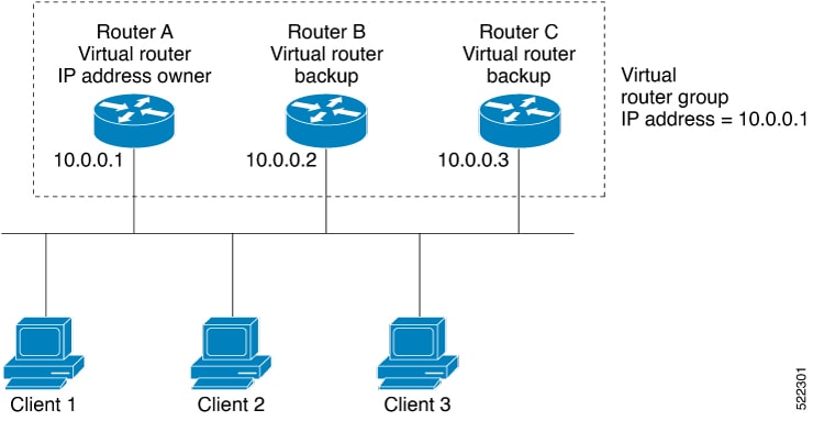
For example, Basic VRRP Topology shows a LAN topology in which VRRP is configured. In this example, Routers A, B, and C are VRRP routers (routers running VRRP) that compose a virtual router. The IP address of the virtual router is the same as that configured
for the interface of Router A (10.0.0.1).
Figure 1. Basic VRRP Topology
Because the virtual router uses the IP address of the physical interface of Router A, Router A assumes the role of the IP address owner and is responsible for forwarding packets that are sent to the VRRP group IP address. Clients 1 through 3 are configured
with the default gateway IP address of 10.0.0.1.
Routers B and C function as backup virtual routers. If the router that is IP address owner fails, the router that is configured with the higher priority becomes the IP address
owner and provides uninterrupted service for the LAN hosts. When Router A recovers, it becomes the IP address owner again.
Note
We recommend that you disable Spanning Tree Protocol (STP) on switch ports to which the virtual routers are connected. Enable
RSTP or rapid-PVST on the switch interfaces if the switch supports these protocols.
Multiple Virtual
Router Support
You can configure up to 255 virtual routers on a router interface. The actual number of virtual routers that a router interface
can support depends on the following factors:
Router
processing capability
Router memory
capability
Router interface
support of multiple MAC addresses
In a topology where multiple virtual routers are configured on a router interface, the interface can act as an IP address
owner for one or more virtual routers and as a backup for one or more virtual routers.
VRRP Router
Priority
An important aspect of the VRRP redundancy scheme is VRRP router priority. Priority determines the role that each VRRP router
plays and what happens if the IP address owner virtual router fails.
If a VRRP router owns the IP address of the virtual router and the IP address of the physical interface, this router functions
as a IP address owner virtual router.
If no VRRP router owns the IP address, the priority of a VRRP router, combined with the reempt settings, determines if a VRRP
router functions as an IP address owner router or a backup virtual router. By default, the highest priority VRRP router functions
as IP address owner router, and all the others function as backups. Priority also determines the order of ascendancy to becoming
an IP address owner virtual router if the IP address owner virtual router fails. You can configure the priority of each backup
virtual router with a value of 1 through 254, using the vrrp priority command.
For example, if Router A, the IP address owner virtual router in a LAN topology, fails, an election process takes place to
determine if backup virtual Routers B or C should take over. If Routers B and C are configured with the priorities of 101
and 100, respectively, Router B is elected to become IP address owner virtual router because it has the higher priority. If
Routers B and C are both configured with the priority of 100, the backup virtual router with the higher IP address is elected
to become the IP address owner virtual router.
By default, a preemptive scheme is enabled whereby a higher-priority backup virtual router that becomes available takes over
from the current IP address owner virtual router. You can disable this preemptive scheme using the vrrp preempt disable command.
If preemption is disabled, the backup virtual router that is elected to become IP address owner router upon the failure of
the original higher priority IP address owner router, remains the IP address owner router even if the original IP address
owner virtual router recovers and becomes available again.
VRRP
Advertisements
The IP address owner virtual router sends VRRP advertisements to other VRRP routers in the same group. The advertisements
communicate the priority and state of the IP address owner virtual router. The VRRP advertisements are encapsulated in IP
packets and sent to the IP Version 4 multicast address assigned to the VRRP group. The advertisements are sent every second
by default; the interval is configurable.
Benefits of
VRRP
The benefits of VRRP
are as follows:
Redundancy— VRRP
enables you to configure multiple routers as the default gateway router, which
reduces the possibility of a single point of failure in a network.
Load Sharing—You
can configure VRRP in such a way that traffic to and from LAN clients can be
shared by multiple routers, thereby sharing the traffic load more equitably
among available routers.
Multiple Virtual
Routers—VRRP supports up to 100 virtual routers (VRRP groups) on a router
interface, subject to the platform supporting multiple MAC addresses. You can
configure up to 256 virtual routers on a router interface. Multiple virtual
router support enables you to implement redundancy and load sharing in your LAN
topology.
Multiple IP
Addresses—The virtual router can manage multiple IP addresses, including
secondary IP addresses. Therefore, if you have multiple subnets configured on
an Ethernet interface, you can configure VRRP on each subnet.
Preemption—The redundancy scheme of VRRP enables you to preempt a backup virtual router that has taken over for a failing
IP address owner virtual router with a higher-priority backup virtual router that has become available.
Text
Authentication—You can ensure that VRRP messages received from VRRP routers
that comprise a virtual router are authenticated by configuring a simple text
password.
Advertisement
Protocol—VRRP uses a dedicated Internet Assigned Numbers Authority (IANA)
standard multicast address (224.0.0.18) for VRRP advertisements. This
addressing scheme minimizes the number of routers that must service the
multicasts and allows test equipment to accurately identify VRRP packets on a
segment. The IANA assigns VRRP the IP protocol number 112.
Hot
Restartability for VRRP
In the event of failure of a VRRP process in one group, forced failovers in peer VRRP IP address owner router groups should
be prevented. Hot restartability supports warm RP failover without incurring forced failovers to peer VRRP routers.
Unicast VRRP
You can now configure VRRP to support Layer 3 unicast transport, allowing it to enhance its capacity to send data to cloud
networks. Pairwise router redundancy enables high availability in cloud network scenarios. The default route of the cloud
native function needs a virtual IP (VIP) address because the paired routers do not have a pre-designated active member. Though
HSRP provides a VIP, the cloud networks do not support Layer 2 multicast or broadcast transports. To overcome the limitations
of Layer 2 multicast and broadcast transports, configure VRRP in Layer 3 unicast mode to support Layer 3 unicast transport.
This feature also enables VRRP to communicate state transition notifications using event-driven telemetry.
VRRP over BVI
Table 1. Feature History Table
Feature Name
Release Information
Feature Description
VRRP over BVI
Release 7.5.2
Virtual Router Redundancy Protocol (VRRP) runs on top of interfaces
of multiple routers in the same home network that has both Cisco and
other vendor routers. It allows a group of routers to behave as a
single virtual default gateway router, thereby providing default
gateway redundancy and minimizing traffic loss. VRRP now supports
Bridge-Group Virtual Interface (BVI), which means that VRRP sessions
can run between BVI interfaces of multiple routers.
The Virtual Router Redundancy Protocol (VRRP) protocol provides default gateway
redundancy for a LAN. It allows a group of routers to behave as a single virtual default
gateway router. In the group of routers, the router that has the highest VRRP priority
acts as the primary router and the remaining routers act as backup routers.
Bridge-Group Virtual Interface (BVI) is a virtual interface which provides Layer 3 or
routed functionality to a bridge group. Layer 2 functionality is applicable to the
interfaces which are part of a bridge group and BVI is the routed interface for that
bridge group.
Usually, VRRP sessions run on top of interfaces of the multiple routers which are in the
same home network. You can configure VRRP session only over BVI.
Topology
This topology showcases how VRRP functions over BVI.
In this topology, PE1 and PE2 are paired in a redundant group. This group provides
Layer 3 gateway service to CE1 and CE2. VRRP is configured over BVI interfaces on
PE1 and PE2. VRRP ensures one BVI is the active gateway. The other is the standby
gateway.
You can configure one of the BVIs to be active and the other BVI as standby by
setting the VRRP priority value. The active BVI is programmed with the virtual MAC
address chosen by VRRP. Hosts, CE1 and CE2 send the traffic to the virtual
destination MAC address and the active BVI forwards the traffic.
During failover, the standby BVI becomes active and is programmed with the virtual
MAC address. The traffic from the hosts is forwarded through this active BVI.
Supported Scale and Systems
VRRP over Bridge Virtual Interfaces (BVIs) is supported:
On the Cisco Silicon One Q100 ASIC-based systems and Cisco Silicon One Q200 ASIC-based systems. You can configure upto 512
HSRP groups (IPv4 and IPv6 combined) over BVIs on both the Cisco Silicon One Q100 systems and Cisco Silicon One Q200 systems.
Where the underlay IRB bridge domains consist of bridge members on L2 main or subinterfaces. Only physical and bundle interfaces
are supported for L2 bridging in IRB.
When both IPv4 and IPv6 are configured on a BVI interface, IPv4 and IPv6 each requires a session. A total of two sessions
are consumed on a BVI interface.
For IPv4 and IPv6 configurations, in both the default and VRF tables.
On both the fixed and distributed systems.
Restrictions
Consider these restrictions before you configure VRRP over BVIs.
The minimum supported VRRP Hello timer is 100 ms. At the minimum timer, a total of 50 sessions are supported. Above 100 ms
timers, the sessions scale goes up proportionately. A maximum of 255 VRRP groups and 510 sessions are supported.
Configure VRRP over BVI
To configure VRRP sessions over BVI, you must complete the following configurations on
PE1 and PE2:
Configure a set of interfaces as Layer 2 interfaces and a set of VLAN
sub-interfaces.
Configure a bridge group.
Configure a BVI.
Configure VRRP over BVI.
Configuration Example
/* Enter the global configuration mode and configure a set of interfaces as Layer 2 interfaces and a set of VLAN sub-interfaces */
Router# configure
Router(config)# interface HundredGigE0/0/1/0.1 l2transport
Router(config-subif)# encapsulation dot1q 1
Router(config-subif)# rewrite ingress tag pop 1 symmetric
Router(config-subif)# commit
Router(config-subif)# exit
Router(config)# interface HundredGigE0/0/1/1.1 l2transport
Router(config-subif)# encapsulation dot1q 1
Router(config-subif)# rewrite ingress tag pop 1 symmetric
Router(config-subif)# commit
Router(config-subif)# exit

/* Enter the Layer 2 VPN configuration mode and configure a bridge group */
Router(config)# l2vpn
Router(config-l2vpn)# bridge group 5
Router(config-l2vpn-bg)# bridge-domain 5
Router(config-l2vpn-bg-bd)# interface HundredGigE0/0/1/0.1
Router(config-l2vpn-bg-bd-ac)# exit
Router(config-l2vpn-bg-bd)# interface HundredGigE0/0/1/1.1
Router(config-l2vpn-bg-bd-ac)# exit
Router(config-l2vpn-bg-bd)# routed interface BVI 10
Router(config-l2vpn-bg-bd-bvi)# commit
Router(config-l2vpn-bg-bd-bvi)# exit

/* Configure a BVI in the global configuration mode */
Router(config)# interface BVI 10

Router(config-if)# ipv4 address 209.165.200.225 255.255.255.0
Router(config-if)# ipv6 address 2001:DB8:A:B::1/64
Router(config-if)# commit

/* Configure VRRP over BVI in the global configuration mode for IPv4 address */
Router(config)# router VRRP
Router(config-vrrp)# interface BVI 10
Router(config-vrrp-if)# address-family ipv4
Router(config-vrrp-address-family)# VRRP 10
Router(config-vrrp-virtual-router)# priority 101
Router(config-vrrp-virtual-router)# address 209.165.200.226
Router(config-vrrp-virtual-router)# commit


/* Configure VRRP over BVI in the global configuration mode for IPv6 address */
Router(config)# router VRRP
Router(config-vrrp)# interface BVI 10
Router(config-vrrp-if)# address-family ipv6
Router(config-vrrp-address-family)# VRRP 11
Router(config-vrrp-virtual-router)# address global 2001:DB8:A:B::2
Router(config-vrrp-virtual-router)#  address linklocal autoconfig
Router(config-vrrp-virtual-router)# commit
Verification
Use the following command to verify the bridge domain details:
Router# show l2vpn bridge-domain detail

Legend: pp = Partially Programmed.
Bridge group: 5, bridge-domain: 5, id: 1, state: up, ShgId: 0, MSTi: 0
Coupled state: disabled
VINE state: BVI Resolved
MAC learning: enabled
MAC withdraw: enabled
MAC withdraw for Access PW: enabled
MAC withdraw sent on: bridge port up
MAC withdraw relaying (access to access): disabled
Flooding:
Broadcast & Multicast: enabled
Unknown unicast: enabled
MAC aging time: 300 s, Type: inactivity
MAC limit: 32768, Action: none, Notification: syslog
MAC limit reached: no, threshold: 75%
MAC port down flush: enabled
MAC Secure: disabled, Logging: disabled
Split Horizon Group: none
Dynamic ARP Inspection: disabled, Logging: disabled
IP Source Guard: disabled, Logging: disabled
DHCPv4 Snooping: disabled
DHCPv4 Snooping profile: none
IGMP Snooping: disabled
IGMP Snooping profile: none
MLD Snooping profile: none
Storm Control: disabled
Bridge MTU: 1500
MIB cvplsConfigIndex: 2
Filter MAC addresses:
P2MP PW: disabled
Multicast Source: Not Set
Create time: 26/05/2020 17:08:54 (00:11:30 ago)
No status change since creation
ACs: 3 (3 up), VFIs: 0, PWs: 0 (0 up), PBBs: 0 (0 up), VNIs: 0 (0 up)
List of ACs:
AC: BVI10, state is up
Type Routed-Interface
MTU 1514; XC ID 0x80000001; interworking none
BVI MAC address:
c472.95a6.8b90
Virtual MAC addresses:
0000.5e00.010a
0000.5e00.020b
Split Horizon Group: Access
AC: HundredGigE0/0/1/0.1, state is up
Type VLAN; Num Ranges: 1
Rewrite Tags: []
VLAN ranges: [1, 1]
MTU 1500; XC ID 0x1; interworking none
MAC learning: enabled
Use the following command to show the VRRP details:
Router# show vrrp ipv4 detailBVI10 - IPv4 vrID 10
State is Master
2 state changes, last state change 00:11:57
State change history:
May 26 17:08:59.470 UTC Init -> Backup Delay timer expired
May 26 17:09:03.075 UTC Backup -> Master Master down timer expired
Last resign sent: NeverLast resign received: Never
Virtual IP address is 209.165.200.226
Virtual MAC address is 0000.5E00.010a, state is active
Master router is local
Version is 2
Advertise time 1 secs
Master Down Timer 3.605 (3 x 1 + (155 x 1/256))
Minimum delay 1 sec, reload delay 5 sec
Current priority 101
Configured priority 101, may preempt
minimum delay 0 secs
Router# show vrrp ipv6 detail

BVI10 - IPv6 vrID 11
State is Master
2 state changes, last state change 00:04:29
State change history:
May 26 17:16:43.476 UTC Init -> Backup Virtual IP configured
May 26 17:16:47.085 UTC Backup -> Master Master down timer expired
Last resign sent: Never
Last resign received: Never
Virtual IP address is fe80::200:5eff:fe00:20b
Secondary Virtual IP address is 2001:db8:a:b::2
Virtual MAC address is 0000.5E00.020b, state is active
Master router is local
Version is 3
Advertise time 1 secs
Master Down Timer 3.609 (3 x 1 + (156 x 1/256))
Minimum delay 1 sec, reload delay 5 sec
Current priority 100
Configured priority 100, may preempt
minimum delay 0 secs
Router# show vrrp interface BVI10 detail
BVI10 - IPv4 vrID 10
State is Master
2 state changes, last state change 00:12:35
State change history:
May 26 17:08:59.470 UTC Init -> Backup Delay timer expired
May 26 17:09:03.075 UTC Backup -> Master Master down timer expired
Last resign sent: Never
Last resign received: Never
Virtual IP address is 209.165.200.226
Virtual MAC address is 0000.5E00.010a, state is active
Master router is local
Version is 2
Advertise time 1 secs
Master Down Timer 3.605 (3 x 1 + (155 x 1/256))
Minimum delay 1 sec, reload delay 5 sec
Current priority 101
Configured priority 101, may preempt
minimum delay 0 secs

BVI10 - IPv6 vrID 11
State is Master
2 state changes, last state change 00:04:51
State change history:
May 26 17:16:43.476 UTC Init -> Backup Virtual IP configured
May 26 17:16:47.085 UTC Backup -> Master Master down timer expired
Last resign sent: Never
Last resign received: Never
Virtual IP address is fe80::200:5eff:fe00:20b
Secondary Virtual IP address is 2001:db8:a:b::2
Virtual MAC address is 0000.5E00.020b, state is active
Master router is local
Version is 3
Advertise time 1 secs
Master Down Timer 3.609 (3 x 1 + (156 x 1/256))
Minimum delay 1 sec, reload delay 5 sec
Current priority 100
Configured priority 100, may preempt
minimum delay 0 secs
View VRRP statistics in the Router
Table 2. Feature History Table
Feature Name
Release Information
Feature Description
View VRRP statistics in Router
Release 7.9.1
With this feature, you can view or clear statistics of one or all Virtual Router Redundancy Protocol (VRRP) groups or Virtual
Router IDs (VRIDs). This information helps you monitor VRRP health in the routers. It’s also helpful in debugging VRRP issues
like packet exchange failures when all virtual routers in the VRRP topology function as backup virtual routers and there’s
no IP address owner.


 Feedback