Implementing MPLS Traffic Engineering
Traditional IP routing emphasizes on forwarding traffic to the destination as fast as possible. As a result, the routing protocols find out the least-cost route according to its metric to each destination in the network and every router forwards the packet based on the destination IP address and packets are forwarded hop-by-hop. Thus, traditional IP routing does not consider the available bandwidth of the link. This can cause some links to be over-utilized compared to others and bandwidth is not efficiently utilized. Traffic Engineering (TE) is used when the problems result from inefficient mapping of traffic streams onto the network resources. Traffic engineering allows you to control the path that data packets follow and moves traffic flows from congested links to non-congested links that would not be possible by the automatically computed destination-based shortest path.
Multiprotocol Label Switching (MPLS) with its label switching capabilities, eliminates the need for an IP route look-up and creates a virtual circuit (VC) switching function, allowing enterprises the same performance on their IP-based network services as with those delivered over traditional networks such as Frame Relay or Asynchronous Transfer Mode (ATM). MPLS traffic engineering (MPLS-TE) relies on the MPLS backbone to replicate and expand upon the TE capabilities of Layer 2 ATM and Frame Relay networks.
MPLS-TE learns the topology and resources available in a network and then maps traffic flows to particular paths based on resource requirements and network resources such as bandwidth. MPLS-TE builds a unidirectional tunnel from a source to a destination in the form of a label switched path (LSP), which is then used to forward traffic. The point where the tunnel begins is called the tunnel headend or tunnel source, and the node where the tunnel ends is called the tunnel tailend or tunnel destination. A router through which the tunnel passes is called the mid-point of the tunnel.
MPLS uses extensions to a link-state based Interior Gateway Protocol (IGP), such as Intermediate System-to-Intermediate System (IS-IS) or Open Shortest Path First (OSPF). MPLS calculates TE tunnels at the LSP head based on required and available resources (constraint-based routing). If configured, the IGP automatically routes the traffic onto these LSPs. Typically, a packet that crosses the MPLS-TE backbone travels on a single LSP that connects the ingress point to the egress point. MPLS TE automatically establishes and maintains the LSPs across the MPLS network by using the Resource Reservation Protocol (RSVP).
 Note |
Combination of unlabelled paths protected by labelled paths is not supported. |
Overview of MPLS-TE Features
In MPLS traffic engineering, IGP extensions flood the TE information across the network. Once the IGP distributes the link attributes and bandwidth information, the headend router calculates the best path from head to tail for the MPLS-TE tunnel. This path can also be configured explicitly. Once the path is calculated, RSVP-TE is used to set up the TE LSP (Labeled Switch Path).
To forward the traffic, you can configure autoroute, forward adjacency, or static routing. The autoroute feature announces the routes assigned by the tailend router and its downstream routes to the routing table of the headend router and the tunnel is considered as a directly connected link to the tunnel.
If forward adjacency is enabled, MPLS-TE tunnel is advertised as a link in an IGP network with the link's cost associated with it. Routers outside of the TE domain can see the TE tunnel and use it to compute the shortest path for routing traffic throughout the network.
MPLS-TE provides protection mechanism known as fast reroute to minimize packet loss during a failure. For fast reroute, you need to create back up tunnels. The autotunnel backup feature enables a router to dynamically build backup tunnels when they are needed instead of pre-configuring each backup tunnel and then assign the backup tunnel to the protected interfaces.
DiffServ Aware Traffic Engineering (DS-TE) enables you to configure multiple bandwidth constraints on an MPLS-enabled interface to support various classes of service (CoS). These bandwidth constraints can be treated differently based on the requirement for the traffic class using that constraint.
The MPLS traffic engineering auto-tunnel mesh feature allows you to set up full mesh of TE tunnels automatically with a minimal set of MPLS traffic engineering configurations. The MPLS-TE auto bandwidth feature allows you to automatically adjusts bandwidth based on traffic patterns without traffic disruption.
The MPLS-TE interarea tunneling feature allows you to establish TE tunnels spanning multiple Interior Gateway Protocol (IGP) areas and levels, thus eliminating the requirement that headend and tailend routers should reside in a single area.
For detailed information about MPLS-TE features, see MPLS-TE Features - Details.
How MPLS-TE Works
MPLS-TE automatically establishes and maintains label switched paths (LSPs) across the backbone by using RSVP. The path that an LSP uses is determined by the LSP resource requirements and network resources, such as bandwidth. Available resources are flooded by extensions to a link state based Interior Gateway Protocol (IGP). MPLS-TE tunnels are calculated at the LSP headend router, based on a fit between the required and available resources (constraint-based routing). The IGP automatically routes the traffic to these LSPs. Typically, a packet crossing the MPLS-TE backbone travels on a single LSP that connects the ingress point to the egress point.
The following sections describe the components of MPLS-TE:
Tunnel Interfaces
From a Layer 2 standpoint, an MPLS tunnel interface represents the headend of an LSP. It is configured with a set of resource requirements, such as bandwidth and media requirements, and priority. From a Layer 3 standpoint, an LSP tunnel interface is the headend of a unidirectional virtual link to the tunnel destination.
MPLS-TE Path Calculation Module
This calculation module operates at the LSP headend. The module determines a path to use for an LSP. The path calculation uses a link-state database containing flooded topology and resource information.
RSVP with TE Extensions
RSVP operates at each LSP hop and is used to signal and maintain LSPs based on the calculated path.
MPLS-TE Link Management Module
This module operates at each LSP hop, performs link call admission on the RSVP signaling messages, and keep track on topology and resource information to be flooded.
Link-state IGP
Either Intermediate System-to-Intermediate System (IS-IS) or Open Shortest Path First (OSPF) can be used as IGPs. These IGPs are used to globally flood topology and resource information from the link management module.
Label Switching Forwarding
This forwarding mechanism provides routers with a Layer 2-like ability to direct traffic across multiple hops of the LSP established by RSVP signaling.
Configuring MPLS-TE
MPLS-TE requires co-ordination among several global neighbor routers. RSVP, MPLS-TE and IGP are configured on all routers and interfaces in the MPLS traffic engineering network. Explicit path and TE tunnel interfaces are configured only on the head-end routers. MPLS-TE requires some basic configuration tasks explained in this section.
Building MPLS-TE Topology
Building MPLS-TE topology, sets up the environment for creating MPLS-TE tunnels. This procedure includes the basic node and interface configuration for enabling MPLS-TE. To perform constraint-based routing, you need to enable OSPF or IS-IS as IGP extension.
Before You Begin
Before you start to build the MPLS-TE topology, the following pre-requisites are required:
-
Stable router ID is required at either end of the link to ensure that the link is successful. If you do not assign a router ID, the system defaults to the global router ID. Default router IDs are subject to change, which can result in an unstable link.
-
Enable RSVP on the port interface.
Example
This example enables MPLS-TE on a node and then specifies the interface that is part of the MPLS-TE. Here, OSPF is used as the IGP extension protocol for information distribution.
RP/0/RP0/CPU0:router# configure
RP/0/RP0/CPU0:router(config)# mpls traffic-eng
RP/0/RP0/CPU0:router(config-mpls-te)# interface hundredGigE0/0/0/3
RP/0/RP0/CPU0:router(config)# router ospf area 1
RP/0/RP0/CPU0:router(config-ospf)# area 0
RP/0/RP0/CPU0:router(config-ospf-ar)# mpls traffic-eng
RP/0/RP0/CPU0:router(config-ospf-ar)# interface hundredGigE0/0/0/3
RP/0/RP0/CPU0:router(config-ospf-ar-if)# exit
RP/0/RP0/CPU0:router(config-ospf)# mpls traffic-eng router-id 192.168.70.1
RP/0/RP0/CPU0:router(config)# commit
Example
This example enables MPLS-TE on a node and then specifies the interface that is part of the MPLS-TE. Here, IS-IS is used as the IGP extension protocol for information distribution.
RP/0/RP0/CPU0:router# configure
RP/0/RP0/CPU0:router(config)# mpls traffic-eng
RP/0/RP0/CPU0:router(config-mpls-te)# interface hundredGigE0/0/0/3
RP/0/RP0/CPU0:router(config)# router isis 1
RP/0/RP0/CPU0:router(config-isis)# net 47.0001.0000.0000.0002.00
RP/0/RP0/CPU0:router(config-isis)# address-family ipv4 unicast
RP/0/RP0/CPU0:router(config-isis-af)# metric-style wide
RP/0/RP0/CPU0:router(config-isis-af)# mpls traffic-eng level 1
RP/0/RP0/CPU0:router(config-isis-af)# exit
RP/0/RP0/CPU0:router(config-isis)# interface hundredGigE0/0/0/3
RP/0/RP0/CPU0:router(config-isis-if)# exit
RP/0/RP0/CPU0:router(config)# commit
Related Topics
Creating an MPLS-TE Tunnel
Creating an MPLS-TE tunnel is a process of customizing the traffic engineering to fit your network topology. The MPLS-TE tunnel is created at the headend router. You need to specify the destination and path of the TE LSP.
To steer traffic through the tunnel, you can use the following ways:
-
Static Routing
-
Autoroute Announce
-
Forwarding Adjacency
From the 7.1.1 release, IS-IS autoroute announce function is enhanced to redirect traffic from a source IP address prefix to a matching IP address assigned to an MPLS-TE tunnel destination interface.
Before You Begin
The following prerequisites are required to create an MPLS-TE tunnel:
-
You must have a router ID for the neighboring router.
-
Stable router ID is required at either end of the link to ensure that the link is successful. If you do not assign a router ID to the routers, the system defaults to the global router ID. Default router IDs are subject to change, which can result in an unstable link.
Configuration Example
This example configures an MPLS-TE tunnel on the headend router with a destination IP address 192.168.92.125. The bandwidth for the tunnel, path-option, and forwarding parameters of the tunnel are also configured. You can use static routing, autoroute announce or forwarding adjacency to steer traffic through the tunnel.
RP/0/RP0/CPU0:router# configure
RP/0/RP0/CPU0:router(config)# interface tunnel-te 1
RP/0/RP0/CPU0:router(config-if)# destination 192.168.92.125
RP/0/RP0/CPU0:router(config-if)# ipv4 unnumbered Loopback0
RP/0/RP0/CPU0:router(config-if)# path-option 1 dynamic
RP/0/RP0/CPU0:router(config-if)# autoroute announce  or forwarding adjacency
RP/0/RP0/CPU0:router(config-if)# signalled-bandwidth 100
RP/0/RP0/CPU0:router(config)# commit
Verification
Verify the configuration of MPLS-TE tunnel using the following command.
RP/0/RP0/CPU0:router# show mpls traffic-engineering tunnels brief

  				      Signalling Summary:
		              LSP Tunnels Process:  running
		                     RSVP Process:  running
		                       Forwarding:  enabled
		          Periodic reoptimization:  every 3600 seconds, next in 2538 seconds
		           Periodic FRR Promotion:  every 300 seconds, next in 38 seconds
		          Auto-bw enabled tunnels:  0 (disabled)
		                     TUNNEL NAME         DESTINATION      STATUS  STATE


                      tunnel-te1       192.168.92.125      up       up
            Displayed 1 up, 0 down, 0 recovering, 0 recovered heads
Automatic Modification Of An MPLS-TE Tunnel’s Metric
If the IGP calculation on a router results in an equal cost multipath (ECMP) scenario where next-hop interfaces are a mix of MPLS-TE tunnels and physical interfaces, you may want to ensure that a TE tunnel is preferred. Consider this topology:

-
All links in the network have a metric of 5.
-
To offload a congested link between R3 and R4, an MPLS-TE tunnel is created from R3 to R2.
-
If the metric of the tunnel is also 5, traffic from R3 to R5 is load-balanced between the tunnel and the physical R3-R4 link.
To ensure that the MPLS-TE tunnel is preferred in such scenarios, configure the autoroute metric command on the tunnel interface. The modified metric is applied in the routing information base (RIB), and the tunnel is preferred over the physical path of the same metric. Sample configuration:
Router# configure
Router(config)# interface tunnel-te 1
Router(config-if)# autoroute metric relative -1
The autoroute metric command syntax is autoroute metric {absolute|relative} value
-
absolute enables the absolute metric mode, for a metric range between 1 and 2147483647.
-
relative enables the relative metric mode, for a metric range between -10 and 10, including zero.
Note |
Since the relative metric is not saved in the IGP database, the advertised metric of the MPLS-TE tunnel remains 5, and doesn't affect SPF calculation outcomes on other nodes. |
Related Topics
Configuring Fast Reroute
Fast reroute (FRR) provides link protection to LSPs enabling the traffic carried by LSPs that encounter a failed link to be rerouted around the failure. The reroute decision is controlled locally by the router connected to the failed link. The headend router on the tunnel is notified of the link failure through IGP or through RSVP. When it is notified of a link failure, the headend router attempts to establish a new LSP that bypasses the failure. This provides a path to reestablish links that fail, providing protection to data transfer. The path of the backup tunnel can be an IP explicit path, a dynamically calculated path, or a semi-dynamic path. For detailed conceptual information on fast reroute, see MPLS-TE Features - Details
Before You Begin
The following prerequisites are required to create an MPLS-TE tunnel:
-
You must have a router ID for the neighboring router.
-
Stable router ID is required at either end of the link to ensure that the link is successful. If you do not assign a router ID to the routers, the system defaults to the global router ID. Default router IDs are subject to change, which can result in an unstable link.
Configuration Example
This example configures fast reroute on an MPLS-TE tunnel. Here, tunnel-te 2 is configured as the back-up tunnel. You can use the protected-by command to configure path protection for an explicit path that is protected by another path.
RP/0/RP0/CPU0:router # configure
RP/0/RP0/CPU0:router(config)# interface tunnel-te 1
RP/0/RP0/CPU0:router(config-if)# fast-reroute
RP/0/RP0/CPU0:router(config-if)# exit
RP/0/RP0/CPU0:router(config)# mpls traffic-eng
RP/0/RP0/CPU0:router(config-mpls-te)# interface HundredGigabitEthernet0/0/0/3
RP/0/RP0/CPU0:router(config-mpls-te-if)# backup-path tunnel-te 2
RP/0/RP0/CPU0:router(config)# interface tunnel-te 2
RP/0/RP0/CPU0:router(config-if)# backup-bw global-pool 5000
RP/0/RP0/CPU0:router(config-if)# ipv4 unnumbered Loopback0
RP/0/RP0/CPU0:router(config-if)# destination 192.168.92.125
RP/0/RP0/CPU0:router(config-if)# path-option l explicit name backup-path protected by 10
RP/0/RP0/CPU0:router(config-if)# path-option l0 dynamic
RP/0/RP0/CPU0:router(config)# commit
Verification
Use the show mpls traffic-eng fast-reroute database command to verify the fast reroute configuration.
RP/0/RP0/CPU0:router# show mpls traffic-eng fast-reroute database

Tunnel head FRR information:
Tunnel      Out intf/label                      FRR intf/label      Status
----------  ----------------                    ----------------    -------
tt4000       HundredGigabitEthernet 0/0/0/3:34     tt1000:34        Ready
tt4001       HundredGigabitEthernet 0/0/0/3:35     tt1001:35        Ready
tt4002       HundredGigabitEthernet 0/0/0/3:36     tt1001:36        Ready
Related Topics
Configuring Auto-Tunnel Backup
|
Feature Name |
Release Information |
Feature Description |
|---|---|---|
|
Bandwidth Protection Functions to Enhance auto-tunnel backup Capabilities |
Release 7.5.1 |
This feature introduces bandwidth protection functions for auto-tunnel backups, such as signaled bandwidth, bandwidth protection, and soft-preemption. These functions provide better bandwidth usage and prevent traffic congestion and traffic loss. In earlier releases, auto-tunnel backups provided only link protection and node protection. Backup tunnels were signaled with zero bandwidth, causing traffic congestion when FRR went active. This feature introduces the following commands and keywords: |
The MPLS Traffic Engineering Auto-Tunnel Backup feature enables a router to dynamically build backup tunnels on the interfaces that are configured with MPLS TE tunnels instead of building MPLS-TE tunnels statically.
The MPLS-TE Auto-Tunnel Backup feature has these benefits:
-
Backup tunnels are built automatically, eliminating the need for users to pre-configure each backup tunnel and then assign the backup tunnel to the protected interface.
-
Protection is expanded—FRR does not protect IP traffic that is not using the TE tunnel or Label Distribution Protocol (LDP) labels that are not using the TE tunnel.
The TE attribute-set template that specifies a set of TE tunnel attributes, is locally configured at the headend of auto-tunnels. The control plane triggers the automatic provisioning of a corresponding TE tunnel, whose characteristics are specified in the respective attribute-set.
Configuration Example
This example configures Auto-Tunnel backup on an interface and specifies the attribute-set template for the auto tunnels. In this example, unused backup tunnels are removed every 20 minutes using a timer and also the range of tunnel interface numbers are specified.
RP/0/RP0/CPU0:router # configure
RP/0/RP0/CPU0:router(config)# mpls traffic-eng
RP/0/RP0/CPU0:router(config-mpls-te)# interface HundredGigabitEthernet0/0/0/3
RP/0/RP0/CPU0:router(config-mpls-te-if)# auto-tunnel backup
RP/0/RP0/CPU0:router(config-mpls-te-if-auto-backup)# attribute-set ab
RP/0/RP0/CPU0:router(config-mpls-te)# auto-tunnel backup timers removal unused 20
RP/0/RP0/CPU0:router(config-mpls-te)# auto-tunnel backup tunnel-id min 6000 max 6500
RP/0/RP0/CPU0:router(config)# commit
Verification
RP/0/RP0/CPU0:router# show mpls traffic-eng tunnels brief

            TUNNEL NAME         DESTINATION      STATUS  STATE
             tunnel-te0           200.0.0.3          up  up
             tunnel-te1           200.0.0.3          up  up
             tunnel-te2           200.0.0.3          up  up
             tunnel-te50          200.0.0.3          up  up
           *tunnel-te60        200.0.0.3          up  up
              *tunnel-te70        200.0.0.3          up  up
              *tunnel-te80        200.0.0.3          up  up
Related Topics
Bandwidth Protection Functions to Enhance auto-tunnel backup Capabilities
Without bandwidth protection, auto-tunnel backups provide only link protection and node protection (per next-next-hop), and backup tunnels are signalled with zero bandwidth. This causes traffic congestion when FRR goes active, since the backup tunnels might be protecting huge amount of data, such as LSPs with large bandwidth or multiple LSPs.
To address the congestion issue, bandwidth protection capabilities are added for auto-tunnel backups. Bandwidth protection, signalled bandwidth, and soft-preemption settings are provided. Details:-
Bandwidth protection – A link or node protection backup might not provide bandwidth protection. But with this setting (bandwidth-protection maximum-aggregate), you can set the maximum bandwidth value that an auto-tunnel can protect.
-
Signalled bandwidth – Without bandwidth protection, auto-tunnel backups are signaled with zero bandwidth too, with no guarantee that at least some bandwidth is backed up. So, the backup tunnels might be setup on links that are highly utilized, causing congestion drops when the backup tunnels start to transmit traffic after FRR is triggered.
This setting (signalled-bandwidth) addresses the issue, since you can set the signalled bandwidth of the tunnel (and reserve minimal bandwidth for an auto-tunnel backup). When you set the signal bandwidth value for auto-backup tunnels, congestion over backup links reduces.
-
Soft-preemption – Since bandwidth can be reserved for autobackup tunnels, a setting (soft-preemption) is provided for soft-preemption of the reserved bandwidth, if it is needed for a higher-priority tunnel.
Configurations
/*Enable Bandwidth Protection On a TE Auto-Tunnel Backup*/
Router # configure
Router(config)# mpls traffic-eng
Router(config-mpls-te)# interface GigabitEthernet 0/2/0/0 auto-tunnel backup
Router(config-te-if-auto-backup)# bandwidth-protection maximum-aggregate 100000
Router(config-te-if-auto-backup)# commit
/*Enable Signalled Bandwidth On a TE Auto-Tunnel Backup*/
Router # configure
Router(config)# mpls traffic-eng attribute-set auto-backup MyBackupConfig
Router(config-te-attribute-set)# signalled-bandwidth 700000
Router(config-te-attribute-set)# commit
After creating the auto backup attribute-set (MyBackupConfig in this case), associate with the auto-tunnel backup interface.
Router# configure
Router(config)# mpls traffic-eng
Router(config-mpls-te)# interface GigabitEthernet 0/2/0/0 auto-tunnel backup
Router(config-te-if-auto-backup)# attribute-set MyBackupConfig
Router(config-te-if-auto-backup)# auto-tunnel backup tunnel-id min 6000 max 6500
Router(config-mpls-te)# commit
/*Enable Soft-Preemption Bandwidth On a TE Auto-Tunnel Backup*/
Router# configure
Router(config)# mpls traffic-eng attribute-set auto-backup MyBackupConfig
Router(config-te-attribute-set)# soft-preemption
Router(config-te-attribute-set)# commit
Verification
/*Verify Auto-Tunnel Backup Configuration*/
In the output, bandwidth protection details are displayed, as denoted by BW.
Router# show mpls traffic-eng auto-tunnel backup

AutoTunnel Backup Configuration:
    Interfaces count: 1
    Unused removal timeout: 1h 0m 0s
    Configured tunnel number range: 6000-6500

AutoTunnel Backup Summary:
    AutoTunnel Backups:
             0 created, 0 up, 0 down, 0 unused
             0 NHOP, 0 NNHOP, 0 SRLG strict, 0 SRLG preferred, 0 SRLG weighted, 0 BW protected
  Protected LSPs:
             0 NHOP, 0 NHOP+SRLG, 0 NHOP+BW, 0 NHOP+BW+SRLG
             0 NNHOP, 0 NNHOP+SRLG, 0 NNHOP+BW, 0 NNHOP+BW+SRLG
    Protected S2L Sharing Families:
             0 NHOP, 0 NHOP+SRLG, 0 NNHOP+BW, 0 NNHOP+BW+SRLG
             0 NNHOP, 0 NNHOP+SRLG, 0 NNHOP+BW, 0 NNHOP+BW+SRLG
    Protected S2Ls:
             0 NHOP, 0 NHOP+SRLG, 0 NNHOP+BW, 0 NNHOP+BW+SRLG
             0 NNHOP, 0 NNHOP+SRLG, 0 NNHOP+BW, 0 NNHOP+BW+SRLG

 Cumulative Counters (last cleared 00:08:47 ago):
                         Total   NHOP  NNHOP
    Created:               0       0      0
    Connected:             0       0      0
    Removed (down):        0       0      0
    Removed (unused):      0       0      0
    Removed (in use):      0       0      0
    Range exceeded:        0       0      0
Configuring Next Hop Backup Tunnel
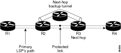
The backup tunnels that bypass only a single link of the LSP path are referred as Next Hop (NHOP) backup tunnels because they terminate at the LSP's next hop beyond the point of failure. They protect LSPs, if a link along their path fails, by rerouting the LSP traffic to the next hop, thus bypassing the failed link.
Configuration Example
This example configures next hop backup tunnel on an interface and specifies the attribute-set template for the auto tunnels. In this example, unused backup tunnels are removed every 20 minutes using a timer and also the range of tunnel interface numbers are specified.
RP/0/RP0/CPU0:router # configure
RP/0/RP0/CPU0:router(config)# mpls traffic-eng
RP/0/RP0/CPU0:router(config-mpls-te)# interface HundredGigabitEthernet0/0/0/3
RP/0/RP0/CPU0:router(config-mpls-te-if)# auto-tunnel backup nhop-only
RP/0/RP0/CPU0:router(config-mpls-te-if-auto-backup)# attribute-set ab
RP/0/RP0/CPU0:router(config-mpls-te)# auto-tunnel backup timers removal unused 20
RP/0/RP0/CPU0:router(config-mpls-te)# auto-tunnel backup tunnel-id min 6000 max 6500
RP/0/RP0/CPU0:router(config)# commit
Related Topics
Configuring SRLG Node Protection
Shared Risk Link Groups (SRLG) in MPLS traffic engineering refer to situations in which links in a network share common resources. These links have a shared risk, and that is when one link fails, other links in the group might fail too.
OSPF and IS-IS flood the SRLG value information (including other TE link attributes such as bandwidth availability and affinity) using a sub-type length value (sub-TLV), so that all routers in the network have the SRLG information for each link.
MPLS-TE SRLG feature enhances backup tunnel path selection by avoiding using links that are in the same SRLG as the interfaces it is protecting while creating backup tunnels.
Configuration Example
This example creates a backup tunnel and excludes the protected node IP address from the explicit path.
RP/0/RP0/CPU0:router # configure
RP/0/RP0/CPU0:router(config)# mpls traffic-eng
RP/0/RP0/CPU0:router(config-mpls-te)# interface HundredGigabitEthernet0/0/0/3
RP/0/RP0/CPU0:router(config-mpls-te-if)# backup-path tunnl-te 2
RP/0/RP0/CPU0:router(config-mpls-te-if)# exit
RP/0/RP0/CPU0:router(config)# interface tunnel-te 2
RP/0/RP0/CPU0:router(config-if)# ipv4 unnumbered Loopback0
RP/0/RP0/CPU0:router(config-if)# path-option 1 explicit name backup-srlg
RP/0/RP0/CPU0:router(config-if)# destination 192.168.92.125
RP/0/RP0/CPU0:router(config-if)# exit
RP/0/RP0/CPU0:router(config)# explicit-path name backup-srlg-nodep
RP/0/RP0/CPU0:router(config-if)# index 1 exclude-address 192.168.91.1
RP/0/RP0/CPU0:router(config-if)# index 2 exclude-srlg 192.168.92.2
RP/0/RP0/CPU0:router(config)# commit
Related Topics
Configuring Pre-Standard DS-TE
Regular traffic engineering does not provide bandwidth guarantees to different traffic classes. A single bandwidth constraint is used in regular TE that is shared by all traffic. MPLS DS-TE enables you to configure multiple bandwidth constraints on an MPLS-enabled interface. These bandwidth constraints can be treated differently based on the requirement for the traffic class using that constraint. Cisco IOS XR software supports two DS-TE modes: Pre-standard and IETF. Pre-standard DS-TE uses the Cisco proprietary mechanisms for RSVP signaling and IGP advertisements. This DS-TE mode does not interoperate with third-party vendor equipment. Pre-standard DS-TE is enabled only after configuring the sub-pool bandwidth values on MPLS-enabled interfaces.
Pre-standard Diff-Serve TE mode supports a single bandwidth constraint model a Russian Doll Model (RDM) with two bandwidth pools: global-pool and sub-pool.
Before You Begin
The following prerequisites are required to configure a Pre-standard DS-TE tunnel.
-
You must have a router ID for the neighboring router.
-
Stable router ID is required at either end of the link to ensure that the link is successful. If you do not assign a router ID to the routers, the system defaults to the global router ID. Default router IDs are subject to change, which can result in an unstable link.
Configuration Example
This example configures a pre-standard DS-TE tunnel.
RP/0/RP0/CPU0:router # configure
RP/0/RP0/CPU0:router(config)# rsvp interface HundredGigabitEthernet 0/0/0/3
RP/0/RP0/CPU0:router(config-rsvp-if)# bandwidth 100 150 sub-pool 50
RP/0/RP0/CPU0:router(config-rsvp-if)# exit
RP/0/RP0/CPU0:router(config)# interface tunnel-te 2
RP/0/RP0/CPU0:router(config-if)# signalled bandwidth sub-pool 10
RP/0/RP0/CPU0:router(config)# commit
Verification
Use the show mpls traffic-eng topology command to verify the pre-standard DS-TE tunnel configuration.
Related Topics
Configuring an IETF DS-TE Tunnel Using RDM
IETF DS-TE mode uses IETF-defined extensions for RSVP and IGP. This mode interoperate with third-party vendor equipment.
IETF mode supports multiple bandwidth constraint models, including Russian Doll Model (RDM) and Maximum Allocation Model (MAM), both with two bandwidth pools. In an IETF DS-TE network, identical bandwidth constraint models must be configured on all nodes.
Before you Begin
The following prerequisites are required to create a IETF mode DS-TE tunnel using RDM:
-
You must have a router ID for the neighboring router.
-
Stable router ID is required at either end of the link to ensure that the link is successful. If you do not assign a router ID to the routers, the system defaults to the global router ID. Default router IDs are subject to change, which can result in an unstable link.
Configuration Example
This example configures an IETF DS-TE tunnel using RDM.
RP/0/RP0/CPU0:router # configure
RP/0/RP0/CPU0:router(config)# rsvp interface HundredGigabitEthernet 0/0/0/3
RP/0/RP0/CPU0:router(config-rsvp-if)# bandwidth rdm 100 150
RP/0/RP0/CPU0:router(config-rsvp-if)# exit
RP/0/RP0/CPU0:router(config)# mpls traffic-eng
RP/0/RP0/CPU0:router(config-mpls-te)# ds-te mode ietf
RP/0/RP0/CPU0:router(config-mpls-te)# exit
RP/0/RP0/CPU0:router(config)# interface tunnel-te 2
RP/0/RP0/CPU0:router(config-if)# signalled bandwidth sub-pool 10 class-type 1
RP/0/RP0/CPU0:router(config)# commit
Verification
Use the show mpls traffic-eng topology command to verify the IETF DS-TE tunnel using RDM configuration.
Related Topics
Configuring an IETF DS-TE Tunnel Using MAM
IETF DS-TE mode uses IETF-defined extensions for RSVP and IGP. This mode interoperates with third-party vendor equipment. IETF mode supports multiple bandwidth constraint models, including Russian Doll Model (RDM) and Maximum Allocation Model (MAM), both with two bandwidth pools.
Configuration Example
This example configures an IETF DS-TE tunnel using MAM.
RP/0/RP0/CPU0:router # configure
RP/0/RP0/CPU0:router(config)# rsvp interface HundredGigabitEthernet 0/0/0/3
RP/0/RP0/CPU0:router(config-rsvp-if)# bandwidth mam max-reservable-bw 1000 bc0 600 bc1 400
RP/0/RP0/CPU0:router(config-rsvp-if)# exit
RP/0/RP0/CPU0:router(config)# mpls traffic-eng
RP/0/RP0/CPU0:router(config-mpls-te)# ds-te mode ietf
RP/0/RP0/CPU0:router(config-mpls-te)# ds-te bc-model mam
RP/0/RP0/CPU0:router(config-mpls-te)# exit
RP/0/RP0/CPU0:router(config)# interface tunnel-te 2
RP/0/RP0/CPU0:router(config-if)# signalled bandwidth sub-pool 10
RP/0/RP0/CPU0:router(config)# commit
Verification
Use the show mpls traffic-eng topology command to verify the IETF DS-TE tunnel using MAM configuration.
Related Topics
Configuring Flexible Name-Based Tunnel Constraints
MPLS-TE Flexible Name-based Tunnel Constraints provides a simplified and more flexible means of configuring link attributes and path affinities to compute paths for the MPLS-TE tunnels.
In traditional TE, links are configured with attribute-flags that are flooded with TE link-state parameters using Interior Gateway Protocols (IGPs), such as Open Shortest Path First (OSPF).
MPLS-TE Flexible Name-based Tunnel Constraints lets you assign, or map, up to 32 color names for affinity and attribute-flag attributes instead of 32-bit hexadecimal numbers. After mappings are defined, the attributes can be referred to by the corresponding color name.
Configuration Example
This example shows assigning a how to associate a tunnel with affinity constraints.
RP/0/RP0/CPU0:router# configure
RP/0/RP0/CPU0:router(config)# mpls traffic-eng
RP/0/RP0/CPU0:router(config-mpls-te)# affinity-map red 1
RP/0/RP0/CPU0:router(config-mpls-te)# interface HundredGigabitEthernet0/0/0/3
RP/0/RP0/CPU0:router(config-mpls-te-if)# attribute-names red
RP/0/RP0/CPU0:router(config)# interface tunnel-te 2
RP/0/RP0/CPU0:router(config-if)# affinity include red
RP/0/RP0/CPU0:router(config)# commit
Configuring Automatic Bandwidth
Automatic bandwidth allows you to dynamically adjust bandwidth reservation based on measured traffic. MPLS-TE automatic bandwidth monitors the traffic rate on a tunnel interface and resizes the bandwidth on the tunnel interface to align it closely with the traffic in the tunnel. MPLS-TE automatic bandwidth is configured on individual Label Switched Paths (LSPs) at every headend router.
The following table specifies the parameters that can be configured as part of automatic bandwidth configuration.
|
Bandwidth Parameters |
Description |
|---|---|
|
Application frequency |
Configures how often the tunnel bandwidths changed for each tunnel. The default value is 24 hours. |
|
Bandwidth limit |
Configures the minimum and maximum automatic bandwidth to set on a tunnel. |
|
Bandwidth collection frequency |
Enables bandwidth collection without adjusting the automatic bandwidth. The default value is 5 minutes. |
|
Overflow threshold |
Configures tunnel overflow detection. |
|
Adjustment threshold |
Configures the tunnel-bandwidth change threshold to trigger an adjustment. |
Configuration Example
This example enables automatic bandwidth on MPLS-TE tunnel interface and configure the following automatic bandwidth variables.
-
Application frequency
-
Bandwidth limit
-
Adjustment threshold
-
Overflow detection
RP/0/RP0/CPU0:router# configure
RP/0/RP0/CPU0:router(config)# interface tunnel-te 1
RP/0/RP0/CPU0:router(config-if)# auto-bw
RP/0/RP0/CPU0:router(config-if-tunte-autobw)# application 1000
RP/0/RP0/CPU0:router(config-if-tunte-autobw)# bw-limit min 30 max 1000
RP/0/RP0/CPU0:router(config-if-tunte-autobw)# adjustment-threshold 50 min 800
RP/0/RP0/CPU0:router(config-if-tunte-autobw)# overflow threshold 100 limit 1
RP/0/RP0/CPU0:router(config)# commit
Verification
Verify the automatic bandwidth configuration using the show mpls traffic-eng tunnels auto-bw brief command.
RP/0/RP0/CPU0:router# show mpls traffic-eng tunnels auto-bw brief

  Tunnel    LSP  Last appl  Requested  Signalled    Highest    Application
  Name       ID   BW(kbps)   BW(kbps)   BW(kbps)   BW(kbps)      Time Left
  -------------- ------ ---------- ---------- ---------- ---------- --------------
  tunnel-te1      5          500         300        420          1h 10m
Related Topics
Configuring Autoroute Announce
The segment routing tunnel can be advertised into an Interior Gateway Protocol (IGP) as a next hop by configuring the autoroute announce statement on the source router. The IGP then installs routes in the Routing Information Base (RIB) for shortest paths that involve the tunnel destination. Autoroute announcement of IPv4 prefixes can be carried through either OSPF or IS-IS. Autoroute announcement of IPv6 prefixes can be carried only through IS-IS. IPv6 forwarding over tunnel needs additional parameter in tunnel configuration.
Restrictions
The Autoroute Announce feature is supported with the following restrictions:
-
A maximum on 128 tunnels can be announced.
-
Tunnels in ECMP may not be path diverse.
Configuration
To specify that the Interior Gateway Protocol (IGP) should use the tunnel (if the tunnel is up) in its enhanced shortest path first (SPF) calculation, use the autoroute announce command in interface configuration mode.
RP/0/RP0/CPU0:router# configure
RP/0/RP0/CPU0:router(config)# interface tunnel-te 10
RP/0/RP0/CPU0:router(config-if)# autoroute announce [include-ipv6]
RP/0/RP0/CPU0:router(config-if)# commit
Verification
Verify the route using the following commands:
RP/0/RP0/CPU0:router# Show route
Mon Aug  8 00:31:29.406 UTC

Codes: C - connected, S - static, R - RIP, B - BGP, (>) - Diversion path
       D - EIGRP, EX - EIGRP external, O - OSPF, IA - OSPF inter area
       N1 - OSPF NSSA external type 1, N2 - OSPF NSSA external type 2
       E1 - OSPF external type 1, E2 - OSPF external type 2, E - EGP
       i - ISIS, L1 - IS-IS level-1, L2 - IS-IS level-2
       ia - IS-IS inter area, su - IS-IS summary null, * - candidate default
       U - per-user static route, o - ODR, L - local, G  - DAGR, l - LISP
       A - access/subscriber, a - Application route
       M - mobile route, r - RPL, (!) - FRR Backup path

Gateway of last resort is not set

i L1 9.1.0.0/24 [115/30] via 9.9.9.9, 2d19h, tunnel-te3195
                [115/30] via 9.9.9.9, 2d19h, tunnel-te3196
                [115/30] via 9.9.9.9, 2d19h, tunnel-te3197
                [115/30] via 9.9.9.9, 2d19h, tunnel-te3198
                [115/30] via 9.9.9.9, 2d19h, tunnel-te3199
                [115/30] via 9.9.9.9, 2d19h, tunnel-te3200
                [115/30] via 9.9.9.9, 2d19h, tunnel-te3201
                [115/30] via 9.9.9.9, 2d19h, tunnel-te3202
i L1 9.9.9.9/32 [115/30] via 9.9.9.9, 2d22h, tunnel-te3195
                [115/30] via 9.9.9.9, 2d22h, tunnel-te3196
                [115/30] via 9.9.9.9, 2d22h, tunnel-te3197
                [115/30] via 9.9.9.9, 2d22h, tunnel-te3198
                [115/30] via 9.9.9.9, 2d22h, tunnel-te3199
                [115/30] via 9.9.9.9, 2d22h, tunnel-te3200
                [115/30] via 9.9.9.9, 2d22h, tunnel-te3201
[115/30] via 9.9.9.9, 2d22h, tunnel-te3202RP/0/RP0/CPU0:router# show route ipv6
Tue Apr 26 04:02:07.968 UTC
Codes: C - connected, S - static, R - RIP, B - BGP, (>) - Diversion path
D - EIGRP, EX - EIGRP external, O - OSPF, IA - OSPF inter area
N1 - OSPF NSSA external type 1, N2 - OSPF NSSA external type 2
E1 - OSPF external type 1, E2 - OSPF external type 2, E - EGP
i - ISIS, L1 - IS-IS level-1, L2 - IS-IS level-2
ia - IS-IS inter area, su - IS-IS summary null, * - candidate default
U - per-user static route, o - ODR, L - local, G - DAGR, l - LISP
A - access/subscriber, a - Application route
M - mobile route, r - RPL, (!) - FRR Backup path
Gateway of last resort is not set
L ::ffff:127.0.0.0/104
[0/0] via ::, 00:17:36
C 2002::/64 is directly connected,
00:39:01, TenGigE0/0/0/2
L 2002::1/128 is directly connected,
00:39:01, TenGigE0/0/0/2
i L1 2003::/64
[115/20] via ::, 00:02:32, tunnel-te992
[115/20] via ::, 00:02:32, tunnel-te993
[115/20] via ::, 00:02:32, tunnel-te994
[115/20] via ::, 00:02:32, tunnel-te995
[115/20] via ::, 00:02:32, tunnel-te996
[115/20] via ::, 00:02:32, tunnel-te997
[115/20] via ::, 00:02:32, tunnel-te998
[115/20] via ::, 00:02:32, tunnel-te999
C 2006::/64 is directly connected,
00:39:01, TenGigE0/0/0/6
L 2006::1/128 is directly connected,
00:39:01, TenGigE0/0/0/6
i L1 2007::/64
[115/20] via ::, 00:02:32, tunnel-te992
[115/20] via ::, 00:02:32, tunnel-te993
[115/20] via ::, 00:02:32, tunnel-te994
[115/20] via ::, 00:02:32, tunnel-te995
[115/20] via ::, 00:02:32, tunnel-te996
[115/20] via ::, 00:02:32, tunnel-te997
[115/20] via ::, 00:02:32, tunnel-te998
[115/20] via ::, 00:02:32, tunnel-te999
show cef ipv6 2007::5 hardware egress location 0/0/CPU0
Sun May  1 03:18:55.151 UTC 2007::/64, version 50, internal 0x1000001 0x0 (ptr 0x895e819c) [1], 0x0 (0x894d3678), 0x0 (0x0)  Updated May  1 03:13:49.066  Prefix Len 64, traffic index 0, precedence n/a, priority 2
   via ::/128, tunnel-te1, 2 dependencies, weight 0, class 0 [flags 0x0]
    path-idx 0 NHID 0x0 [0x8b5ea420 0x0]
    next hop ::/128
    local adjacency
   via ::/128, tunnel-te2, 2 dependencies, weight 0, class 0 [flags 0x0]
    path-idx 1 NHID 0x0 [0x8b5ea5e0 0x0]
    next hop ::/128
    local adjacency


 LEAF - HAL pd context :
 sub-type : IPV6, ecd_marked:0, has_collapsed_ldi:0  collapse_bwalk_required:0, ecdv2_marked:0 HW Walk:
LEAF:
    Handle: 0xaabbccdd type: 1 FEC handle: 0x8999fb18

    LWLDI:
        PI:0x894d3678 PD:0x894d36b8 rev:214 p-rev:212 ldi type:3
        FEC hdl: 0x8999fb18 fec index: 0x0(0) num paths:2, bkup: 0

        SHLDI:
            PI:0x893658e8 PD:0x89365968 rev:212 p-rev:0 flag:0x0
            FEC hdl: 0x8999fb18 fec index: 0x20000002(2) num paths: 2 bkup paths: 2
            Path:0 fec index: 0x20004000(16384) DSP:0x440 Dest fec index: 0x2000101c(4124)
            Path:1 fec index: 0x20004002(16386) DSP:0x440 Dest fec index: 0x2000101c(4124)
            Path:2 fec index: 0x20004001(16385) DSP:0x440 Dest fec index: 0x2000101c(4124)
            Path:3 fec index: 0x20004003(16387) DSP:0x440 Dest fec index: 0x2000101c(4124)

V6TE NH HAL PD context :
pdptr 0x8b5ea488, flags :1, index:0

              TE-NH:
              Flag: PHP HW Tun_O_Tun frr_active_chg te_protect_chg , PD(0x880d1640), Push: 0, Swap: 0, Link: 0
              ifhandle:0x800001c llabel:24001 FEC hdl: 0x896d4eb8 fec index: 0x20001022(4130), SRTE fec hdl:(nil)

V6TE NH HAL PD context :
pdptr 0x8b5ea648, flags :1, index:0

              TE-NH:
              Flag: PHP HW , PD(0x880d12d0), Push: 0, Swap: 0, Link: 0x8b34d518
              ifhandle:0x8000024 llabel:24000 FEC hdl: 0x896d4238 fec index: 0x2000101c(4124), SRTE fec hdl:(nil)
Configuring Auto-Tunnel Mesh
The MPLS-TE auto-tunnel mesh (auto-mesh) feature allows you to set up full mesh of TE Point-to-Point (P2P) tunnels automatically with a minimal set of MPLS traffic engineering configurations. You can configure one or more mesh-groups and each mesh-group requires a destination-list (IPv4 prefix-list) listing destinations, which are used as destinations for creating tunnels for that mesh-group.
You can configure MPLS-TE auto-mesh type attribute-sets (templates) and associate them to mesh-groups. Label Switching Routers (LSRs) can create tunnels using the tunnel properties defined in this attribute-set.
Auto-Tunnel mesh configuration minimizes the initial configuration of the network. You can configure tunnel properties template and mesh-groups or destination-lists on TE LSRs that further creates full mesh of TE tunnels between those LSRs. It eliminates the need to reconfigure each existing TE LSR in order to establish a full mesh of TE tunnels whenever a new TE LSR is added in the network.
Configuration Example
This example configures an auto-tunnel mesh group and specifies the attributes for the tunnels in the mesh-group.
RP/0/RP0/CPU0:router # configure
RP/0/RP0/CPU0:router(config)# mpls traffic-eng
RP/0/RP0/CPU0:router(config-mpls-te)# auto-tunnel mesh
RP/0/RP0/CPU0:router(config-mpls-te-auto-mesh)# tunnel-id min 1000 max 2000
RP/0/RP0/CPU0:router(config-mpls-te-auto-mesh)# group 10
RP/0/RP0/CPU0:router(config-mpls-te-auto-mesh-group)# attribute-set 10
RP/0/RP0/CPU0:router(config-mpls-te-auto-mesh-group)# destination-list dl-65
RP/0/RP0/CPU0:router(config-mpls-te)# attribute-set auto-mesh 10
RP/0/RP0/CPU0:router(config-mpls-te-attribute-set)# autoroute announce
RP/0/RP0/CPU0:router(config-mpls-te-attribute-set)# auto-bw collect-bw-only
RP/0/RP0/CPU0:router(config)# commit
Verification
Verify the auto-tunnel mesh configuration using the show mpls traffic-eng auto-tunnel mesh command.
RP/0/RP0/CPU0:router# show mpls traffic-eng auto-tunnel mesh

Auto-tunnel Mesh Global Configuration:
  Unused removal timeout: 1h 0m 0s
  Configured tunnel number range: 1000-2000

Auto-tunnel Mesh Groups Summary:
  Mesh Groups count: 1
  Mesh Groups Destinations count: 3
  Mesh Groups Tunnels count:
    3 created, 3 up, 0 down, 0 FRR enabled

Mesh Group: 10 (3 Destinations)
  Status: Enabled
  Attribute-set: 10
  Destination-list: dl-65 (Not a prefix-list)
  Recreate timer: Not running
       Destination    Tunnel ID    State  Unused timer
  ----------------  -----------  -------  ------------
       192.168.0.2         1000     up   Not running
       192.168.0.3         1001     up   Not running
       192.168.0.4         1002     up   Not running
  Displayed 3 tunnels, 3 up, 0 down, 0 FRR enabled

Auto-mesh Cumulative Counters:
  Last cleared: Wed Oct  3 12:56:37 2015 (02:39:07 ago)
                      Total
  Created:                3
  Connected:              0
  Removed (unused):       0
  Removed (in use):       0
  Range exceeded:         0
Configuring an MPLS Traffic Engineering Interarea Tunneling
The MPLS TE Interarea Tunneling feature allows you to establish MPLS TE tunnels that span multiple Interior Gateway Protocol (IGP) areas and levels. This feature removes the restriction that required the tunnel headend and tailend routers both to be in the same area. The IGP can be either Intermediate System-to-Intermediate System (IS-IS) or Open Shortest Path First (OSPF).To configure an inter-area tunnel, you specify on the headend router a loosely routed explicit path for the tunnel label switched path (LSP) that identifies each area border router (ABR) the LSP should traverse using the next-address loose command. The headend router and the ABRs along the specified explicit path expand the loose hops, each computing the path segment to the next ABR or tunnel destination.
Configuration Example
This example configures an IPv4 explicit path with ABR configured as loose address on the headend router.
Router# configure
Router(config)# explicit-path name interarea1
Router(config-expl-path)# index1 next-address loose ipv4 unicast 172.16.255.129
Router(config-expl-path)# index 2 next-address loose ipv4 unicast 172.16.255.131
Router(config)# interface tunnel-te1
Router(config-if)# ipv4 unnumbered Loopback0
Router(config-if)# destination 172.16.255.2
Router(config-if)# path-option 10 explicit name interarea1
Router(config)# commit
Configuring LDP over MPLS-TE
LDP and RSVP-TE are signaling protocols used for establishing LSPs in MPLS networks. While LDP is easy to configure and reilable, it lacks the traffic engineering capabilities of RSVP that helps to avoid traffic congestions. LDP over MPLS-TE feature combines the benefits of both LDP and RSVP. In LDP over MPLS-TE, an LDP signalled label-switched path (LSP) runs through a TE tunnel established using RSVP-TE.
The following diagram explains a use case for LDP over MPLS-TE. In this diagram, LDP is used as the signalling protocol between provider edge (PE) router and provider (P) router. RSVP-TE is used as the signalling protocol between the P routers to establish an LSP. LDP is tunneled over the RSVP-TE LSP.

Restrictions and Guidelines for LDP over MPLS-TE
The following restrictions and guidelines apply for this feature in Cisco IOS-XR release 6.3.2:
-
MPLS services over LDP over MPLS-TE are supported when BGP neighbours are on the head or tail node of the TE tunnel.
-
MPLS services over LDP over MPLS-TE are supported when the TE headend router is acting as transit point for that service.
-
If MPLS services are originating from the TE headend, but the TE tunnel is ending before the BGP peer, LDP over MPLS-TE feature is not supported.
-
If LDP optimization is enabled using the hw-module fib mpls ldp lsr-optimized command, the following restrictions apply:
-
EVPN is not supported.
-
For any prefix or label all outgoing paths has to be LDP enabled.
-
-
Do not use the hw-module fib mpls ldp lsr-optimized command on a Provider Edge (PE) router because already configured features such as EVPN, MPLS-VPN, and L2VPN might not work properly.
Configuration Example:
This example shows how to configure an MPLS-TE tunnel from provider router P1 to P2 and then enbale LDP over MPLS-TE. In this example, the destination of the tunnel from P1 is configured as the loop back for P2.
RP/0/RP0/CPU0:router # configure
RP/0/RP0/CPU0:router(config)# interface tunnel-te 1
RP/0/RP0/CPU0:router(config-if)# ipv4 unnumbered Loopback0
RP/0/RP0/CPU0:router(config-if)# autoroute announce
RP/0/RP0/CPU0:router(config-if)# destination 4.4.4.4
RP/0/RP0/CPU0:router(config-if)# path-option 1 dynamic
RP/0/RP0/CPU0:router(config-if)# exit
RP/0/RP0/CPU0:Router(config)#  mpls ldp
RP/0/RP0/CPU0:Router(config-ldp)#  router-id 192.168.1.1
RP/0/RP0/CPU0:Router(config-ldp)#  interface TenGigE 0/0/0/0
RP/0/RP0/CPU0:Router(config-ldp-if)# interface tunnel-te 1
RP/0/RP0/CPU0:Router(config-ldp-if)# exit
Configuring MPLS-TE Path Protection
Path protection provides an end-to-end failure recovery mechanism for MPLS-TE tunnels. A secondary Label Switched Path (LSP) is established, in advance, to provide failure protection for the protected LSP that is carrying a tunnel's TE traffic. When there is a failure on the protected LSP, the source router immediately enables the secondary LSP to temporarily carry the tunnel's traffic. Failover is triggered by a RSVP error message sent to the LSP head end. Once the head end received this error message, it switches over to the secondary tunnel. If there is a failure on the secondary LSP, the tunnel no longer has path protection until the failure along the secondary path is cleared. Path protection can be used within a single area (OSPF or IS-IS), external BGP [eBGP], and static routes. Both the explicit and dynamic path-options are supported for the MPLS-TE path protection feature. You should make sure that the same attributes or bandwidth requirements are configured on the protected option.
Before You Begin
The following prerequisites are required for enabling path protection.
-
You should ensure that your network supports MPLS-TE, Cisco Express Forwarding, and Intermediate System-to-Intermediate System (IS-IS) or Open Shortest Path First (OSPF).
-
You should configure MPLS-TE on the routers.
Configuration Example
This example configures how to configure path protection for a mpls-te tunnel. The primary path-option should be present to configure path protection. In this configuration, R1 is the headend router and R3 is the tailend router for the tunnel while R2 and R4 are mid-point routers. In this example, 6 explicit paths and 1 dynamic path is created for path protection. You can have upto 8 path protection options for a primary path.
RP/0/RP0/CPU0:router # configure
RP/0/RP0/CPU0:router(config)# interface tunnel-te 0
RP/0/RP0/CPU0:router(config-if)# destination 192.168.3.3
RP/0/RP0/CPU0:router(config-if)# ipv4 unnumbered Loopback0
RP/0/RP0/CPU0:router(config-if)# autoroute announce
RP/0/RP0/CPU0:router(config-if)# path-protection
RP/0/RP0/CPU0:router(config-if)# path-option 1 explicit name r1-r2-r3-00 protected-by 2
RP/0/RP0/CPU0:router(config-if)# path-option 2 explicit name r1-r2-r3-01 protected-by 3
RP/0/RP0/CPU0:router(config-if)# path-option 3 explicit name r1-r4-r3-01 protected-by 4
RP/0/RP0/CPU0:router(config-if)# path-option 4 explicit name r1-r3-00 protected-by 5
RP/0/RP0/CPU0:router(config-if)# path-option 5 explicit name r1-r2-r4-r3-00 protected-by 6
RP/0/RP0/CPU0:router(config-if)# path-option 6 explicit name r1-r4-r2-r3-00 protected-by 7
RP/0/RP0/CPU0:router(config-if)# path-option 7 dynamic
RP/0/RP0/CPU0:router(config-if)# exit
RP/0/RP0/CPU0:router(config)# commit
Verification
Use the show mpls traffic-eng tunnels command to verify the MPLS-TE path protection configuration.
RP/0/RP0/CPU0:router# show mpls traffic-eng tunnels 0
Fri Oct 13 16:24:39.379 UTC
Name: tunnel-te0  Destination: 192.168.92.125  Ifhandle:0x8007d34
  Signalled-Name: router
  Status:
    Admin:    up Oper:   up   Path:  valid   Signalling: connected
    path option 1,  type explicit r1-r2-r3-00 (Basis for Setup, path weight 2)
      Protected-by PO index: 2
    path option 2,  type explicit r1-r2-r3-01 (Basis for Standby, path weight 2)
      Protected-by PO index: 3
    path option 3,  type explicit r1-r4-r3-01
      Protected-by PO index: 4
    path option 4,  type explicit r1-r3-00
      Protected-by PO index: 5
    path option 5,  type explicit r1-r2-r4-r3-00
      Protected-by PO index: 6
    path option 6,  type explicit r1-r4-r2-r3-00
      Protected-by PO index: 7
    path option 7,  type dynamic
    G-PID: 0x0800 (derived from egress interface properties)
    Bandwidth Requested: 0 kbps  CT0
    Creation Time: Fri Oct 13 15:05:28 2017 (01:19:11 ago)
  Config Parameters:
    Bandwidth:        0 kbps (CT0) Priority:  7  7 Affinity: 0x0/0xffff
    Metric Type: TE (global)
    Path Selection:
      Tiebreaker: Min-fill (default)
    Hop-limit: disabled
    Cost-limit: disabled
    Delay-limit: disabled
    Path-invalidation timeout: 10000 msec (default), Action: Tear (default)
    AutoRoute:  enabled  LockDown: disabled   Policy class: not set
    Forward class: 0 (not enabled)
    Forwarding-Adjacency: disabled
    Autoroute Destinations: 0
    Loadshare:          0 equal loadshares
    Auto-bw: disabled
    Fast Reroute: Disabled, Protection Desired: None
    Path Protection: Enabled
    BFD Fast Detection: Disabled
    Reoptimization after affinity failure: Enabled
    Soft Preemption: Disabled
  History:
    Tunnel has been up for: 01:14:13 (since Fri Oct 13 15:10:26 UTC 2017)
    Current LSP:
      Uptime: 01:14:13 (since Fri Oct 13 15:10:26 UTC 2017)
    Reopt. LSP:
      Last Failure:
        LSP not signalled, identical to the [CURRENT] LSP
        Date/Time: Fri Oct 13 15:08:41 UTC 2017 [01:15:58 ago]
    Standby Reopt LSP:
      Last Failure:
        LSP not signalled, identical to the [STANDBY] LSP
        Date/Time: Fri Oct 13 15:08:41 UTC 2017 [01:15:58 ago]
        First Destination Failed: 192.3.3.3
    Prior LSP:
      ID: 8 Path Option: 1
      Removal Trigger: path protection switchover
    Standby LSP:
      Uptime: 01:13:56 (since Fri Oct 13 15:10:43 UTC 2017)
  Path info (OSPF 1 area 0):
  Node hop count: 2
  Hop0: 192.168.1.2
  Hop1: 192.168.3.1
  Hop2: 192.168.3.2
  Hop3: 192.168.3.3
  Standby LSP Path info (OSPF 1 area 0), Oper State: Up :
  Node hop count: 2
  Hop0: 192.168.2.2
  Hop1: 192.168.3.1
  Hop2: 192.168.3.2
  Hop3: 192.168.3.3
Displayed 1 (of 4001) heads, 0 (of 0) midpoints, 0 (of 0) tails
Displayed 1 up, 0 down, 0 recovering, 0 recovered heads
MPLS-TE Features - Details
MPLS TE Fast Reroute Link and Node Protection
Fast Reroute (FRR) is a mechanism for protecting MPLS TE LSPs from link and node failures by locally repairing the LSPs at the point of failure, allowing data to continue to flow on them while their headend routers try to establish new end-to-end LSPs to replace them. FRR locally repairs the protected LSPs by rerouting them over backup tunnels that bypass failed links or node.
Note |
If FRR is greater than 50ms, it might lead to a loss of traffic. |
Backup tunnels that bypass only a single link of the LSP’s path provide link protection. They protect LSPs if a link along their path fails by rerouting the LSP’s traffic to the next hop (bypassing the failed link). These tunnels are referred to as next-hop (NHOP) backup tunnels because they terminate at the LSP’s next hop beyond the point of failure.
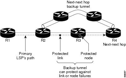
FRR provides node protection for LSPs. Backup tunnels that bypass next-hop nodes along LSP paths are called next-next-hop (NNHOP) backup tunnels because they terminate at the node following the next-hop node of the LSP paths, bypassing the next-hop node. They protect LSPs if a node along their path fails by enabling the node upstream of the failure to reroute the LSPs and their traffic around the failed node to the next-next hop. NNHOP backup tunnels also provide protection from link failures, because they bypass the failed link and the node.
Differentiated Services Traffic Engineering
MPLS Differentiated Services Aware Traffic Engineering (DS-TE) is an extension of the regular MPLS-TE feature. Regular traffic engineering does not provide bandwidth guarantees to different traffic classes. A single bandwidth constraint is used in regular TE that is shared by all traffic. To support various classes of service (CoS), you can configure multiple bandwidth constraints. These bandwidth constraints can be treated differently based on the requirement for the traffic class using that constraint.
Cisco IOS XR software supports two DS-TE modes: pre-standard and IETF. The pre-standard DS-TE mode uses the Cisco proprietary mechanisms for RSVP signaling and IGP advertisements. This DS-TE mode does not interoperate with third-party vendor equipment. Pre-standard DS-TE is enabled only after configuring the sub-pool bandwidth values on MPLS-enabled interfaces. Pre-standard DS-TE mode supports a single bandwidth constraint model a Russian Doll Model (RDM) with two bandwidth pools: global-pool and sub-pool. TE class map is not used with Pre-standard DS-TE mode.
IETF DS-TE mode uses IETF-defined extensions for RSVP and IGP. This mode inter-operates with third-party vendor equipment. IETF mode supports multiple bandwidth constraint models, including RDM and Maximum Allocation Bandwidth Constraint Model (MAM), both with two bandwidth pools. In an IETF DS-TE network, identical bandwidth constraint models must be configured on all nodes. TE class map is used with IETF DS-TE mode and must be configured the same way on all nodes in the network.
The MAM constraint model has the following characteristics:
- Easy to use and intuitive.
- Isolation across class types.
- Simultaneously achieves isolation, bandwidth efficiency, and protection against QoS degradation.
The RDM constraint model has these characteristics:
- Allows greater sharing of bandwidth among different class types.
- Ensures bandwidth efficiency simultaneously and protection against QoS degradation of all class types.
- Specifies that it is used with preemption to simultaneously achieve isolation across class-types such that each class-type is guaranteed its share of bandwidth, bandwidth efficiency, and protection against QoS degradation of all class types.
MPLS-TE Forwarding Adjacency
MPLS TE forwarding adjacency allows you to handle a TE label-switched path (LSP) tunnel as a link in an Interior Gateway Protocol (IGP) network that is based on the Shortest Path First (SPF) algorithm. Both Intermediate System-to-Intermediate System (IS-IS) and Open Shortest Path First (OSPF) are supported as the IGP. A forwarding adjacency can be created between routers regardless of their location in the network. The routers can be located multiple hops from each other.
As a result, a TE tunnel is advertised as a link in an IGP network with the tunnel's cost associated with it. Routers outside of the TE domain see the TE tunnel and use it to compute the shortest path for routing traffic throughout the network. TE tunnel interfaces are advertised in the IGP network just like any other links. Routers can then use these advertisements in their IGPs to compute the SPF even if they are not the headend of any TE tunnels.
Automatic Bandwidth
Automatic bandwidth allows you to dynamically adjust bandwidth reservation based on measured traffic. MPLS-TE automatic bandwidth is configured on individual Label Switched Paths (LSPs) at every headend router. MPLS-TE automatic bandwidth monitors the traffic rate on a tunnel interface and resizes the bandwidth on the tunnel interface to align it closely with the traffic in the tunnel.
- Monitors periodic polling of the tunnel output rate
- Resizes the tunnel bandwidth by adjusting the highest rate observed during a given period.
For every traffic-engineered tunnel that is configured for an automatic bandwidth, the average output rate is sampled, based on various configurable parameters. Then, the tunnel bandwidth is readjusted automatically based on either the largest average output rate that was noticed during a certain interval, or a configured maximum bandwidth value.
While re-optimizing the LSP with the new bandwidth, a new path request is generated. If the new bandwidth is not available, the last good LSP remains used. This way, the network experiences no traffic interruptions. If minimum or maximum bandwidth values are configured for a tunnel, the bandwidth, which the automatic bandwidth signals, stays within these values.
The output rate on a tunnel is collected at regular intervals that are configured by using the application command in MPLS-TE auto bandwidth interface configuration mode. When the application period timer expires, and when the difference between the measured and the current bandwidth exceeds the adjustment threshold, the tunnel is re-optimized. Then, the bandwidth samples are cleared to record the new largest output rate at the next interval. If a tunnel is shut down, and is later brought again, the adjusted bandwidth is lost, and the tunnel is brought back with the initially configured bandwidth. When the tunnel is brought back, the application period is reset.
MPLS Traffic Engineering Interarea Tunneling
The MPLS-TE interarea tunneling feature allows you to establish TE tunnels spanning multiple Interior Gateway Protocol (IGP) areas and levels, thus eliminating the requirement that headend and tailend routers reside in a single area.
Interarea support allows the configuration of a TE LSP that spans multiple areas, where its headend and tailend label switched routers (LSRs) reside in different IGP areas. Customers running multiple IGP area backbones (primarily for scalability reasons) requires Multiarea and Interarea TE . This lets you limit the amount of flooded information, reduces the SPF duration, and lessens the impact of a link or node failure within an area, particularly with large WAN backbones split in multiple areas.
The following figure shows a typical interarea TE network using OSPF.

The following figure shows a typical interlevel (IS-IS) TE Network.

As shown in the Interlevel (IS-IS) TE Network Diagram, R2, R3, R7, and R4 maintain two databases for routing and TE information. For example, R3 has TE topology information related to R2, flooded through Level-1 IS-IS LSPs plus the TE topology information related to R4, R9, and R7, flooded as Level 2 IS-IS Link State PDUs (LSPs) (plus, its own IS-IS LSP).
Loose hop optimization allows the re-optimization of tunnels spanning multiple areas and solves the problem which occurs when an MPLS-TE LSP traverses hops that are not in the LSP's headend's OSPF area and IS-IS level. Interarea MPLS-TE allows you to configure an interarea traffic engineering (TE) label switched path (LSP) by specifying a loose source route of ABRs along the path. Then it is the responsibility of the ABR (having a complete view of both areas) to find a path obeying the TE LSP constraints within the next area to reach the next hop ABR (as specified on the headend router). The same operation is performed by the last ABR connected to the tailend area to reach the tailend LSR.
- You must specify the router ID of the ABR node (as opposed to a link address on the ABR).
- When multiarea is deployed in a network that contains subareas, you must enable MPLS-TE in the subarea for TE to find a path when loose hop is specified.
- You must specify the reachable explicit path for the interarea tunnel.
UCMP Over MPLS-TE
In Equal Cost Multi Path (ECMP), you can load-balance routed traffic over multiple paths of the same cost. With Unequal-Cost Multipath (UCMP), you can load-balance traffic over multiple paths of varying costs.
Consider three forwarding links, with two 10 Gigabit Ethernet links and a 100 Gigabit Ethernet link, as shown in the image.
In such a scenario, the incoming traffic load is not equally distributed using ECMP. On the other hand, UCMP applies a weight to a path, and adds more forwarding instances to a path that has a higher weight (larger bandwidth). This results in an equal load distribution over paths of varying bandwidths (and costs).
Configuration Example
UCMP Configuration:
R1# configure
R1(config)# mpls traffic-eng
R1(config-mpls-te)# load-share unequal
R1(config-mpls-te)# commit
Tunnels Configuration:
R1(config)# interface tunnel-te 1
R1(config-if)# ipv4 unnumbered loopback 1
R1(config-if)# load-share 5
R1(config-if)# autoroute announce
R1(config-if-tunte-aa)# commit
R1(config-if-tunte-aa)# exit
R1(config-if)# destination 172.16.0.1
R1(config-if)# path-option 1 dynamic

R1(config)# interface tunnel-te 2
R1(config-if)# ipv4 address 192.168.0.1 255.255.255.0
R1(config-if)# load-share 6
R1(config-if)# autoroute announce
R1(config-if-tunte-aa)# commit
R1(config-if-tunte-aa)# exit
R1(config-if)# destination 172.16.0.1
R1(config-if)# path-option 1 dynamic
Associated Commands
Verification
Verify UCMP Configuration:
R1# show cef 172.16.0.1 detail

172.16.0.1/32, version 16, internal 0x1000001 0x0 (ptr 0x97de1a58) [1], 0x0 (0x97fa3728), 0xa20 (0x98fc00a8)
 Updated Jun 17 16:07:46.325
 Prefix Len 32, traffic index 0, precedence n/a, priority 3
  gateway array (0x97e0ba08) reference count 3, flags 0x68, source lsd (5), 1 backups
                [3 type 4 flags 0x8401 (0x9849f728) ext 0x0 (0x0)]
  LW-LDI[type=1, refc=1, ptr=0x97fa3728, sh-ldi=0x9849f728]
  gateway array update type-time 1 Jun 17 16:07:46.325
 LDI Update time Jun 17 16:07:46.350
 LW-LDI-TS Jun 17 16:07:46.350
   via 172.16.0.1/32, tunnel-te1, 5 dependencies, weight 100, class 0 [flags 0x0]
    path-idx 0 NHID 0x0 [0x98e19380 0x98e192f0]
    next hop 172.16.0.1/32
    local adjacency
     local label 24001      labels imposed {ImplNull}
   via 172.16.0.1/32, tunnel-te2, 7 dependencies, weight 10, class 0 [flags 0x0]
    path-idx 1 NHID 0x0 [0x98e194a0 0x98e19410]
    next hop 172.16.0.1/32
    local adjacency
     local label 24001      labels imposed {ImplNull}

    Weight distribution:

    slot 0, weight 100, normalized_weight 10, class 0
    slot 1, weight 10, normalized_weight 1, class 0
    Load distribution: 0 0 0 0 0 0 0 0 0 0 1 (refcount 3)

    Hash  OK  Interface                 Address
    0     Y   tunnel-te1                point2point
    1     Y   tunnel-te1                point2point
    2     Y   tunnel-te1                point2point
    3     Y   tunnel-te1                point2point
    4     Y   tunnel-te1                point2point
    5     Y   tunnel-te1                point2point
    6     Y   tunnel-te1                point2point
    7     Y   tunnel-te1                point2point
    8     Y   tunnel-te1                point2point
    9     Y   tunnel-te1                point2point
    10    Y   tunnel-te2                point2point
Some sample output:
Router# show run formal mpls traffic-eng

mpls traffic-eng
mpls traffic-eng interface Bundle-Ether2
mpls traffic-eng interface Bundle-Ether3
..
mpls traffic-eng load-share unequal
mpls traffic-eng reoptimize 180
mpls traffic-eng signalling advertise explicit-null
mpls traffic-eng reoptimize timers delay path-protection 60
Router# show run formal interface tunnel-te400

interface tunnel-te400
interface tunnel-te400 description TE-STI-GRTMIABR5-GRTBUEBA3-BW-0
interface tunnel-te400 ipv4 unnumbered Loopback0
interface tunnel-te400 load-interval 30
interface tunnel-te400 signalled-name TE-STI-GRTMIABR5-GRTBUEBA3-BW-0
interface tunnel-te400 load-share 80
interface tunnel-te400 autoroute destination 94.142.100.214
interface tunnel-te400 destination 94.142.100.214
interface tunnel-te400 path-protection
interface tunnel-te400 path-option 1 explicit name BR5-BA3-0 protected-by 2
interface tunnel-te400 path-option 2 explicit name BW-BR5-1-VAP3-BA3-0
interface tunnel-te400 path-option 3 explicit name BW-BR5-VAP3-BA3-0
Router# show run formal interface tunnel-te406

interface tunnel-te406
interface tunnel-te406 description TE-STI-GRTMIABR5-GRTBUEBA3-BW-20
interface tunnel-te406 ipv4 unnumbered Loopback0
interface tunnel-te406 load-interval 30
interface tunnel-te406 signalled-name TE-STI-GRTMIABR5-GRTBUEBA3-BW-20
interface tunnel-te406 load-share 10
interface tunnel-te406 autoroute destination 94.142.100.214
interface tunnel-te406 destination 94.142.100.214
interface tunnel-te406 path-protection
interface tunnel-te406 path-option 1 explicit name BR5-1-BA3-0 protected-by 2
interface tunnel-te406 path-option 2 explicit name BW-BR5-VAP4-BA3-0
Router# show cef 94.142.100.214/32 det

94.142.100.214/32, version 25708656, attached, internal 0x4004081 0x0 (ptr 0x764ff1b0) [3], 0x0 (0x7267d848), 0x440 (0x7d93b2b8)
 Updated Nov 19 08:02:26.545
 Prefix Len 32, traffic index 0, precedence n/a, priority 3
  gateway array (0x72411528) reference count 3, flags 0xd0, source lsd (4), 1 backups
                [3 type 4 flags 0x10101 (0x7300d648) ext 0x0 (0x0)]
  LW-LDI[type=1, refc=1, ptr=0x7267d848, sh-ldi=0x7300d648]
   via tunnel-te400, 3 dependencies, weight 80, class 0 [flags 0x8]
    path-idx 0 NHID 0x0 [0x72082a40 0x72983b58]
    local adjacency
     local label 16440      labels imposed {ImplNull}
   via tunnel-te406, 3 dependencies, weight 10, class 0 [flags 0x8]
    path-idx 1 NHID 0x0 [0x7207b4ac 0x729886bc]
    local adjacency
     local label 16440      labels imposed {ImplNull}
   via tunnel-te410, 3 dependencies, weight 80, class 0 [flags 0x8]
    path-idx 2 NHID 0x0 [0x72085218 0x72985ee4]
    local adjacency
     local label 16440      labels imposed {ImplNull}
   via tunnel-te426, 3 dependencies, weight 10, class 0 [flags 0x8]
    path-idx 3 NHID 0x0 [0x7207d4b4 0x7297fecc]
    local adjacency
     local label 16440      labels imposed {ImplNull}
   via tunnel-te427, 3 dependencies, weight 25, class 0 [flags 0x8]
    path-idx 4 NHID 0x0 [0x720802cc 0x7298726c]
    local adjacency
     local label 16440      labels imposed {ImplNull}
   via tunnel-te1089, 3 dependencies, weight 40, class 0 [flags 0x8]
    path-idx 5 NHID 0x0 [0x72081848 0x7298037c]
    local adjacency
     local label 16440      labels imposed {ImplNull}
   via tunnel-te1090, 3 dependencies, weight 60, class 0 [flags 0x8]
    path-idx 6 NHID 0x0 [0x7207d770 0x72987780]
    local adjacency
     local label 16440      labels imposed {ImplNull}
   via tunnel-te1099, 3 dependencies, weight 60, class 0 [flags 0x8]
    path-idx 7 NHID 0x0 [0x7207ed50 0x72981c7c]
    local adjacency
     local label 16440      labels imposed {ImplNull}

    Weight distribution:
    slot 0, weight 80, normalized_weight 7, class 0
    slot 1, weight 10, normalized_weight 1, class 0
    slot 2, weight 80, normalized_weight 7, class 0
    slot 3, weight 10, normalized_weight 1, class 0
    slot 4, weight 25, normalized_weight 1, class 0
    slot 5, weight 40, normalized_weight 3, class 0
    slot 6, weight 60, normalized_weight 5, class 0
    slot 7, weight 60, normalized_weight 5, class 0
Router# show cef 94.142.100.213/32 det

94.142.100.213/32, version 25708617, attached, internal 0x4004081 0x0 (ptr 0x771925c8) [3], 0x0 (0x7267a594), 0x440 (0x7d93d364)
 Updated Nov 19 08:02:01.029
 Prefix Len 32, traffic index 0, precedence n/a, priority 3
  gateway array (0x7240f638) reference count 3, flags 0xd0, source lsd (4), 1 backups
                [3 type 4 flags 0x10101 (0x73013360) ext 0x0 (0x0)]
  LW-LDI[type=1, refc=1, ptr=0x7267a594, sh-ldi=0x73013360]
   via tunnel-te220, 3 dependencies, weight 60, class 0 [flags 0x8]
    path-idx 0 NHID 0x0 [0x7207d838 0x72982af0]
    local adjacency
     local label 17561      labels imposed {ImplNull}
   via tunnel-te230, 3 dependencies, weight 60, class 0 [flags 0x8]
    path-idx 1 NHID 0x0 [0x7207d068 0x72986e20]
    local adjacency
     local label 17561      labels imposed {ImplNull}
   via tunnel-te236, 3 dependencies, weight 50, class 0 [flags 0x8]
    path-idx 2 NHID 0x0 [0x720830e4 0x7297f508]
    local adjacency
     local label 17561      labels imposed {ImplNull}
   via tunnel-te246, 3 dependencies, weight 100, class 0 [flags 0x8]
    path-idx 3 NHID 0x0 [0x7207a1ec 0x7298483c]
    local adjacency
     local label 17561      labels imposed {ImplNull}
   via tunnel-te221, 3 dependencies, weight 50, class 0 [flags 0x8]
    path-idx 4 NHID 0x0 [0x7207ea30 0x72982834]
    local adjacency
     local label 17561      labels imposed {ImplNull}
   via tunnel-te222, 3 dependencies, weight 25, class 0 [flags 0x8]
    path-idx 5 NHID 0x0 [0x72084a48 0x72989850]
    local adjacency
     local label 17561      labels imposed {ImplNull}
   via tunnel-te1091, 3 dependencies, weight 30, class 0 [flags 0x8]
    path-idx 6 NHID 0x0 [0x720851b4 0x729895f8]
    local adjacency
     local label 17561      labels imposed {ImplNull}
   via tunnel-te342, 3 dependencies, weight 100, class 0 [flags 0x8]
    path-idx 7 NHID 0x0 [0x72085344 0x7298b024]
    local adjacency
     local label 17561      labels imposed {ImplNull}

    Weight distribution:
    slot 0, weight 60, normalized_weight 2, class 0
    slot 1, weight 60, normalized_weight 2, class 0
    slot 2, weight 50, normalized_weight 2, class 0
    slot 3, weight 100, normalized_weight 4, class 0
    slot 4, weight 50, normalized_weight 2, class 0
    slot 5, weight 25, normalized_weight 1, class 0
    slot 6, weight 30, normalized_weight 1, class 0
    slot 7, weight 100, normalized_weight 4, class 0

    Load distribution: 0 0 1 1 2 2 3 3 3 3 4 4 5 6 7 7 7 7 (refcount 3)

    Hash  OK  Interface                 Address
    0     Y   tunnel-te220              point2point
    1     Y   tunnel-te220              point2point
    2     Y   tunnel-te230              point2point
    3     Y   tunnel-te230              point2point
    4     Y   tunnel-te236              point2point
    5     Y   tunnel-te236              point2point
    6     Y   tunnel-te246              point2point
    7     Y   tunnel-te246              point2point
    8     Y   tunnel-te246              point2point
    9     Y   tunnel-te246              point2point
    10    Y   tunnel-te221              point2point
    11    Y   tunnel-te221              point2point
    12    Y   tunnel-te222              point2point
    13    Y   tunnel-te1091             point2point
    14    Y   tunnel-te342              point2point
    15    Y   tunnel-te342              point2point
    16    Y   tunnel-te342              point2point
    17    Y   tunnel-te342              point2point
 Feedback