Information About Multiple Spanning Tree Protocol

To configure Multiple Spanning Tree Protocol, you must understand these concepts:

Spanning Tree Protocol Overview

Ethernet is no longer just a link-layer technology used to interconnect network vehicles and hosts. Its low cost and wide spectrum of bandwidth capabilities coupled with a simple plug and play provisioning philosophy have transformed Ethernet into a legitimate technique for building networks, particularly in the access and aggregation regions of service provider networks.

Ethernet networks lacking a TTL field in the Layer 2 (L2) header and, encouraging or requiring multicast traffic network-wide, are susceptible to broadcast storms if loops are introduced. However, loops are a desirable property as they provide redundant paths. Spanning tree protocols (STP) are used to provide a loop free topology within Ethernet networks, allowing redundancy within the network to deal with link failures.

There are many variants of STP; however, they work on the same basic principle. Within a network that may contain loops, a sufficient number of interfaces are disabled by STP so as to ensure that there is a loop-free spanning tree, that is, there is exactly one path between any two devices in the network. If there is a fault in the network that affects one of the active links, the protocol recalculates the spanning tree so as to ensure that all devices continue to be reachable. STP is transparent to end stations which cannot detect whether they are connected to a single LAN segment or to a switched LAN containing multiple segments and using STP to ensure there are no loops.

STP Protocol Operation

All variants of STP operate in a similar fashion: STP frames (known as bridge protocol data units (BPDUs)) are exchanged at regular intervals over Layer 2 LAN segments, between network devices participating in STP. Such network devices do not forward these frames, but use the information to construct a loop free spanning tree.

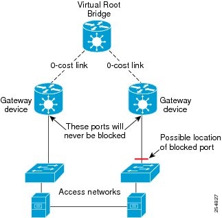
The spanning tree is constructed by first selecting a device which is the root of the spanning tree (known as the root bridge), and then by determining a loop free path from the root bridge to every other device in the network. Redundant paths are disabled by setting the appropriate ports into a blocked state, where STP frames can still be exchanged but data traffic is never forwarded. If a network segment fails and a redundant path exists, the STP protocol recalculates the spanning tree topology and activates the redundant path, by unblocking the appropriate ports.

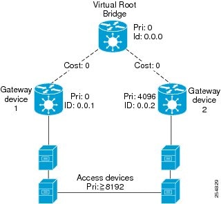
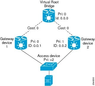
The selection of the root bridge within a STP network is determined by the lowest Bridge ID which is a combination of configured bridge priority and embedded mac address of each device. The device with the lowest priority, or with equal lowest priority but the lowest MAC address is selected as the root bridge.

Root port: is selected based on lowest root path cost to root bridge. If there is a tie with respect to the root path cost, port on local switch which receives BPDU with lowest sender bridge ID is selected as root port.

Designated port: Least cost port on local switch towards root bridge is selected as designated port. If there is a tie, lowest number port on local switch is selected as designated port.

The selection of the active path among a set of redundant paths is determined primarily by the port path cost. The port path cost represents the cost of transiting between that port and the root bridge - the further the port is from the root bridge, the higher the cost. The cost is incremented for each link in the path, by an amount that is (by default) dependent on the media speed. Where two paths from a given LAN segment have an equal cost, the selection is further determined by the lowest bridge ID of the attached devices, and in the case of two attachments to the same device, by the configured port priority and port ID of the neighboring attached ports.

Once the active paths have been selected, any ports that do not form part of the active topology are moved to the blocking state.

Topology Changes

Network devices in a switched LAN perform MAC learning; that is, they use received data traffic to associate unicast MAC addresses with the interface out of which frames destined for that MAC address should be sent. If STP is used, then a recalculation of the spanning tree (for example, following a failure in the network) can invalidate this learned information. The protocol therefore includes a mechanism to notify topology changes around the network, so that the stale information can be removed (flushed) and new information can be learned based on the new topology.

A Topology Change notification is sent whenever STP moves a port from the blocking state to the forwarding state. When it is received, the receiving device flushes the MAC learning entries for all ports that are not blocked other than the one where the notification was received, and also sends its own topology change notification out of those ports. In this way, it is guaranteed that stale information is removed from all the devices in the network.

Variants of STP

There are many variants of the Spanning Tree Protocol:

  • Legacy STP (STP)—The original STP protocol was defined in IEEE 802.1D-1998. This creates a single spanning tree which is used for all VLANs and most of the convergence is timer-based.

  • Rapid STP (RSTP)—This is an enhancement defined in IEEE 802.1D-2004 to provide more event-based, and hence faster, convergence. However, it still creates a single spanning tree for all VLANs.

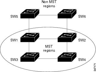
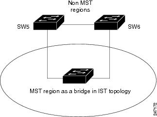
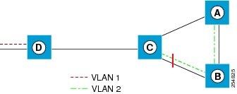
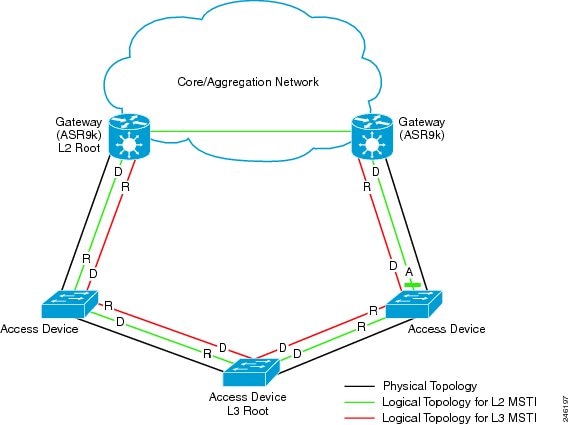
  • Multiple STP (MSTP)—A further enhancement was defined in IEEE 802.1Q-2005. This allows multiple spanning tree instances to be created over the same physical topology. By assigning different VLANs to the different spanning tree instances, data traffic can be load-balanced over different physical links. The number of different spanning tree instances that can be created is restricted to a much smaller number than the number of possible VLANs; however, multiple VLANs can be assigned to the same spanning tree instance. The BPDUs used to exchange MSTP information are always sent untagged; the VLAN and spanning tree instance data is encoded inside the BPDU.

  • Per-Vlan Rapid Spanning Tree (PVRST)— This feature is the IEEE 802.1w (RSTP) standard implemented per VLAN, and is also known as Rapid PVST or PVST+. A single instance of STP runs on each configured VLAN (if you do not manually disable STP). Each Rapid PVST+ instance on a VLAN has a single root switch. You can enable and disable STP on a per-VLAN basis when you are running Rapid PVST+.

    PVRST uses point-to-point wiring to provide rapid convergence of the spanning tree. The spanning tree reconfiguration can occur in less than one second with PVRST (in contrast to 50 seconds with the default settings in the 802.1D STP).

  • REP (Cisco-proprietary ring-redundancy protocol)— This is a Cisco-proprietary protocol for providing resiliency in rings. It is included for completeness, as it provides MSTP compatibility mode, using which, it interoperates with an MSTP peer.

Multiple Spanning Tree Protocol

The Multiple Spanning Tree Protocol (MSTP) is a Spanning Tree Protocols (STPs) variant that allows you to create multiple and independent spanning trees over the same physical network. You can configure the parameters for each spanning tree separately. You can select different network devices as the root bridge or different paths to form the loop-free topology. Therefore, you can block a given physical interface for some of the spanning trees and unblock for others.

After setting up multiple spanning tree instances, you can partition the set of VLANs in use. For example, you can assign VLANs 1–100 to spanning tree instance 1, VLANs 101–200 to spanning tree instance 2, VLANs 201–300 to spanning tree instance 3, and so on. Since each spanning tree has a different active topology with different active links, this has the effect of dividing the data traffic among the available redundant links based on the VLAN—a form of load balancing.

MSTP Regions

Along with supporting multiple spanning trees, MSTP also introduces the concept of regions. A region is a group of devices under the same administrative control and have similar configuration. In particular, the configuration for the region name, revision, and the mapping of VLANs to spanning tree instances must be identical on all the network devices in the region. A digest of this information is included in the BPDUs sent by each device, so as to allow other devices to verify whether they are in the same region.

The following figure shows the operation of MST regions when bridges running MSTP are connected to bridges running legacy STP or RSTP. In this example, switches SW1, SW2, SW3, SW4 support MSTP, while switches SW5 and SW6 do not.

Figure 1. MST Interaction with Non-MST Regions

MST Interaction with Non-MST Regions

To handle this situation, an Internal Spanning Tree (IST) is used. This is always spanning tree instance 0 (zero). When communicating with non-MSTP-aware devices, the entire MSTP region is represented as a single switch. The logical IST topology in this case is shown in the following figure.

Figure 2. Logical Topology in MST Region Interacting with Non-MST Bridges

Logical Topology in MST Region Interacting with Non-MST Bridges

The same mechanism is used when communicating with MSTP devices in a different region. For example, SW5 in the above figure could represent a number of MSTP devices, all in a different region compared to SW1, SW2, SW3 and SW4.

MSTP Port Fast

MSTP includes a Port Fast feature for handling ports at the edge of the switched Ethernet network. For devices that only have one link to the switched network (typically host devices), there is no need to run MSTP, as there is only one available path. Furthermore, it is undesirable to trigger topology changes (and resultant MAC flushes) when the single link fails or is restored, as there is no alternative path.

By default, MSTP monitors ports where no BPDUs are received, and after a timeout, places them into edge mode whereby they do not participate in MSTP. However, this process can be speeded up (and convergence of the whole network thereby improved) by explicitly configuring edge ports as port fast.


Note


  • You must disable and re-enable the port for Port Fast configuration to take effect. Use shutdown and no shutdown command (in interface configuration mode) to disable and re-enable the port.

  • Port Fast is implemented as a Cisco-proprietary extension in Cisco implementations of legacy STP. However, it is encompassed in the standards for RSTP and MSTP, where it is known as Edge Port.


MSTP Root Guard

In networks with shared administrative control, it may be desirable for the network administrator to enforce aspects of the network topology and in particular, the location of the root bridge. By default, any device can become the root bridge for a spanning tree, if it has a lower priority or bridge ID. However, a more optimal forwarding topology can be achieved by placing the root bridge at a specific location in the centre of the network.


Note


The administrator can set the root bridge priority to 0 in an effort to secure the root bridge position; however, this is no guarantee against another bridge which also has a priority of 0 and has a lower bridge ID.

The root guard feature provides a mechanism that allows the administrator to enforce the location of the root bridge. When root guard is configured on an interface, it prevents that interface from becoming a root port (that is, a port via which the root can be reached). If superior information is received via BPDUs on the interface that would normally cause it to become a root port, it instead becomes a backup or alternate port. In this case, it is placed in the blocking state and no data traffic is forwarded.

The root bridge itself has no root ports. Thus, by configuring root guard on every interface on a device, the administrator forces the device to become the root, and interfaces receiving conflicting information are blocked.


Note


Root Guard is implemented as a Cisco-proprietary extension in Cisco implementations of legacy STP and RSTP. However, it is encompassed in the standard for MSTP, where it is known as Restricted Role.

MSTP Topology Change Guard

In certain situations, it may be desirable to prevent topology changes originating at or received at a given port from being propagated to the rest of the network. This may be the case, for example, when the network is not under a single administrative control and it is desirable to prevent devices external to the core of the network from causing MAC address flushing in the core. This behavior can be enabled by configuring Topology Change Guard on the port.


Note


Topology Change Guard is known as Restricted TCN in the MSTP standard.

MSTP Supported Features

The routers support MSTP, as defined in IEEE 802.1Q-2005, on physical Ethernet interfaces and Ethernet Bundle interfaces.This includes the Port Fast, Backbone Fast, Uplink Fast and Root Guard features found in Cisco implementations of legacy STP, RSTP and PVST, as these are encompassed by the standard MSTP protocol. The routers can operate in either standard 802.1Q mode, or in Provide Edge (802.1ad) mode. In provider edge mode, a different MAC address is used for bridge protocol data units (BPDUs), and any BPDUs received with the 802.1Q MAC address are forwarded transparently.

When you have not configured the allow-bpdu-guard command on MST default instance, and if one of the bridge ports receives legacy BPDU, the port enters error-disable state.


Note


MSTP supports interoperation with RSTP as described in the 802.1Q standard. However, these features do not support interoperation with legacy STP.

BPDU Guard

The BPDU Guard feature allows you to protect against misconfiguration of edge ports. It is an enhancement to the MSTP port fast feature. When you configure port fast on an interface, MSTP considers that interface to be an edge port and removes it from consideration when calculating the spanning tree. When you configure BPDU Guard, MSTP additionally shuts down the interface using error-disable when an MSTP BPDU is received.

Flush Containment

The Flush Containment feature allows you to prevent unnecessary MAC flushes due to unrelated topology changes in other areas of a network.The following figure shows a network containing four devices. Two VLANs are in use: VLAN 1 is only used on device D, while VLAN 2 spans devices A, B and C. The two VLANs are in the same spanning tree instance, but do not share any links.

Figure 3. Flush Containment

Flush Containment

If the link BC goes down, then in normal operation, as C brings up its blocked port, it sends out a topology change notification on all other interfaces, including towards D. This causes a MAC flush to occur for VLAN 1, even though the topology change which has taken place only affects VLAN 2.

Flush containment helps deal with this problem by preventing topology change notifications from being sent on interfaces on which no VLANs are configured for the MSTI in question. In the example network this would mean no topology change notifications would be sent from C to D, and the MAC flushes which take place would be confined to the right hand side of the network.

Bringup Delay

The Bringup Delay feature allows you to stop MSTP from considering an interface when calculating the spanning tree when the interface is not yet ready to forward traffic. This is useful when a line card first boots up, as the system may declare that the interfaces on that card are Up before the dataplane is fully ready to forward traffic. According to the standard, MSTP considers the interfaces as soon as they are declared Up, and this may cause it to move other interfaces into the blocking state if the new interfaces are selected instead.

Bringup delay solves this problem by adding a configurable delay period which occurs as interfaces that are configured with MSTP first come into existence. Until this delay period ends, the interfaces remain in blocking state, and are not considered when calculating the spanning tree.

Bringup delay only takes place when interfaces which are already configured with MSTP are created, for example, on a card reload. No delay takes place if an interface which already exists is later configured with MSTP.

Restrictions

These restrictions apply when using MSTP:

  • You must enable MSTP must only on interfaces where the interface itself (if it is in L2 mode) or all of the subinterfaces have a simple encapsulation configured. These encapsulation matching criteria are considered simple:

    • Single-tagged 802.1Q frames

    • Double-tagged Q-in-Q frames (only the outermost tag is examined)

    • 802.1ad frames (if MSTP is operating in Provider Bridge mode)

    • Ranges or lists of tags (any of the above)

  • If an L2 interface or subinterface is configured with an encapsulation that matches multiple VLANs, then all of those VLANs must be mapped to the same spanning tree instance. There is therefore a single spanning tree instance associated with each L2 interface or subinterface.

  • All the interfaces or subinterfaces in a given bridge domain must be associated with the same spanning tree instance.

  • Multiple subinterfaces on the same interface must not be associated with the same spanning tree instance, unless those subinterfaces are in the same split horizon group. In other words, hair-pinning is not possible. Across the network, L2 interfaces or subinterfaces must be configured on all redundant paths for all the VLANs mapped to each spanning tree instance. This is to avoid inadvertent loss of connectivity due to STP blocking of a port.


    Caution


    A subinterface with a default or untagged encapsulation leads to an MSTP state machine failure.
  • When you have not configured the allow-bpdu-guard command on MST default instance, and if one of the bridge ports receives legacy BPDU, the port enters error-disable state.

Access Gateway

One common deployment scenario for router is as an nPE gateway device situated between a network of uPE access devices and a core or aggregation network. Each gateway device may provide connectivity for many access networks, as shown in following figure. The access networks (typically rings) have redundant links to the core or aggregation network, and therefore must use some variant of STP or a similar protocol to ensure the network remains loopfree.

Figure 4. Core or Aggregation Network

Core or Aggregation Network

It is possible for the gateway devices to also participate in the STP protocol. However, since each gateway device may be connected to many access networks, this would result in one of two solutions:

  • A single topology is maintained covering all of the access networks. This is undesirable as it means topology changes in one access network could impact all the other access networks.
  • The gateway devices runs multiple instances of the STP protocol, one for each access network. This means a separate protocol database and separate protocol state machines are maintained for each access network, which is undesirable due to the memory and CPU resource that would be required on the gateway device.

It can be seen that both of these options have significant disadvantages.

Another alternative is for the gateway devices to tunnel protocol BPDUs between the legs of each access network, but not to participate in the protocol themselves. While this results in correct loopfree topologies, it also has significant downsides:

  • Since there is no direct connection between the legs of the access ring, a failure in one of the leg links is not immediately detected by the access device connected to the other leg. Therefore, recovery from the failure must wait for protocol timeouts, which leads to a traffic loss of at least six seconds.
  • As the gateway devices do not participate in the protocol, they are not aware of any topology changes in the access network. The aggregation network may therefore direct traffic destined for the access network over the wrong leg, following a topology change. This can lead to traffic loss on the order of the MAC learning timeout (5 minutes by default).

Access gateway is a Cisco feature intended to address this deployment scenario, without incurring the disadvantages of the solutions described above.

Overview of Access Gateway

Access gateway is based on two assumptions:

  • Both gateway devices provide connectivity to the core or aggregation network at all times. Generally, resiliency mechanisms used within the core or aggregation network are sufficient to ensure this is the case. In many deployments, VPLS is used in the core or aggregation network to provide this resiliency.
  • The desired root of all of the spanning trees for each access network is one of the gateway devices. This will be the case if (as is typical) the majority of the traffic is between an access device and the core or aggregation network, and there is little if any traffic between the access devices.

With these assumptions, an STP topology can be envisaged where for every spanning tree, there is a virtual root bridge behind (that is, on the core side of) the gateway devices, and both gateway devices have a zero cost path to the virtual root bridge. In this case, the ports that connect the gateway devices to the access network would never be blocked by the spanning tree protocol, but would always be in the forwarding state. This is illustrated in the following figure.

Figure 5. Access Network

Access Network

With this topology, it can be observed that the BPDUs sent by the gateway devices are constant: since the root bridge never changes (as we assume the aggregation or core network always provides connectivity) and the ports are always forwarding, the information sent in the BPDUs never changes.

Access gateway makes use of this by removing the need to run the full STP protocol and associated state machines on the gateway devices, and instead just sends statically configured BPDUs towards the access network. The BPDUs are configured so as to mimic the behavior above, so that they contain the same information that would be sent if the full protocol was running. To the access devices, it appears that the gateway devices are fully participating in the protocol; however, since in fact the gateway devices are just sending static BPDUs, very little memory or CPU resource is needed on the gateway devices, and many access networks can be supported simultaneously.

For the most part, the gateway devices can ignore any BPDUs received from the access network; however, one exception is when the access network signals a topology change. The gateway devices can act on this appropriately, for example by triggering an LDP MAC withdrawal in the case where the core or aggregation network uses VPLS.

In many cases, it is not necessary to have direct connectivity between the gateway devices; since the gateway devices statically send configured BPDUs over the access links, they can each be configured independently (so long as the configuration on each is consistent). This also means that different access networks can use different pairs of gateway devices, as shown in the following figure.

Figure 6. Access Networks

Access Networks


Note


Although the above figure shows access rings, in general there are no restrictions on the access network topology or the number or location of links to the gateway devices.

Access gateway ensures loop-free connectivity in the event of these failure cases:

  • Failure of a link in the access network.
  • Failure of a link between the access network and the gateway device.
  • Failure of an access device.
  • Failure of a gateway device.

Topology Change Propagation

There is one case where the two gateway devices need to exchange BPDUs between each other, and this is to handle topology changes in the access network. If a failure in the access network results in a topology change that causes a previously blocked port to move to forwarding, the access device sends a topology change notification out on that port, so as to notify the rest of the network about the change and trigger the necessary MAC learning flushes. Typically, the topology change notification is sent towards the root bridge, in the case of access gateway, that means it is sent to one of the gateway devices.

As described above, this causes the gateway device itself to take any necessary action; however, if the failure caused the access network to become partitioned, it may also be necessary to propagate the topology change notification to the rest of the access network, that is, the portion connected to the other gateway device. This can be achieved by ensuring there is connectivity between the gateway devices, so that each gateway device can propagate any topology change notifications it receives from the access network to the other device. When a gateway device receives a BPDU from the other gateway device that indicates a topology change, it signals this in the static BPDUs (that it is sending towards the access network).

Topology Change Propagation is only necessary when these two conditions are met:

  • The access network contains three or more access devices. If there are fewer than three devices, then any possible failure must be detected by all the devices.
  • The access devices send traffic to each other, and not just to or from the core or aggregation network. If all the traffic is to or from the core or aggregation network, then all the access devices must either already be sending traffic in the right direction, or will learn about the topology change from the access device that originates it.

Preempt Delay

One of the assumptions underpinning access gateway is that the gateway devices are always available to provide connectivity to the core or aggregation network. However, there is one situation where this assumption may not hold, which is at bringup time. At bringup, it may be the case that the access facing interface is available before all of the necessary signaling and convergence has completed that means traffic can successfully be forwarded into the core or aggregation network. Since access gateway starts sending BPDUs as soon as the interface comes up, this could result in the access devices sending traffic to the gateway device before it is ready to receive it. To avoid this problem, the preempt delay feature is used.

The preempt delay feature causes access gateway to send out inferior BPDUs for some period of time after the interface comes up, before reverting to the normal values. These inferior BPDUs can be configured such that the access network directs all traffic to the other gateway device, unless the other gateway device is also down. If the other gateway device is unavailable, it is desirable for the traffic to be sent to this device, even if it is only partially available, rather than being dropped completely. For this reason, inferior BPDUs are sent during the preempt delay time, rather than sending no BPDUs at all.

Supported Access Gateway Protocols

Access Gateway is supported on routers when the following protocols are used in the access network

Table 1. Protocols

Access Network Protocol

Access Gateway Variant

MSTP

MST Access Gateway (MSTAG)

REP

REP Access gateway (REPAG)1

PVST+

PVST+ Access Gateway (PVSTAG) 2

PVRST

PVRST Access Gateway (PVRSTAG) 3

  1. REP Access Gateway is supported when the access device interfaces that connect to the gateway devices are configured with REP MSTP Compatibility mode.

  2. Topology Change Propagation is not supported for PVSTAG.

  3. Topology Change Propagation is not supported for PVRSTAG.

MSTAG Edge Mode

An access gateway is used in a Layer 2 (L2) environment to ensure that for each Multiple Spanning Tree Instance (MSTI), each access device has one path to the core or aggregation network. The core or aggregation network provides L2 (Ethernet) connectivity between two gateway devices. Therefore, when there are no failures, there must be at least one blocked port in the access network for each MSTI. In the case of an access ring, there should be one blocked port in the access ring. For each MSTI – this is typically one of the uplink ports that connects to one of the gateway devices. This is achieved by configuring MSTAG in such a way that the gateway devices appear to have the best path to the best possible Multiple Spanning Tree Protocol (MSTP) root node. Thus, the access devices always use the gateway devices to reach the root, and the ports on the gateway devices are always in the designated forwarding state.

In a mixed Layer 2-Layer 3 environment, the L2 access network is used to provide a Layer 2 service on certain VLANs and a Layer 3 (L3) service on other VLANs. In the access network, a different MSTI is used for the L2 service and the L3 service. For the L2 VLANs, the core or aggregation network provides L2 connectivity between the gateway devices. However, for the L3 service, the gateway devices terminate the L2 network and perform L3 routing. Typically, an L3 redundancy mechanism such as HSRP or VRRP is used to allow the end hosts to route to the correct gateway.

In this scenario, the use of MSTAG alone does not achieve the desired behavior for the L3 MSTI. This is because it results in one of the ports in the access network being blocked, even though there is actually no loop. (This, in turn, is because there is no L2 connectivity between the gateway devices for the L3 VLANs.) In fact, because the gateway devices terminate the L2 network for the L3 VLANs, the desirable behavior is for the MSTP root to be located in the access network, and for the gateway devices to appear as leaf nodes with a single connection. This can be achieved by reversing the MSTAG configuration; that is, setting the gateway devices to advertise the worst possible path to the worst possible root. This forces the access devices to elect one of the access devices as the root, and therefore, no ports are blocked. In this case, the ports on the gateway devices are always in root forwarding state. The MSTAG Edge mode feature enables this scenario by changing the role advertised by the gateway devices from designated to root. The following figure illustrates this scenario.

Figure 7. MSTAG Edge Mode scenario

MSTAG Edge Mode scenario

  • D - Designated port (forwarding)

  • R - Root port (forwarding)

  • A - Alternate port (blocked)

For normal MSTAG, and for the L2 MSTIs, topology change notifications are propagated from one gateway device to the other, and re-advertised into the access network. However, for the L3 MSTI, this is not desirable. As there is no block for the L3 MSTI in the access network, the topology change notification could loop forever. To avoid that situation, MSTAG Edge mode completely disables handling of topology change notifications in the gateway devices.

PVSTAG on Bundle Interfaces

Per-VLAN Spanning Tree Access Gateway (PVSTAG) support has been extended on bundle interfaces, along with physical interfaces, to cater to an increasing number of customers that support PVST access networks.

For physical interfaces, bridge protocol data units (BDPUs) are sent from the line card that hosts the interfaces. However, for bundle interfaces BPDUs are sent from the route processor (RP). When an RP failover occurs, the data traffic flowing over the bundle interface is not affected; as a result, no BPDUs are sent until the failover is complete and the newly active RP takes over. If there is a delay, the peer device times out the BPDU information. This leads to a forwarding loop, which results in disruption in Ethernet networks. It is therefore important to ensure that, upon RP failover, the peer device does not time out the BPDU information.

Per-VLAN Rapid Spanning Tree

Per-VLAN Rapid Spanning Tree (PVRST) or Rapid PVST or PVST+ is the IEEE 802.1w (RSTP) standard implemented per VLAN. A single instance of STP runs on each configured VLAN (if you do not manually disable STP). Each Rapid PVST+ instance on a VLAN has a single root switch. You can enable and disable STP on a per-VLAN basis when you are running Rapid PVST+.

PVRST uses point-to-point wiring to provide rapid convergence of the spanning tree. The spanning tree reconfiguration can occur in less than 1 second with PVRST (in contrast to 50 seconds with the default settings in the 802.1D STP).


Note


PVRST supports one STP instance for each VLAN.

Using PVRST, STP convergence occurs rapidly. Each designated or root port in the STP sends out a BPDU every 2 seconds by default. On a designated or root port in the topology, if hello messages are missed three consecutive times, or if the maximum age expires, the port immediately flushes all protocol information in the table. A port considers that it loses connectivity to its direct neighbor root or designated port if it misses three BPDUs or if the maximum age expires. This rapid aging of the protocol information allows quick failure detection.

PVRST achieves rapid transition to the forwarding state only on edge ports and point-to-point links. Although the link type is configurable, the system automatically derives the link type information from the duplex setting of the port. Full-duplex ports are assumed to be point-to-point ports, while half-duplex ports are assumed to be shared ports.

Disadvantages

  • Increased load in terms of increased packet rate.
  • Greater CPU and memory utilization due to one STP instance for every LAN.

Implementation of PVRST in IOS-XR

The implementation of PVRST in IOS-XR has the following characteristics:

  • Configuration of the Forward Delay and Max Age timers is only supported globally and not per VLAN.
  • Configuration of the Hello timer is supported per port and not per VLAN. The Hello timer configured on a port applies to all VLANs on that specific port.
  • The cost of a spanning tree bundle port is always 10000. It is not affected by any of the following:
    • Number or speed of the bundle members
    • Logical or administrative operational status of the bundle member ports
    • Addition or deletion of bundle members
  • Receiving BPDU on an interface configured with the BPDU Guard error-disables the physical interface as well as any layer-2 or layer-3 sub-interfaces configured on the physical interface.
  • Only Ethernet Flow-points (EFPs) that are untagged or have a single VLAN tag can be protected by PVRST.
  • If any one EFP in a bridge-domain is protected by PVRST, then all EFPs in that bridge domain must belong to the same VLAN.
  • If any one EFP on a port is protected by PVRST, then all EFPs on that port must be protected by PVRST.

Multiple VLAN Registration Protocol

The Multiple VLAN Registration Protocol is defined in IEEE 802.1ak and is used in MSTP based networks to optimize the propagation of multicast and broadcast frames.

By default, multicast and broadcast frames are propagated to every point in the network, according to the spanning tree, and hence to every edge (host) device that is attached to the network. However, for a given VLAN, it may be the case that only certain hosts are interested in receiving the traffic for that VLAN. Furthermore, it may be the case that a given network device, or even an entire segment of the network, has no attached hosts that are interested in receiving traffic for that VLAN. In this case, an optimization is possible by avoiding propagating traffic for that VLAN to those devices that have no stake in it. MVRP provides the necessary protocol signaling that allows each host and device to indicate to its attached peers which VLANs it is interested in.

MVRP-enabled devices can operate in two modes:

  • Static mode—In this mode, the device initiates MVRP messages declaring interest in a statically configured set of VLANs. Note that the protocol is still dynamic with respect to the MSTP topology; it is the set of VLANs that is static.

  • Dynamic mode—In this mode, the device processes MVRP messages received on different ports, and aggregates them dynamically to determine the set of VLANs it is interested in. It sends MVRP messages declaring interest in this set. In dynamic mode, the device also uses the received MVRP messages to prune the traffic sent out of each port so that traffic is only sent for the VLANs that the attached device has indicated it is interested in.

The router supports operating in static mode. This is known as MVRP-lite.

How to Implement Multiple Spanning Tree Protocol

This section contains these procedures:

Configuring MSTP

This section describes the procedure for configuring MSTP:


Note


This section does not describe how to configure data switching. Refer to the Implementing Multipoint Layer 2 Services module for more information.


Enabling MSTP

By default, STP is disabled on all interfaces. MSTP should be explicitly enabled by configuration on each physical or Ethernet Bundle interface. When MSTP is configured on an interface, all the subinterfaces of that interface are automatically MSTP-enabled.

Configuring MSTP parameters

The MSTP Standard defines a number of configurable parameters. The global parameters are:

  • Region Name and Revision

  • Bringup Delay

  • Forward Delay

  • Max Age or Hops

  • Transmit Hold Count

  • Provider Bridge mode

  • Flush Containment

  • VLAN IDs (per spanning-tree instance)

  • Bridge Priority (per spanning-tree instance)

The per-interface parameters are:
  • External port path cost

  • Hello Time

  • Link Type

  • Port Fast and BPDU Guard

  • Root Guard and Topology Change Guard

  • Port priority (per spanning-tree instance)

  • Internal port path cost (per spanning-tree instance)

Per-interface configuration takes place in an interface submode within the MST configuration submode.


Note


The configuration steps listed in the following sections show all of the configurable parameters. However, in general, most of these can be retained with the default value.
Procedure

Step 1

configure

Example:
RP/0/RP0/CPU0:router# configure

Enters the XR Config mode.

Step 2

spanning-tree mst protocol instance identifier

Example:

RP/0/RP0/CPU0:router(config)# spanning-tree mst a
RP/0/RP0/CPU0:router(config-mstp)#

Enters the MSTP configuration submode.

Step 3

bringup delay for interval { minutes | seconds }

Example:

RP/0/RP0/CPU0:router(config-mstp)#bringup delay for 10 minutes

Configures the time interval to delay bringup for.

Step 4

flush containment disable

Example:

RP/0/RP0/CPU0:router(config-mstp)#flush containment disable

Disable flush containment.

This command performs MAC flush on all instances regardless of the their state.

Step 5

name name

Example:

RP/0/RP0/CPU0:router(config-mstp)# name m1

Sets the name of the MSTP region.

The default value is the MAC address of the switch, formatted as a text string by means of the hexadecimal representation specified in IEEE Std 802.

Step 6

revision revision -number

Example:

RP/0/RP0/CPU0:router(config-mstp)# revision 10

Sets the revision level of the MSTP region.

Allowed values are from 0 through 65535.

Step 7

forward-delay seconds

Example:

RP/0/RP0/CPU0:router(config-mstp)# forward-delay 20

Sets the forward-delay parameter for the bridge.

Allowed values for bridge forward-delay time in seconds are from 4 through 30.

Step 8

maximum { age seconds | hops hops }

Example:
 
RP/0/RP0/CPU0:router(config-mstp)# max age 40
RP/0/RP0/CPU0:router(config-mstp)# max hops 30

Sets the maximum age and maximum hops performance parameters for the bridge.

Allowed values for maximum age time for the bridge in seconds are from 6 through 40.

Allowed values for maximum number of hops for the bridge in seconds are from 6 through 40.

Step 9

transmit hold-count count

Example:

RP/0/RP0/CPU0:router(config-mstp)# transmit hold-count 8

Sets the transmit hold count performance parameter.

Allowed values are from 1 through 10.

Step 10

provider-bridge

Example:

RP/0/RP0/CPU0:router(config-mstp)# provider-bridge

Places the current instance of the protocol in 802.1ad mode.

Step 11

instance id

Example:

RP/0/RP0/CPU0:router(config-mstp)# instance 101
RP/0/RP0/CPU0:router(config-mstp-inst)#

Enters the MSTI configuration submode.

Allowed values for the MSTI ID are from 0 through 4094.

Step 12

priority priority

Example:

RP/0/RP0/CPU0:router(config-mstp-inst)# priority 8192

Sets the bridge priority for the current MSTI.

Allowed values are from 0 through 61440 in multiples of 4096.

Step 13

vlan-id vlan-range [,vlan-range ][,vlan-range ] [,vlan-range ]

Example:

RP/0/RP0/CPU0:router(config-mstp-inst)# vlan-id 2-1005

Associates a set of VLAN IDs with the current MSTI.

List of VLAN ranges in the form a-b, c, d, e-f, g, and so on.

Note


Repeat steps 11 to 13 for each MSTI.

Step 14

interface { Bundle-Ether | GigabitEthernet | TenGigE | FastEthernet } instance

Example:

RP/0/RP0/CPU0:router(config-mstp)# interface FastEthernet 0/0/0/1
RP/0/RP0/CPU0:router(config-mstp-if)#

Enters the MSTP interface configuration submode, and enables STP for the specified port.

Forward interface in Rack/Slot/Instance/Port format.

Step 15

instance id port-priority priority

Example:

RP/0/RP0/CPU0:router(config-mstp-if)# instance 101 port-priority 160

Sets the port priority performance parameter for the MSTI.

Allowed values for the MSTI ID are from 0 through 4094.

Allowed values for port priority are from 0 through 240 in multiples of 16.

Step 16

instance id cost cost

Example:

RP/0/RP0/CPU0:router(config-mstp-if)# instance 101 cost 10000

Sets the internal path cost for a given instance on the current port.

Allowed values for the MSTI ID are from 0 through 4094.

Allowed values for port cost are from 1 through 200000000.

Repeat steps 15 and 16 for each MSTI for each interface.

Step 17

external-cost cost

Example:

RP/0/RP0/CPU0:router(config-mstp-if)# external-cost 10000

Sets the external path cost on the current port.

Allowed values for port cost are from 1 through 200000000.

Step 18

link-type { point-to-point | multipoint }

Example:

RP/0/RP0/CPU0:router(config-mstp-if)# link-type point-to-point

Sets the link type of the port to point-to-point or multipoint.

Step 19

hello-time seconds

Example:

RP/0/RP0/CPU0:router(config-mstp-if)# hello-time 1

Sets the port hello time in seconds.

Allowed values are 1 and 2.

Step 20

portfast [ bpdu-guard ]

Example:

RP/0/RP0/CPU0:router(config-mstp-if)# portfast
RP/0/RP0/CPU0:router(config-mstp-if)# portfast bpduguard

Enables PortFast on the port, and optionally enables BPDU guard.

Step 21

guard root

Example:

RP/0/RP0/CPU0:router(config-mstp-if)# guard root

Enables RootGuard on the port.

Step 22

guard topology-change

Example:

RP/0/RP0/CPU0:router(config-mstp-if)# guard topology-change

Enables TopologyChangeGuard on the port.

Note


Repeat steps 14 to 22 for each interface.

Step 23

Use the commit or end command.

commit - Saves the configuration changes and remains within the configuration session.

end - Prompts user to take one of these actions:

  • Yes - Saves configuration changes and exits the configuration session.
  • No - Exits the configuration session without committing the configuration changes.
  • Cancel - Remains in the configuration mode, without committing the configuration changes.

Verifying MSTP

These show commands allow you to verify the operation of MSTP:

  • show spanning-tree mst mst-name

  • show spanning-tree mst mst-name interface interface-name

  • show spanning-tree mst mst-name errors

  • show spanning-tree mst mst-name configuration

  • show spanning-tree mst mst-name bpdu interface interface-name

  • show spanning-tree mst mst-name topology-change flushes

Configuring MSTAG or REPAG

This section describes the procedures for configuring MSTAG:


Note


The procedures for configuring REPAG are identical.

This section does not describe how to configure data switching. Refer to the Implementing Multipoint Layer 2 Services module Implementing Multipoint Layer 2 Services module for more information.


Configuring an untagged subinterface

In order to enable MSTAG on a physical or Bundle Ethernet interface, an L2 subinterface must first be configured which matches untagged packets, using the encapsulation untagged command.

Enabling MSTAG

MSTAG is enabled on a physical or Bundle Ethernet interface by explicitly configuring it on the corresponding untagged subinterface. When MSTAG is configured on the untagged subinterface, it is automatically enabled on the physical or Bundle Ethernet interface and on all other subinterfaces on that physical or Bundle Ethernet subinterface.

Configuring MSTAG parameters

MSTAG parameters are configured separately on each interface, and MSTAG runs completely independently on each interface. There is no interaction between the MSTAG parameters on different interfaces (unless they are connected to the same access network).

These parameters are configurable for each interface:

  • Region Name and Revision

  • Bridge ID

  • Port ID

  • External port path cost

  • Max Age

  • Provide Bridge mode

  • Hello Time

The following MSTAG parameters are configurable for each interface, for each spanning tree instance:

  • VLAN IDs

  • Root Bridge Priority and ID

  • Bridge Priority

  • Port Priority

  • Internal Port Path Cost

To ensure consistent operation across the access network, these guidelines should be used when configuring:

  • Both gateway devices should be configured with a Root Bridge Priority and ID (for each spanning tree instance) that is better (lower) than the Bridge Priority and Bridge ID of any device in the access network. It is recommended to set the Root Bridge Priority and ID to 0 on the gateway devices.


    Note


    To avoid an STP dispute being detected by the access devices, the same root priority and ID should be configured on both gateway devices.


  • Both gateway devices should be configured with a Port Path Cost of 0.

  • For each spanning tree instance, one gateway device should be configured with the bridge priority and ID that is higher than the root bridge priority and ID, but lower than the bridge priority and ID of any other device in the network (including the other gateway device). It is recommended to set the bridge priority to 0.

  • For each spanning tree instance, the second gateway device should be configured with a bridge priority and ID that is higher than the root bridge priority and ID and the first gateway device bridge priority and ID, but lower than the bridge priority and ID of any device in the access network. It is recommended to set the bridge priority to 4096 (this is the lowest allowable value greater than 0).

  • All of the access devices should be configured with a higher bridge priority than the gateway devices. It is recommended to use values of 8192 or higher.

  • For each spanning tree instance, the port path cost and other parameters may be configured on the access devices so as to ensure the desired port is put into the blocked state when all links are up.


Caution


There are no checks on MSTAG configuration—misconfiguration may result in incorrect operation of the MSTP protocol in the access devices (for example, an STP dispute being detected).


The guidelines above are illustrated in the following figure.


Note


These guidelines do not apply to REPAG, as in that case the access devices ignore the information received from the gateway devices apart from when a topology change is signalled.


Figure 8. MSTAG Guidelines

MSTAG Guidelines


Note


The configuration steps listed in the following sections show all of the configurable parameters. However, in general, most of these can be retained with the default values.


Procedure

Step 1

configure

Example:

RP/0/RP0/CPU0:router# configure

Enters the XR Config mode.

Step 2

spanning-tree mstag protocol instance identifier

Example:

RP/0/RP0/CPU0:router(config)# spanning-tree mstag a
RP/0/RP0/CPU0:router(config-mstag)#

Enters the MSTAG configuration submode.

Step 3

preempt delay for interval{ seconds | minutes | hours }

Example:

RP/0/RP0/CPU0:router(config-mstag)# preempt delay for 10 seconds

Specifies the delay period during which startup BPDUs should be sent, before preempting.

Step 4

interface { Bundle-Ether | GigabitEthernet | TenGigE | FastEthernet } instance.subinterface

Example:

RP/0/RP0/CPU0:router(config-mstag)# interface GigabitEthernet0/2/0/30.1
RP/0/RP0/CPU0:router(config-mstag-if)#

Enters the MSTAG interface configuration submode, and enables MSTAG for the specified port.

Step 5

name name

Example:

RP/0/RP0/CPU0:router(config-mstag-if)# name leo

Sets the name of the MSTP region.

The default value is the MAC address of the switch, formatted as a text string using the hexadecimal representation specified in IEEE Standard 802.

Step 6

revision revision -number

Example:

RP/0/RP0/CPU0:router(config-mstag-if)# revision 1

Sets the revision level of the MSTP region.

Allowed values are from 0 through 65535.

Step 7

max age seconds

Example:

RP/0/RP0/CPU0:router(config-mstag-if)# max age 20

Sets the maximum age performance parameters for the bridge.

Allowed values for the maximum age time for the bridge in seconds are from 6 through 40.

Step 8

provider-bridge

Example:

RP/0/RP0/CPU0:router(config-mstag-if)# provider-bridge

Places the current instance of the protocol in 802.1ad mode.

Step 9

bridge-id id

Example:

RP/0/RP0/CPU0:router(config-mstag-if)# bridge-id 001c.0000.0011

Sets the bridge ID for the current switch.

Step 10

port-id id

Example:

RP/0/RP0/CPU0:router(config-mstag-if)# port-id 111

Sets the port ID for the current switch.

Step 11

external-cost cost

Example:

RP/0/RP0/CPU0:router(config-mstag-if)# external-cost 10000

Sets the external path cost on the current port.

Allowed values for port cost are from 1 through 200000000.

Step 12

hello-time seconds

Example:

RP/0/RP0/CPU0:router(config-mstag-if)# hello-time 1

Sets the port hello time in seconds.

Allowed values are from 1 through 2.

Step 13

instance id

Example:

RP/0/RP0/CPU0:router(config-mstag-if)# instance 1

Enters the MSTI configuration submode.

Allowed values for the MSTI ID are from 0 through 4094.

Step 14

edge mode

Example:

RP/0/RP0/CPU0:router(config-mstag-if-inst)# edge mode

Enables access gateway edge mode for this MSTI.

Step 15

vlan-id vlan-range [, vlan-range ] [,vlan-range ] [,vlan-range ]

Example:

RP/0/RP0/CPU0:router(config-mstag-if-inst)# vlan-id 2-1005

Associates a set of VLAN IDs with the current MSTI.

List of VLAN ranges in the form a-b, c, d, e-f, g, and so on.

Step 16

priority priority

Example:

RP/0/RP0/CPU0:router(config-mstag-if-inst)# priority 4096

Sets the bridge priority for the current MSTI.

Allowed values are from 0 through 61440 in multiples of 4096.

Step 17

port-priority priority

Example:

RP/0/RP0/CPU0:router(config-mstag-if-inst)# port-priority 160

Sets the port priority performance parameter for the MSTI.

Allowed values for port priority are from 0 through 240 in multiples of 16.

Step 18

cost cost

Example:

RP/0/RP0/CPU0:router(config-mstag-if-inst)# cost 10000

Sets the internal path cost for a given instance on the current port.

Allowed values for port cost are from 1 through 200000000.

Step 19

root-bridge id

Example:

RP/0/RP0/CPU0:router(config-mstag-if-inst)# root-id 001c.0000.0011

Sets the root bridge ID for the BPDUs sent from the current port.

Step 20

root-priority priority

Example:

RP/0/RP0/CPU0:router(config-mstag-if-inst)# root-priority 4096

Sets the root bridge priority for the BPDUs sent from this port.

Note


Repeat steps 4 to 19 to configure each interface, and repeat steps 13 to 19 to configure each MSTI for each interface.

Step 21

Use the commit or end command.

commit - Saves the configuration changes and remains within the configuration session.

end - Prompts user to take one of these actions:

  • Yes - Saves configuration changes and exits the configuration session.
  • No - Exits the configuration session without committing the configuration changes.
  • Cancel - Remains in the configuration mode, without committing the configuration changes.

Configuring MSTAG Topology Change Propagation

MSTAG Topology Change Propagation is configured simply by configuring connectivity between the MSTAG-enabled interfaces on the two gateway devices:

  1. Configure MSTAG as described above. Take note of the untagged subinterface that is used.

  2. Configure connectivity between the gateway devices. This may be via an MPLS Pseudowire, or may be a VLAN subinterface if there is a direct physical link.

  3. Configure a point-to-point (P2P) cross-connect on each gateway device that contains the untagged subinterface and the link (PW or subinterface) to the other gateway device.

Once the untagged subinterface that is configured for MSTAG is added to the P2P cross-connect, MSTAG Topology Change Propagation is automatically enabled. MSTAG forwards BDPUs via the cross-connect to the other gateway device, so as to signal when a topology change has been detected.

For more information on configuring MPLS pseudowire or P2P cross-connects, refer to the Implementing Point to Point Layer 2 Services module.

Verifying MSTAG

These show commands allow you to verify the operation of MSTAG:

  • show spanning-tree mstag mst-name

  • show spanning-tree mstag mst-name bpdu interface interface-name

  • show spanning-tree mstag mst-name topology-change flushes

Analogous commands are available for REPAG.

MSTAG Uplink Tracking

The MSTAG Uplink Tracking feature monitors the connectivity of an nPE gateway device to the core or aggregation network. This feature prevents traffic loss if there is a connectivity failure between a gateway router and the core network. This feature also ensures reduction in the frequency of traffic outages and reduced need for redundancy in connectivity from the gateway to the core network.

Multiple Spanning Tree Access Gateway (MSTAG) tracks the connectivity of interfaces that face the core. When an nPE device loses connectivity to the core, it sends start-up BPDUs indicating that all core-facing interfaces are down. This allows the access ring to switch the traffic to go through the other nPE device.

The core connectivity is based on a per-protocol instance. This is because each access ring corresponds to an access ring, and they may use different interfaces to forward traffic to the core. Therefore, it is possible for different protocol instances to have different core connectivity status.

In this topology there are two access rings. Each one is connected to the core through a pair of nPE devices in which MSTAG is configured. MSTAG allows each access ring to run the STP independently. When one of the nPE devices lose core connectivity, it starts sending start-up BPDUs indicating that traffic must flow through the other side of the access ring. Once core connectivity is available, the nPE device starts sending the standard BPDUs. If pre-empt delay is set, it continues to send the start-up BPDUs until the timer expires. For example, if pre-empt delay is configured as ten seconds, the nPE device sends startup BPDUs for the first ten seconds after core connectivity becomes available. After ten seconds, it starts sending standard BPDUs.

Figure 9. MSTAG Uplink Tracking


Core Connectivity Failure

The following diagram illustrates how the nPE device sends start-up BPDUs when it loses core connectivity.

Figure 10. Core connectivity Failure


The device that loses core connectivity starts sending start-up BPDUs. The following diagram illustrates how traffic flows in the access network when an nPE device loses core connectivity.

Figure 11. Active Topology Change

Start-up BPDUs are sent from the disconnected router to ensure that it is not used as a path to the core from the access ring. This changes the active topology in the access rings depending on the STP configuration.

Benefits

The MSTAG Uplink Tracking feature has these benefits:

  • Reduction in the frequency of traffic outages

  • Reduced need for redundancy in connectivity from the gateway to the core network

Prerequisites

  • Configure MSTAG

Restrictions

Only physical and bundle interfaces, and their sub interfaces can be tracked for core connectivity. Psuedowires themselves cannot be tracked, only the underlying interface carrying the psuedowire traffic can be tracked.

Configure MSTAG Uplink Tracking

Only physical and bundle interfaces, and their sub-interfaces can be tracked for core connectivity. Pseudowires themselves cannot be tracked, only the underlying interface carrying the pseudowire traffic can be tracked.

Perform this task to configure MSTAG Uplink Tracking feature.

/* Configure MSTAG for a protocol instance called ‘foo’, with two interfaces facing the access ring and pre-empt delay of ten seconds */

RP/0/RSP0/CPU0:router# configure
RP/0/RSP0/CPU0:router(config)# spanning-tree mstag foo
RP/0/RSP0/CPU0:router(config-mstag)# preempt delay for 10 seconds
RP/0/RSP0/CPU0:router(config-mstag)# interface GigabitEthernet0/0/0/0 
RP/0/RSP0/CPU0:router(config-mstag-if)# exit
RP/0/RSP0/CPU0:router(config-mstag)# interface GigabitEthernet0/0/0/1
RP/0/RSP0/CPU0:router(config-mstag-if)# commit
RP/0/RSP0/CPU0:router(config-mstag-if)# root

/* Configure Uplink Tracking by adding core-facing interfaces under the ‘track’ keyword */

RP/0/RSP0/CPU0:router# configure
RP/0/RSP0/CPU0:router(config)# spanning-tree mstag foo
RP/0/RSP0/CPU0:router(config-mstag)#track
RP/0/RSP0/CPU0:router(config-mstag-track)# interface GigabitEthernet0/0/0/2
RP/0/RSP0/CPU0:router(config-mstag-track)# interface GigabitEthernet0/0/0/3
RP/0/RSP0/CPU0:router(config-mstag-track)# commit

/* When pre-empt timer is zero, traffic flows through interface GigabitEthernet0/0/0/3 as soon as this interface comes up.*/

/* In this configuration, pre-empt delay is set to 10 seconds. Traffic flows through interface GigabitEthernet0/0/0/3, ten seconds after this interface comes up. */

Running Configuration

configure
  spanning-tree mstag foo
    interface GigabitEthernet 0/0/0/0
    !
    interface GigabitEthernet 0/0/0/1
    !
    track
      interface GigabitEthernet 0/0/0/2
      interface GigabitEthernet 0/0/0/3
    !
    pre-empt delay for 10 seconds
  !
!

Verification

Verify the core connectivity status. The following example shows the state of the interfaces that connect the core.


RP/0/0/CPU0:ios#show spanning-tree mstag foo tracked
Core Connectivity Available: True
Tracked Items:               1/2 up

Interface Name                       State
-----------------------------------------------
GigabitEthernet0/0/0/3               Down
GigabitEthernet0/0/0/2               Up
-----------------------------------------------

Configuring PVSTAG or PVRSTAG

This section describes the procedures for configuring PVSTAG:

The procedures for configuring PVRSTAG are identical.


Note


This section does not describe how to configure data switching. Refer to the Implementing Multipoint Layer 2 Services module for more information.


Enabling PVSTAG

PVSTAG is enabled for a particular VLAN, on a physical interface, by explicit configuration of that physical interface and VLAN for PVSTAG.

Configuring PVSTAG parameters

The configurable PVSTAG parameters for each interface on each VLAN are:

  • Root Priority and ID

  • Root cost

  • Bridge Priority and ID

  • Port priority and ID

  • Max Age

  • Hello Time

For correct operation, these guidelines must be followed when configuring PVSTAG.

  • Both gateway devices should be configured with a root bridge priority and ID that is better (lower) than the bridge priority and Bridge ID of any device in the access network. It is recommended that you set the root bridge priority and ID to 0 on the gateway devices.

  • Both gateway devices should be configured with a root cost of 0.

  • One gateway device should be configured with the bridge priority and ID that is higher than the root bridge priority and ID, but lower than the bridge priority and ID of any other device in the network (including the other gateway device). It is recommended that you set the bridge priority to 0.

  • The second gateway device should be configured with a bridge priority and ID that is higher than the root bridge priority and ID and the first gateway device bridge priority and ID, but lower than the bridge priority and ID of any device in the access network. It is recommended that you set the bridge priority to 1 for PVSTAG or 4096 for PVRSTAG. (For PVRSTAG, this is the lowest allowable value greater than 0.)

  • All access devices must be configured with a higher bridge priority than the gateway devices. It is recommended that you use values of 2 or higher for PVSTAG, or 8192 or higher for PVRSTAG.

  • For each spanning tree instance, the port path cost and other parameters may be configured on the access devices, so as to ensure the desired port is placed into the blocked state when all links are up.


Caution


There are no checks on PVSTAG configuration—misconfiguration may result in incorrect operation of the PVST protocol in the access devices (for example, an STP dispute being detected).


These guidelines are illustrated in the following figure:

Figure 12. PVSTAG Guidelines

PVSTAG Guidelines


Note


The configuration steps listed in the following sections show all of the configurable parameters. However, in general, most of these can be retained with the default values.


PVSTAG Topology Restrictions

These restrictions are applicable to PVSTAG topology:

  • Only a single access device can be attached to the gateway devices.

  • Topology change notifications on a single VLAN affect all VLANs and bridge domains on that physical interface.

Procedure

Step 1

configure

Example:

RP/0/RP0/CPU0:router# configure

Enters the XR Config mode.

Step 2

spanning-tree mstag pvstag protocol instance identifier

Example:

RP/0/RP0/CPU0:router(config)# spanning-tree pvstag a
RP/0/RP0/CPU0:router(config-pvstag)#

Enters the PVSTAG configuration submode.

Step 3

preempt delay for interval { seconds | minutes | hours }

Example:

RP/0/RP0/CPU0:router(config-pvstag)# preempt delay for 10 seconds

Specifies the delay period during which startup BPDUs should be sent, before preempting.

Step 4

interface type interface-path-id or interface Bundle-Ether bundle-id

Example:

RP/0/RP0/CPU0:router(config-pvstag)# interface GigabitEthernet0/2/0/30.1
RP/0/RP0/CPU0:router(config-pvstag-if)#

or

RP/0/RP0/CPU0:router(config-pvstag)# interface Bundle-Ether 100 
RP/0/RP0/CPU0:router(config-pvstag-if)#

Enters the PVSTAG interface configuration submode, and enables PVSTAG for the specified port.

Step 5

vlan vlan-id

Example:

RP/0/RP0/CPU0:router(config-pvstag-if)# vlan 200

Enables and configures a VLAN on this interface.

Step 6

root-priority priority

Example:

RP/0/RP0/CPU0:router(config-pvstag-if-vlan)# root-priority 4096

Sets the root bridge priority for the BPDUs sent from this port.

Step 7

root-id id

Example:

RP/0/RP0/CPU0:router(config-pvstag-if-vlan)# root-id 0000.0000.0000

Sets the identifier of the root bridge for BPDUs sent from a port.

Step 8

root-cost cost

Example:

RP/0/RP0/CPU0:router(config-pvstag-if-vlan)# root-cost 10000

Set the root path cost to sent in BPDUs from this interface.

Step 9

priority priority

Example:

RP/0/RP0/CPU0:router(config-pvstag-if-vlan)# priority 4096

Sets the bridge priority for the current MSTI.

For PVSTAG, allowed values are from are 0 through 65535; for PVRSTAG, the allowed values are from 0 through 61440 in multiples of 4096.

Step 10

bridge-id id

Example:

RP/0/RP0/CPU0:router(config-pvstag-if-vlan)# bridge-id 001c.0000.0011

Sets the bridge ID for the current switch.

Step 11

port-priority priority

Example:

RP/0/RP0/CPU0:router(config-pvstag-if-vlan)# port-priority 160

Sets the port priority performance parameter for the MSTI.

For PVSTAG, allowed values for port priority are from 0 through 255; for PVRSTAG, the allowed values are from 0 through 240 in multiples of 16.

Step 12

port-id id

Example:

RP/0/RP0/CPU0:router(config-pvstag-if-vlan)# port-id 111

Sets the port ID for the current switch.

Step 13

hello-time seconds

Example:

RP/0/RP0/CPU0:router(config-pvstag-if-vlan)# hello-time 1

Sets the port hello time in seconds.

Allowed values are from 1 through 2.

Step 14

max age seconds

Example:

RP/0/RP0/CPU0:router(config-pvstag-if-vlan)# max age 20

Sets the maximum age performance parameters for the bridge.

Allowed values for the maximum age time for the bridge in seconds are from 6 through 40.

Note


Repeat steps 4 to 14 to configure each interface; repeat steps 5 to 14 to configure each VLAN on each interface.

Step 15

Use the commit or end command.

commit - Saves the configuration changes and remains within the configuration session.

end - Prompts user to take one of these actions:

  • Yes - Saves configuration changes and exits the configuration session.
  • No - Exits the configuration session without committing the configuration changes.
  • Cancel - Remains in the configuration mode, without committing the configuration changes.

Configuring Subinterfaces

For each VLAN that is enabled for PVSTAG on an interface, a corresponding subinterface that matches traffic for that VLAN must be configured. This is used both for data switching and for PVST BPDUs. Follow these guidelines when configuring subinterfaces:

  • VLAN 1 is treated as the native VLAN in PVST. Therefore, for VLAN 1, a subinterface that matches untagged packets (encapsulation untagged) must be configured. It may also be necessary to configure a subinterface that matches packets tagged explicitly with VLAN 1 (encapsulation dot1q 1).

  • Only dot1q packets are allowed in PVST; Q-in-Q and dot1ad packets are not supported by the protocol, and therefore subinterfaces configured with these encapsulation will not work correctly with PVSTAG.

  • Subinterfaces that match a range of VLANs are supported by PVSTAG; it is not necessary to configure a separate subinterface for each VLAN, unless it is desirable for provisioning the data switching.

  • PVSTAG does not support:

    • Physical interfaces configured in L2 mode

    • Subinterface configured with a default encapsulation (encapsulation default)

    • Subinterfaces configured to match any VLAN (encapsulation dot1q any)

For more information about configuring L2 subinterfaces, refer to the Implementing Point to Point Layer 2 Services Implementing Point to Point Layer 2 Services module.

Verifying PVSTAG

These show commands allow you to verify the operation of PVSTAG or PVRSTAG:

  • show spanning-tree pvstag mst-name

  • show spanning-tree pvstag mst-name

In particular, these commands display the subinterface that is being used for each VLAN.

Configuring PVRST

Before you begin

Ensure that:

  • L2transport subinterfaces with VLAN encapsulation are defined.

  • L2VPN bridge domains under bridge group for every VLAN running spanning tree are configured, and corresponding l2transport subinterfaces are configured in the bridge-domain.

Procedure


Step 1

configure

Example:


RP/0/RP0/CPU0:router# configure

Enters the XR Config mode.

Step 2

spanning-tree pvrst protocol-instance-name

Example:


RP/0/RP0/CPU0:router(config)# spanning-tree pvrst stp 

Enters the PVRST configuration submode.

Step 3

apply-group group_name group_name

Example:


RP/0/RP0/CPU0:router(config-pvrst)# apply-group groupA groupB

Allows you to apply configuration from one group to another.

Step 4

forward-delay seconds

Example:


RP/0/RP0/CPU0:router(config-pvrst)# forward-delay 10

Allows you to configure bridge forward delay time in seconds.

The forward delay is the number of seconds a port waits before changing from its spanning-tree learning and listening states to the forwarding state. The delay time range is from 4 to 30.

Step 5

maximum age seconds

Example:


RP/0/RP0/CPU0:router(config-pvrst)# maximum age 10

Specifies maximum age for the bridge in seconds.

The maximum-aging time is the number of seconds a switch waits without receiving spanning-tree configuration messages before attempting a reconfiguration. The maximum age range is from 6 to 40 seconds.

Step 6

transmit hold-count count

Example:


RP/0/RP0/CPU0:router(config-pvrst)# transmit hold-count 4

Allows you to configure bridge transmit hold count. The hold count range is from 1 to 10.

Step 7

vlan vlan_id

Example:


RP/0/RP0/CPU0:router(config-pvrst)#

Allows you to configure PVRST on a VLAN. The VLAN ID range is from 1 to 4094.

Step 8

Use the commit or end command.

commit - Saves the configuration changes and remains within the configuration session.

end - Prompts user to take one of these actions:

  • Yes - Saves configuration changes and exits the configuration session.
  • No - Exits the configuration session without committing the configuration changes.
  • Cancel - Remains in the configuration mode, without committing the configuration changes.

Configuring MVRP-lite

This section describes the procedure for configuring MVRP-lite:

Configuring MVRP-lite

This section describes the procedure for configuring MVRP-lite:

Configuring MVRP-lite parameters

The configurable MVRP-lite parameters are:

  • Periodic Transmission

  • Join Time

  • Leave Time

  • Leave-all Time

Procedure

Step 1

configure

Example:
RP/0/RP0/CPU0:router# configure

Enters XR Config mode.

Step 2

spanning-tree mst protocol instance identifier

Example:

RP/0/RP0/CPU0:router(config)#  
spanning-tree mst aRP/0/RSP0/CPU0:router(config-mstp)#

Enters the MSTP configuration submode.

Step 3

mvrp static

Example:

RP/0/RP0/CPU0:router(config-mstp)#mvrp static

Configures MVRP to run over this MSTP protocol instance.

Step 4

periodic transmit [ interval seconds ]

Example:

RP/0/RP0/CPU0:router(config-mvrp)# 
periodic transmit

Sends periodic Multiple VLAN Registration Protocol Data Unit (MVRPDU) on all active ports.

Step 5

join-time milliseconds

Example:

RP/0/RP0/CPU0:router(config-mvrp)#
 hello-time 1

Sets the join time for all active ports.

Step 6

leave-time seconds

Example:

RP/0/RP0/CPU0:router(config-mvrp)# leave-time 20

Sets the leave time for all active ports.

Step 7

leaveall-time seconds

Example:

RP/0/RP0/CPU0:router(config-mvrp)# leaveall-time 20

Sets the leave all time for all active ports.

Step 8

Use the commit or end command.

commit - Saves the configuration changes and remains within the configuration session.

end - Prompts user to take one of these actions:

  • Yes - Saves configuration changes and exits the configuration session.
  • No - Exits the configuration session without committing the configuration changes.
  • Cancel - Remains in the configuration mode, without committing the configuration changes.

Verifying MVRP-lite

These show commands allow you to verify the operation of MVRP-lite:

  • show ethernet mvrp mad

  • show ethernet mvrp status

  • show ethernet mvrp statistics

Configuration Examples for Implementing MSTP

This section provides configuration examples for the following:

Configuring MSTP: Examples

This example shows MSTP configuration for a single spanning-tree instance with MSTP enabled on a single interface:

config
spanning-tree mst example
    name m1
    revision 10
    forward-delay 20
    maximum hops 40
    maximum age 40
    transmit hold-count 8
    provider-bridge
    bringup delay for 60 seconds
    flush containment disable
    instance 101
        vlans-id 101-110
        priority 8192
    !
    interface GigabitEthernet0/0/0/0
        hello-time 1
        external-cost 10000
        link-type point-to-point
        portfast
        guard root
        guard topology-change
        instance 101 cost 10000
        instance 101 port-priority 160
    !
!

This example shows the output from the show spanning-tree mst command, which produces an overview of the spanning tree protocol state:

# show spanning-tree mst example 
Role:  ROOT=Root, DSGN=Designated, ALT=Alternate, BKP=Backup, MSTR=Master
State: FWD=Forwarding, LRN=Learning, BLK=Blocked, DLY=Bringup Delayed

Operating in dot1q mode


MSTI 0 (CIST):

  VLANS Mapped: 1-9,11-4094

  CIST Root  Priority    4096
             Address     6262.6262.6262
             This bridge is the CIST root
             Ext Cost    0

  Root ID    Priority    4096
             Address     6262.6262.6262
             This bridge is the root
             Int Cost    0
             Max Age 20 sec, Forward Delay 15 sec


  Bridge ID  Priority    4096 (priority 4096 sys-id-ext 0)
             Address     6262.6262.6262
             Max Age 20 sec, Forward Delay 15 sec
             Max Hops 20, Transmit Hold count  6
Interface    Port ID           Role State Designated           Port ID
             Pri.Nbr Cost                 Bridge ID            Pri.Nbr 
------------ ------- --------- ---- ----- -------------------- -------
Gi0/0/0/0    128.1   20000     DSGN FWD   4096  6262.6262.6262 128.1  
Gi0/0/0/1    128.2   20000     DSGN FWD   4096  6262.6262.6262 128.2  
Gi0/0/0/2    128.3   20000     DSGN FWD   4096  6262.6262.6262 128.3  
Gi0/0/0/3    128.4   20000     ---- BLK   ----- -------------- -------


MSTI 1:

  VLANS Mapped: 10

  Root ID    Priority    4096
             Address     6161.6161.6161
             Int Cost    20000
             Max Age 20 sec, Forward Delay 15 sec


  Bridge ID  Priority    32768 (priority 32768 sys-id-ext 0)
             Address     6262.6262.6262
             Max Age 20 sec, Forward Delay 15 sec
             Max Hops 20, Transmit Hold count  6


Interface    Port ID           Role State Designated           Port ID
             Pri.Nbr Cost                 Bridge ID            Pri.Nbr 
------------ ------- --------- ---- ----- -------------------- -------
Gi0/0/0/0    128.1   20000     ROOT FWD   4096  6161.6161.6161 128.1  
Gi0/0/0/1    128.2   20000     ALT  BLK   4096  6161.6161.6161 128.2  
Gi0/0/0/2    128.3   20000     DSGN FWD   32768 6262.6262.6262 128.3  
Gi0/0/0/3    128.4   20000     ---- BLK   ----- -------------- -------

=========================================================================

In the show spanning-tree mst example output, the first line indicates whether MSTP is operating in dot1q or the Provider Bridge mode, and this information is followed by details for each MSTI.

For each MSTI, the following information is displayed:

  • The list of VLANs for the MSTI.

  • For the CIST, the priority and bridge ID of the CIST root, and the external path cost to reach the CIST root. The output also indicates if this bridge is the CIST root.

  • The priority and bridge ID of the root bridge for this MSTI, and the internal path cost to reach the root. The output also indicates if this bridge is the root for the MSTI.

  • The max age and forward delay times received from the root bridge for the MSTI.

  • The priority and bridge ID of this bridge, for this MSTI.

  • The maximum age, forward delay, max hops and transmit hold-count for this bridge (which is the same for every MSTI).

  • A list of MSTP-enabled interfaces. For each interface, the following information is displayed:

    • The interface name

    • The port priority and port ID for this interface for this MSTI.

    • The port cost for this interface for this MSTI.

    • The current port role:

      • DSGN—Designated: This is the designated port on this LAN, for this MSTI

      • ROOT—Root: This is the root port for the bridge for this MSTI.

      • ALT—Alternate: This is an alternate port for this MSTI.

      • BKP—Backup: This is a backup port for this MSTI

      • MSTR—Master: This is a boundary port that is a root or alternate port for the CIST.

      The interface is down, or the bringup delay timer is running and no role has been assigned yet.

    • The current port state:

      • BLK—The port is blocked.

      • LRN—The port is learning.

      • FWD—The port is forwarding.

      • DLY—The bringup-delay timer is running.

    • If the port is a boundary port, and not CIST and the port is not designated, then only the BOUNDARY PORT is displayed and the remaining information is not displayed.

    • If the port is not up, or the bringup delay timer is running, no information is displayed for the remaining fields. Otherwise, the bridge priority and bridge ID of the designated bridge on the LAN that the interface connects to is displayed, followed by the port priority and port ID of the designated port on the LAN. If the port role is Designated, then the information for this bridge or port is displayed.

The following example shows the output from the show spanning-tree mst command, which produces more detailed information regarding interface state than the standard command as described above:

# show spanning-tree mst a interface GigabitEthernet0/1/2/1 
GigabitEthernet0/1/2/1 
Cost: 20000
link-type: point-to-point
hello-time 1
Portfast: no
BPDU Guard: no
Guard root: no
Guard topology change: no
BPDUs sent 492, received 3

MST 3:
	Edge port: 
	Boundary : internal
	Designated forwarding 
	Vlans mapped to MST 3: 1-2,4-2999,4000-4094 
	Port info port id 128.193 cost 200000 
	Designated root address 0050.3e66.d000 priority 8193 cost 20004 
	Designated bridge address 0002.172c.f400 priority 49152 port id 128.193 
	Timers: message expires in 0 sec, forward delay 0, forward transitions 1 
	Transitions to reach this state: 12	

The output includes interface information about the interface which applies to all MSTIs:

  • Cost

  • link-type

  • hello-time

  • portfast (including whether BPDU guard is enabled)

  • guard root

  • guard topology change

  • BPDUs sent, received.

It also includes information specific to each MSTI:

  • Port ID, priority, cost

  • BPDU information from root (bridge ID, cost, and priority)

  • BPDU information being sent on this port (Bridge ID, cost, priority)

  • State transitions to reach this state.

  • Topology changes to reach this state.

  • Flush containment status for this MSTI.

This example shows the output of show spanning-tree mst errors, which produces information about interfaces that are configured for MSTP but where MSTP is not operational. Primarily this shows information about interfaces which do not exist:

# show spanning-tree mst a errors 
Interface                Error
-------------------------------
GigabitEthernet1/2/3/4   Interface does not exist.

This example shows the output of show spanning-tree mst configuration, which displays the VLAN ID to MSTI mapping table. It also displays the configuration digest which is included in the transmitted BPDUs—this must match the digest received from other bridges in the same MSTP region:

# show spanning-tree mst a configuration 
Name          leo
Revision      2702
Config Digest 9D-14-5C-26-7D-BE-9F-B5-D8-93-44-1B-E3-BA-08-CE 
Instance  Vlans mapped
--------  -------------------------------
0         1-9,11-19,21-29,31-39,41-4094
1         10,20,30,40
------------------------------------------

This example shows the output of show spanning-tree mst , which produces details on the BPDUs being output and received on a given local interface:


Note


Several received packets can be stored in case of MSTP operating on a shared LAN.


# show spanning-tree mst a bpdu interface GigabitEthernet0/1/2/2 direction transmit 
MSTI 0 (CIST):
	Root ID : 0004.9b78.0800
	Path Cost : 83
	Bridge ID : 0004.9b78.0800
	Port ID : 12
	Hello Time : 2
	...

This example shows the output of show spanning-tree mst , which displays details about the topology changes that have occurred for each MSTI on each interface:

# show spanning-tree mst M topology-change flushes instance$ 
MSTI 1:
 
Interface     Last TC               Reason                           Count
------------  --------------------  -------------------------------- -----
Te0/0/0/1     04:16:05 Mar 16 2010  Role change: DSGN to ----           10
#
#
# show spanning-tree mst M topology-change flushes instance$ 
MSTI 0 (CIST):
 
Interface     Last TC               Reason                           Count
------------  --------------------  -------------------------------- -----
Te0/0/0/1     04:16:05 Mar 16 2010  Role change: DSGN to ----           10
#

Configuring MSTAG: Examples

This example shows MSTAG configuration for a single spanning-tree instance on a single interface:

config
interface GigabitEthernet0/0/0/0.1 l2transport
    encapsulation untagged
!
spanning-tree mstag example
    preempt delay for 60 seconds
    interface GigabitEthernet0/0/0/0.1
        name m1
        revision 10
        external-cost 0
        bridge-id 0.0.1
        port-id 1
        maximum age 40
        provider-bridge
        hello-time 1
        instance 101
              edge-mode
            vlans-id 101-110
            root-priority 0
            root-id 0.0.0
            cost 0
            priority 0
            port-priority 0
        !
    !
!

This example shows additional configuration for MSTAG Topology Change Propagation:

l2vpn
    xconnect group example
        p2p mstag-example
            interface GigabitEthernet0/0/0/0.1
            neighbor 123.123.123.1 pw-id 100
        !
    !
!

This example shows the output of show spanning-tree mstag:

# show spanning-tree mstag A
GigabitEthernet0/0/0/1
  Preempt delay is disabled.
  Name:            6161:6161:6161
  Revision:        0
  Max Age:         20
  Provider Bridge: no
  Bridge ID:       6161.6161.6161
  Port ID:         1
  External Cost:   0
  Hello Time:      2
  Active:          no
  BPDUs sent:      0
    MSTI 0 (CIST):
    VLAN IDs:         1-9,32-39,41-4094
    Role:             Designated
    Bridge Priority:  32768
    Port Priority:    128
    Cost:             0
    Root Bridge:      6161.6161.6161
    Root Priority:    32768
    Topology Changes: 123
  MSTI 2
    VLAN IDs:         10-31
    Role:             Designated
    Bridge Priority:  32768
    Port Priority:    128
    Cost:             0
    Root Bridge:      6161.6161.6161
    Root Priority:    32768
    Topology Changes: 123
  MSTI 10
	VLAN IDs:         40
    Role:             Root (Edge mode)
    Bridge Priority:  32768
    Port Priority:    128
    Cost:             200000000
    Root Bridge:      6161.6161.6161
    Root Priority:    61440
    Topology Changes: 0

This example shows the output of show spanning-tree mstag bpdu interface, which produces details on the BPDUs being output and received on a given local interface:

RP/0/RSP0/CPU0:router#show spanning-tree mstag foo bpdu interface GigabitEthernet 0/0/0/0
Transmitted:
  MSTI 0 (CIST):
ProtocolIdentifier: 0
ProtocolVersionIdentifier: 3
BPDUType: 2
CISTFlags: Top Change Ack  0
           Agreement       1
           Forwarding      1
           Learning        1
           Role            3
           Proposal        0
           Topology Change 0
CISTRootIdentifier: priority 8, MSTI 0, address 6969.6969.6969
CISTExternalPathCost: 0
CISTRegionalRootIdentifier: priority 8, MSTI 0, address 6969.6969.6969
CISTPortIdentifierPriority: 8
CISTPortIdentifierId: 1
MessageAge: 0
MaxAge: 20
HelloTime: 2
ForwardDelay: 15
Version1Length: 0
Version3Length: 80
FormatSelector: 0
Name: 6969:6969:6969
Revision: 0
MD5Digest: ac36177f 50283cd4 b83821d8 ab26de62
CISTInternalRootPathCost: 0
CISTBridgeIdentifier: priority 8, MSTI 0, address 6969.6969.6969
CISTRemainingHops: 20
  MSTI 1:
MSTIFlags: Master          0
           Agreement       1
           Forwarding      1
           Learning        1
           Role            3
           Proposal        0
           Topology Change 0
MSTIRegionalRootIdentifier: priority 8, MSTI 1, address 6969.6969.6969
MSTIInternalRootPathCost: 0
MSTIBridgePriority: 1
MSTIPortPriority: 8
MSTIRemainingHops: 20

This example shows the output of show spanning-tree mstag topology-change flushes, which displays details about the topology changes that have occurred for each interface:

#show spanning-tree mstag b topology-change flushes

MSTAG Protocol Instance b

Interface     Last TC              Reason                           Count
------------  -------------------  -------------------------------- -----
Gi0/0/0/1     18:03:24 2009-07-14  Gi0/0/0/1.10 egress TCN          65535
Gi0/0/0/2     21:05:04 2009-07-15  Gi0/0/0/2.1234567890 ingress TCN     2

Configuring PVSTAG: Examples

This example shows PVSTAG configuration for a single VLAN on a single interface:

config
spanning-tree pvstag example
    preempt delay for 60 seconds
    interface GigabitEthernet0/0/0/0
        vlan 10
            root-priority 0
            root-id 0.0.0
            root-cost 0
            priority 0
            bridge-id 0.0.1
            port-priority 0
            port-id 1
            max age 40
            hello-time 1
        !
    !
!

This example shows the output of show spanning-tree pvstag:

# show spanning-tree pvstag interface GigabitEthernet0/0/0/1
GigabitEthernet0/0/0/1
  VLAN 10
    Preempt delay is disabled.
    Sub-interface:    GigabitEthernet0/0/0/1.20 (Up)
    Max Age:          20
    Root Priority:    0
    Root Bridge:      0000.0000.0000
    Cost:             0
    Bridge Priority:  32768
    Bridge ID:        6161.6161.6161
    Port Priority:    128
    Port ID:          1
    Hello Time:       2
    Active:           no
    BPDUs sent:       0
    Topology Changes: 123
    VLAN 20

Configuring PVRST: Example

This example shows a sample PVRST configuration.

(config)# spanning-tree pvrst stp1
(config-pvrst)# forward-delay 6
(config-pvrst)# interface GigabitEthernet 0/1/1/2 hello-time 2
(config-pvrst)# maximum age 35
(config-pvrst)# transmit hold-count 9
(config-pvrst)# vlan 666 priority 4096
(config-pvrst)# commit

Configuring MVRP-Lite: Examples

This example shows MVRP-lite configuration:


config
spanning-tree mst example
    mvrp static
        periodic transmit
        join-time 200
        leave-time 30
        leaveall-time 10
    !
!

This example shows the output of show ethernet mvrp mad :


RP/0/RSP0/CPU0:router# show ethernet mvrp mad interface GigabitEthernet 0/1/0/1
GigabitEthernet0/1/0/1
  Participant Type: Full; Point-to-Point: Yes
  Admin Control: Applicant Normal; Registrar Normal

  LeaveAll Passive (next in 5.92s); periodic disabled
  Leave in 25.70s; Join not running
  Last peer 0293.6926.9585; failed registrations: 0

VID   Applicant              Registrar
----  ---------------------  ---------
   1  Very Anxious Observer  Leaving  
 283  Quiet Passive          Empty    

This example shows the output of show ethernet mvrp status :


RP/0/RSP0/CPU0:router# show ethernet mvrp status interface GigabitEthernet 0/1/0/1
GigabitEthernet0/1/0/1
  Statically declared:  1-512,768,980-1034
  Dynamically declared: 2048-3084
  Registered:           1-512

This example shows the output of show ethernet mvrp statistics :


RP/0/RSP0/CPU0:router# show ethernet mvrp statistics interface GigabitEthernet 0/1/0/1
GigabitEthernet0/1/0/1
  MVRPDUs TX:    1245
  MVRPDUs RX:       7
  Dropped TX:       0
  Dropped RX:      42
  Invalid RX:      12