- About this Guide
- Chapter 1, Install the Shelf and Backplane Cable
- Chapter 2, Install Cards and Fiber-Optic Cable
- Chapter 3, Connect the PC and Log Into the GUI
- Chapter 4, Turn Up Node
- Chapter 5, Turn Up Network
- Chapter 6, Create Circuits and VT Tunnels
- Chapter 7, Manage Alarms
- Chapter 8, Monitor Performance
- Chapter 9, Manage Circuits
- Chapter 10, Change Node Settings
- Chapter 11, Change Card Settings
- Chapter 12, Upgrade Cards and Spans
- Chapter 13, Upgrade Network Configurations
- Chapter 14, Add and Remove Nodes
- Chapter 15, Maintain the Node
- Chapter 16, Power Down the ONS 15454
- Appendix A, CTC Information and Shortcuts
- Appendix B, Shelf Assembly Specifications
- Appendix C, Network Element Defaults
- Glossary
- Before You Begin
- NTP-A35 Verify Node Turn Up
- NTP-A172 Create a Logical Network Map
- NTP-A124 Provision a Point-to-Point Network
- NTP-A173 Point-to-Point Network Acceptance Test
- NTP-A38 Provision a Linear ADM Network
- NTP-A174 Linear ADM Network Acceptance Test
- NTP-A40 Provision BLSR Nodes
- NTP-A126 Create a BLSR
- NTP-A175 Two-Fiber BLSR Acceptance Test
- NTP-A176 Four-Fiber BLSR Acceptance Test
- NTP-A44 Provision Path Protection Nodes
- NTP-A177 Path Protection Acceptance Test
- NTP-A216 Provision a Traditional Path Protection Dual Ring Interconnect
- NTP-A217 Provision an Integrated Path Protection Dual Ring Interconnect
- NTP-A46 Subtend a Path Protection from a BLSR
- NTP-A47 Subtend a BLSR from a Path Protection
- NTP-A48 Subtend a BLSR from a BLSR
Turn Up Network

Note ![]() The terms "Unidirectional Path Switched Ring" and "UPSR" may appear in Cisco literature. These terms do not refer to using Cisco ONS 15xxx products in a unidirectional path switched ring configuration. Rather, these terms, as well as "Path Protected Mesh Network" and "PPMN," refer generally to Cisco's path protection feature, which may be used in any topological network configuration. Cisco does not recommend using its path protection feature in any particular topological network configuration.
The terms "Unidirectional Path Switched Ring" and "UPSR" may appear in Cisco literature. These terms do not refer to using Cisco ONS 15xxx products in a unidirectional path switched ring configuration. Rather, these terms, as well as "Path Protected Mesh Network" and "PPMN," refer generally to Cisco's path protection feature, which may be used in any topological network configuration. Cisco does not recommend using its path protection feature in any particular topological network configuration.
This chapter explains how to turn up and test Cisco ONS 15454s network, including point-to-point networks, linear add drop multiplexers (ADMs), path protection configurations, and bidirectional line switched rings (BLSRs).
Before You Begin
This section lists the chapter procedures (NTPs). Turn to a procedure for applicable tasks (DLPs).
1. ![]() 35 Verify Node Turn Up—Complete this procedure before beginning network turn up.
35 Verify Node Turn Up—Complete this procedure before beginning network turn up.
2. ![]() 172 Create a Logical Network Map—Complete as needed.
172 Create a Logical Network Map—Complete as needed.
3. ![]() 124 Provision a Point-to-Point Network—Complete as needed.
124 Provision a Point-to-Point Network—Complete as needed.
4. ![]() 173 Point-to-Point Network Acceptance Test—Complete this procedure after you provision a point-to-point network.
173 Point-to-Point Network Acceptance Test—Complete this procedure after you provision a point-to-point network.
5. ![]() 38 Provision a Linear ADM Network—Complete as needed.
38 Provision a Linear ADM Network—Complete as needed.
6. ![]() 174 Linear ADM Network Acceptance Test—Complete this procedure after you provision a linear ADM.
174 Linear ADM Network Acceptance Test—Complete this procedure after you provision a linear ADM.
7. ![]() 40 Provision BLSR Nodes—Complete this procedure to provision ONS 15454s in a two-fiber or four-fiber BLSR.
40 Provision BLSR Nodes—Complete this procedure to provision ONS 15454s in a two-fiber or four-fiber BLSR.
8. ![]() 126 Create a BLSR—Complete this procedure after provisioning the BLSR nodes.
126 Create a BLSR—Complete this procedure after provisioning the BLSR nodes.
9. ![]() 175 Two-Fiber BLSR Acceptance Test—Complete this procedure after you provision a two-fiber BLSR.
175 Two-Fiber BLSR Acceptance Test—Complete this procedure after you provision a two-fiber BLSR.
10. ![]() 176 Four-Fiber BLSR Acceptance Test—Complete this procedure after you provision a four-fiber BLSR.
176 Four-Fiber BLSR Acceptance Test—Complete this procedure after you provision a four-fiber BLSR.
11. ![]() 44 Provision Path Protection Nodes—Complete as needed.
44 Provision Path Protection Nodes—Complete as needed.
12. ![]() 177 Path Protection Acceptance Test—Complete this procedure after you provision a path protection.
177 Path Protection Acceptance Test—Complete this procedure after you provision a path protection.
13. ![]() 216 Provision a Traditional Path Protection Dual Ring Interconnect—As needed, complete this procedure after you provision a path protection.
216 Provision a Traditional Path Protection Dual Ring Interconnect—As needed, complete this procedure after you provision a path protection.
14. ![]() 217 Provision an Integrated Path Protection Dual Ring Interconnect—As needed, complete this procedure after you provision a path protection.
217 Provision an Integrated Path Protection Dual Ring Interconnect—As needed, complete this procedure after you provision a path protection.
15. ![]() 46 Subtend a Path Protection from a BLSR—Complete as needed.
46 Subtend a Path Protection from a BLSR—Complete as needed.
16. ![]() 47 Subtend a BLSR from a Path Protection—Complete as needed.
47 Subtend a BLSR from a Path Protection—Complete as needed.
17. ![]() 48 Subtend a BLSR from a BLSR—Complete as needed.
48 Subtend a BLSR from a BLSR—Complete as needed.
NTP-A35 Verify Node Turn Up
Step 1 ![]() Log into an ONS 15454 on the network you will test. See the "DLP-A60 Log into CTC" task on page 3-23 for instructions. If you are already logged in, proceed to Step 2.
Log into an ONS 15454 on the network you will test. See the "DLP-A60 Log into CTC" task on page 3-23 for instructions. If you are already logged in, proceed to Step 2.
Step 2 ![]() Click the Alarms tab.
Click the Alarms tab.
a. ![]() Verify that no unexplained alarms are displayed on the network. If alarms are displayed, investigate and resolve them before continuing. Refer to the Cisco ONS 15454 Troubleshooting Guide for procedures.
Verify that no unexplained alarms are displayed on the network. If alarms are displayed, investigate and resolve them before continuing. Refer to the Cisco ONS 15454 Troubleshooting Guide for procedures.
b. ![]() Verify that the alarm filter is not on. See the "DLP-A227 Disable Alarm Filtering" task on page 7-30 for instructions.
Verify that the alarm filter is not on. See the "DLP-A227 Disable Alarm Filtering" task on page 7-30 for instructions.
Step 3 ![]() Verify that the SW Version and Defaults displayed in the node view status area match the software version and NE defaults shown in your site plan. If either are not correct, complete the following procedures as needed:
Verify that the SW Version and Defaults displayed in the node view status area match the software version and NE defaults shown in your site plan. If either are not correct, complete the following procedures as needed:
•![]() If the software is not the correct version, install the correct version from the ONS 15454 software CD. Upgrade procedures are located on the CD. Follow the upgrade procedures appropriate to the software currently installed on the node.
If the software is not the correct version, install the correct version from the ONS 15454 software CD. Upgrade procedures are located on the CD. Follow the upgrade procedures appropriate to the software currently installed on the node.
•![]() If the node defaults are not correct, complete the "NTP-A165 Import Network Element Defaults" procedure on page C-3.
If the node defaults are not correct, complete the "NTP-A165 Import Network Element Defaults" procedure on page C-3.
Step 4 ![]() Click the Provisioning > General tabs. Verify that all general node information settings match the settings of your site plan. If not, see the "NTP-A81 Change Node Management Information" procedure on page 10-2.
Click the Provisioning > General tabs. Verify that all general node information settings match the settings of your site plan. If not, see the "NTP-A81 Change Node Management Information" procedure on page 10-2.
Step 5 ![]() Click the Provisioning > Timing tabs. Verify that timing settings match the settings of your site plan. If not, see the "NTP-A85 Change Node Timing" procedure on page 10-19.
Click the Provisioning > Timing tabs. Verify that timing settings match the settings of your site plan. If not, see the "NTP-A85 Change Node Timing" procedure on page 10-19.
Step 6 ![]() Click the Provisioning > Network tabs. Ensure that the IP settings and other CTC network access information is correct. If not, see the "NTP-A201 Change CTC Network Access" procedure on page 10-4.
Click the Provisioning > Network tabs. Ensure that the IP settings and other CTC network access information is correct. If not, see the "NTP-A201 Change CTC Network Access" procedure on page 10-4.
Step 7 ![]() Click the Provisioning > Protection tabs. Verify that all protection groups have been created according to your site plan. If not, see the "NTP-A203 Modify or Delete Card Protection Settings" procedure on page 10-13.
Click the Provisioning > Protection tabs. Verify that all protection groups have been created according to your site plan. If not, see the "NTP-A203 Modify or Delete Card Protection Settings" procedure on page 10-13.
Step 8 ![]() Click the Provisioning > Security tabs. Verify that all users have been created and their security levels match the settings indicated by your site plan. If not, see the "NTP-A205 Modify Users and Change Security" procedure on page 10-21.
Click the Provisioning > Security tabs. Verify that all users have been created and their security levels match the settings indicated by your site plan. If not, see the "NTP-A205 Modify Users and Change Security" procedure on page 10-21.
Step 9 ![]() If SNMP is provisioned on the node, click the Provisioning > SNMP tabs. Verify that all SNMP settings match the settings of your site plan. If not, see the "NTP-A87 Change SNMP Settings" procedure on page 10-27.
If SNMP is provisioned on the node, click the Provisioning > SNMP tabs. Verify that all SNMP settings match the settings of your site plan. If not, see the "NTP-A87 Change SNMP Settings" procedure on page 10-27.
Step 10 ![]() Provision the network using the applicable procedure shown in the "Before You Begin" section.
Provision the network using the applicable procedure shown in the "Before You Begin" section.
Stop. You have completed this procedure.
NTP-A172 Create a Logical Network Map
Step 1 ![]() Log into an ONS 15454 on the network. See the "DLP-A60 Log into CTC" task on page 3-23 for instructions. If you are already logged in, go to Step 2.
Log into an ONS 15454 on the network. See the "DLP-A60 Log into CTC" task on page 3-23 for instructions. If you are already logged in, go to Step 2.
Step 2 ![]() From the View menu, choose Go to Network View.
From the View menu, choose Go to Network View.
Step 3 ![]() Change the position of the nodes in the network view according to your site plan.
Change the position of the nodes in the network view according to your site plan.
a. ![]() Press the Ctrl key while you drag and drop a node icon to a new location.
Press the Ctrl key while you drag and drop a node icon to a new location.
b. ![]() Deselect the previously selected node.
Deselect the previously selected node.
c. ![]() Repeat Step a for each node you need to position.
Repeat Step a for each node you need to position.
Step 4 ![]() On the network view map, right-click and choose Save Node Position.
On the network view map, right-click and choose Save Node Position.
Step 5 ![]() Click Yes on the Save Node Position dialog box.
Click Yes on the Save Node Position dialog box.
CTC displays a progress bar and saves the new node positions.
Note ![]() Nodes on the network map can be moved by users with retrieve, provisioning, and maintenance security levels, but new network views can only be saved by a superuser. To restore the view to a previously saved version of the network map, right-click on the network view map and choose Reset Node Position.
Nodes on the network map can be moved by users with retrieve, provisioning, and maintenance security levels, but new network views can only be saved by a superuser. To restore the view to a previously saved version of the network map, right-click on the network view map and choose Reset Node Position.
Stop. You have completed this procedure.
NTP-A124 Provision a Point-to-Point Network
Step 1 ![]() Log into an ONS 15454 on the network where you want to provision a point-to-point configuration. See the "DLP-A60 Log into CTC" task on page 3-23 for instructions.
Log into an ONS 15454 on the network where you want to provision a point-to-point configuration. See the "DLP-A60 Log into CTC" task on page 3-23 for instructions.
Step 2 ![]() Click the Provisioning > Protection tabs. Verify that 1+1 protection is created for the OC-N cards. Complete the "DLP-A73 Create a 1+1 Protection Group" task on page 4-29 if protection has not been created.
Click the Provisioning > Protection tabs. Verify that 1+1 protection is created for the OC-N cards. Complete the "DLP-A73 Create a 1+1 Protection Group" task on page 4-29 if protection has not been created.
Step 3 ![]() Repeat Steps 1 and 2 for the second point-to-point node.
Repeat Steps 1 and 2 for the second point-to-point node.
Step 4 ![]() Verify that the working and protect cards in the 1+1 protection groups correspond to the physical fiber connections between the nodes, that is, verify that the working card in one node connects to the working card in the other node, and that the protect card in one node connects to the protect card in the other node.
Verify that the working and protect cards in the 1+1 protection groups correspond to the physical fiber connections between the nodes, that is, verify that the working card in one node connects to the working card in the other node, and that the protect card in one node connects to the protect card in the other node.
Step 5 ![]() Complete the "DLP-A253 Provision SONET DCC Terminations" task for the working OC-N port on both point-to-point nodes.
Complete the "DLP-A253 Provision SONET DCC Terminations" task for the working OC-N port on both point-to-point nodes.
Note ![]() DCC terminations are not provisioned on the protect /ports.
DCC terminations are not provisioned on the protect /ports.
Note ![]() If the point-to-point nodes are not connected to a LAN, you will need to create the DCC terminations using a direct (craft) connection to the node. Remote provisioning is possible only after all nodes in the network have DCC terminations provisioned to in-service OC-N ports.
If the point-to-point nodes are not connected to a LAN, you will need to create the DCC terminations using a direct (craft) connection to the node. Remote provisioning is possible only after all nodes in the network have DCC terminations provisioned to in-service OC-N ports.
Step 6 ![]() Verify that timing is set up at both point-to-point nodes. If not, complete the "NTP-A28 Set Up Timing" procedure on page 4-21 for one or both of the nodes. If a node uses line timing, make its working OC-N the timing source.
Verify that timing is set up at both point-to-point nodes. If not, complete the "NTP-A28 Set Up Timing" procedure on page 4-21 for one or both of the nodes. If a node uses line timing, make its working OC-N the timing source.
Step 7 ![]() Complete the "173 Point-to-Point Network Acceptance Test" procedure.
Complete the "173 Point-to-Point Network Acceptance Test" procedure.
Stop. You have completed this procedure.
DLP-A253 Provision SONET DCC Terminations
Step 1 ![]() Display the node (login) view.
Display the node (login) view.
Step 2 ![]() Click the Provisioning > DCC/GCC tabs.
Click the Provisioning > DCC/GCC tabs.
Step 3 ![]() Click Create.
Click Create.
Step 4 ![]() In the Create SDCC Terminations dialog box click the ports where you want to create the DCC termination. To select more than one port, press the Shift key or the Ctrl key.
In the Create SDCC Terminations dialog box click the ports where you want to create the DCC termination. To select more than one port, press the Shift key or the Ctrl key.
Note ![]() SDCC refers to the Section DCC, which is used for ONS 15454 DCC terminations. The SONET Line DCCs and the Section DCC (when not used as a DCC termination by the ONS 15454) can be provisioned as DCC tunnels. See the "DLP-A313 Create a DCC Tunnel" procedure on page 6-92.
SDCC refers to the Section DCC, which is used for ONS 15454 DCC terminations. The SONET Line DCCs and the Section DCC (when not used as a DCC termination by the ONS 15454) can be provisioned as DCC tunnels. See the "DLP-A313 Create a DCC Tunnel" procedure on page 6-92.
Step 5 ![]() Under Port State, click the Set to IS radio button.
Under Port State, click the Set to IS radio button.
Step 6 ![]() Verify that the Disable OSPF on DCC Link check box is unchecked.
Verify that the Disable OSPF on DCC Link check box is unchecked.
Step 7 ![]() Click OK.
Click OK.
Note ![]() EOC (DCC Termination Failure) and LOS (Loss of Signal) alarms are displayed until you create all network DCC terminations and put the DCC termination OC-N ports in service.
EOC (DCC Termination Failure) and LOS (Loss of Signal) alarms are displayed until you create all network DCC terminations and put the DCC termination OC-N ports in service.
Step 8 ![]() Return to your originating procedure (NTP).
Return to your originating procedure (NTP).
DLP-A214 Change the Service State for a Port
Note ![]() To provision Ethernet ports, see the "DLP-A220 Provision E-Series Ethernet Ports" task on page 6-79 or the "DLP-A222 Provision G-Series Ethernet Ports" task on page 6-87.
To provision Ethernet ports, see the "DLP-A220 Provision E-Series Ethernet Ports" task on page 6-79 or the "DLP-A222 Provision G-Series Ethernet Ports" task on page 6-87.
Step 1 ![]() Display the node (login) view.
Display the node (login) view.
Step 2 ![]() On the shelf graphic, double-click the card with the port(s) you want to put in or out of service. The card view appears.
On the shelf graphic, double-click the card with the port(s) you want to put in or out of service. The card view appears.
Step 3 ![]() Click the Provisioning > Line tabs.
Click the Provisioning > Line tabs.
Step 4 ![]() Under State, choose one of the following:
Under State, choose one of the following:
•![]() IS—The port is in-service.
IS—The port is in-service.
•![]() OOS—The port is out-of-service. Traffic is not passed on the port until the service state is changed to IS, OOS_MT, or OOS_AINS.
OOS—The port is out-of-service. Traffic is not passed on the port until the service state is changed to IS, OOS_MT, or OOS_AINS.
•![]() OOS_MT—The port is in a maintenance state. The maintenance state does not interrupt traffic flow, alarm reporting is suppressed, but traffic is carried and loopbacks are allowed. Raised fault conditions, whether their alarms are reported or not, can be retrieved on the CTC Conditions tab or by using the TL1 RTRV-COND command. Use OOS_MT for testing or to suppress alarms temporarily. Change the state to IS, OOS, or OOS_AINS when testing is complete.
OOS_MT—The port is in a maintenance state. The maintenance state does not interrupt traffic flow, alarm reporting is suppressed, but traffic is carried and loopbacks are allowed. Raised fault conditions, whether their alarms are reported or not, can be retrieved on the CTC Conditions tab or by using the TL1 RTRV-COND command. Use OOS_MT for testing or to suppress alarms temporarily. Change the state to IS, OOS, or OOS_AINS when testing is complete.
•![]() OOS_AINS—The port is in an auto-inservice state; alarm reporting is suppressed, but traffic is carried and loopbacks are allowed. Raised fault conditions, whether their alarms are reported or not, can be retrieved on the CTC Conditions tab or by using the TL1 RTRV-COND command.
OOS_AINS—The port is in an auto-inservice state; alarm reporting is suppressed, but traffic is carried and loopbacks are allowed. Raised fault conditions, whether their alarms are reported or not, can be retrieved on the CTC Conditions tab or by using the TL1 RTRV-COND command.
Step 5 ![]() If you set State to OOS-AINS, set the soak period time in the AINS Soak field. This is the amount of time that the state will stay in OOS-AINS state after the signal is continuously received.
If you set State to OOS-AINS, set the soak period time in the AINS Soak field. This is the amount of time that the state will stay in OOS-AINS state after the signal is continuously received.
Step 6 ![]() Click Apply.
Click Apply.
Step 7 ![]() As needed, repeat this task for each port.
As needed, repeat this task for each port.
Step 8 ![]() Return to your originating procedure (NTP).
Return to your originating procedure (NTP).
NTP-A173 Point-to-Point Network Acceptance Test
Step 1 ![]() Log into one of the point-to-point nodes. See the "DLP-A60 Log into CTC" task on page 3-23 for instructions. The node (default) view appears.
Log into one of the point-to-point nodes. See the "DLP-A60 Log into CTC" task on page 3-23 for instructions. The node (default) view appears.
Step 2 ![]() From the View menu, choose Go to Network View.
From the View menu, choose Go to Network View.
Step 3 ![]() Click the Alarms tab.
Click the Alarms tab.
a. ![]() Verify that no unexplained alarms are displayed on the network. If unexplained alarms are displayed, resolve them before continuing. Refer to the Cisco ONS 15454 Troubleshooting Guide.
Verify that no unexplained alarms are displayed on the network. If unexplained alarms are displayed, resolve them before continuing. Refer to the Cisco ONS 15454 Troubleshooting Guide.
b. ![]() Verify that the alarm filter is not on. See the "DLP-A227 Disable Alarm Filtering" task on page 7-30 for instructions.
Verify that the alarm filter is not on. See the "DLP-A227 Disable Alarm Filtering" task on page 7-30 for instructions.
Step 4 ![]() Export the alarm data to a file by choosing Export from the File menu. Select an export format and save the file to your hard drive. See the "DLP-A139 Export CTC Data" task on page 7-4 for additional information.
Export the alarm data to a file by choosing Export from the File menu. Select an export format and save the file to your hard drive. See the "DLP-A139 Export CTC Data" task on page 7-4 for additional information.
Step 5 ![]() Click the Conditions tab. Verify that no unexplained conditions are displayed on the network. If unexplained conditions are displayed, resolve them before continuing. Refer to the Cisco ONS 15454 Troubleshooting Guide.
Click the Conditions tab. Verify that no unexplained conditions are displayed on the network. If unexplained conditions are displayed, resolve them before continuing. Refer to the Cisco ONS 15454 Troubleshooting Guide.
Step 6 ![]() Export the conditions data to a file by choosing Export from the File menu. Select an export format and save the file to your hard drive. See the "DLP-A139 Export CTC Data" task on page 7-4 for additional information.
Export the conditions data to a file by choosing Export from the File menu. Select an export format and save the file to your hard drive. See the "DLP-A139 Export CTC Data" task on page 7-4 for additional information.
Step 7 ![]() On the network map, double-click one point-to-point node to display it in node view.
On the network map, double-click one point-to-point node to display it in node view.
Step 8 ![]() Create a test circuit from the login node to the other point-to-point node:
Create a test circuit from the login node to the other point-to-point node:
•![]() For DS-1 circuits, complete the "NTP-A181 Create an Automatically Routed DS-1 Circuit" procedure on page 6-6. When you set the circuit state, choose IS and check the Apply to drop ports check box.
For DS-1 circuits, complete the "NTP-A181 Create an Automatically Routed DS-1 Circuit" procedure on page 6-6. When you set the circuit state, choose IS and check the Apply to drop ports check box.
•![]() For DS-3 circuits, complete the "NTP-A184 Create an Automatically Routed DS-3 Circuit" procedure on page 6-20. When you set the circuit state, choose IS and check the Apply to drop ports check box.
For DS-3 circuits, complete the "NTP-A184 Create an Automatically Routed DS-3 Circuit" procedure on page 6-20. When you set the circuit state, choose IS and check the Apply to drop ports check box.
Step 9 ![]() Configure the test set for the test circuit type you created:
Configure the test set for the test circuit type you created:
•![]() DS-1—If you are testing an unmuxed DS-1, you must have a DSX-1 panel or a direct DS-1 interface into the ONS 15454. Set the test set for DS-1. For information about configuring your test set, consult your test set user guide.
DS-1—If you are testing an unmuxed DS-1, you must have a DSX-1 panel or a direct DS-1 interface into the ONS 15454. Set the test set for DS-1. For information about configuring your test set, consult your test set user guide.
•![]() DS-3—If you are testing a clear channel DS-3, you must have a DSX-3 panel or a direct DS-3 interface into the ONS 15454. Set the test set for clear channel DS-3. For information about configuring your test set, consult your test set user guide.
DS-3—If you are testing a clear channel DS-3, you must have a DSX-3 panel or a direct DS-3 interface into the ONS 15454. Set the test set for clear channel DS-3. For information about configuring your test set, consult your test set user guide.
•![]() DS3XM-6—If you are testing a DS-1 circuit on a DS3XM-6 card you must have a DSX-3 panel or a direct DS-3 interface to the ONS 15454. Set the test set for a muxed DS3. After you choose muxed DS-3, choose the DS-1 to test on the muxed DS-3. For information about configuring your test set, consult your test set user guide.
DS3XM-6—If you are testing a DS-1 circuit on a DS3XM-6 card you must have a DSX-3 panel or a direct DS-3 interface to the ONS 15454. Set the test set for a muxed DS3. After you choose muxed DS-3, choose the DS-1 to test on the muxed DS-3. For information about configuring your test set, consult your test set user guide.
Step 10 ![]() Verify the integrity of all patch cables that will be used in this test by connecting one end to the test set transmit (Tx) connector the other to the test set receive (Rx) connector. If the test set does not run error-free, check the cable for damage and check the test set to make sure it is set up correctly before going to Step 11.
Verify the integrity of all patch cables that will be used in this test by connecting one end to the test set transmit (Tx) connector the other to the test set receive (Rx) connector. If the test set does not run error-free, check the cable for damage and check the test set to make sure it is set up correctly before going to Step 11.
Step 11 ![]() Create a physical loopback at the circuit destination card. To do so, attach one end of a patch cable to the destination port's transmit (Tx) connector; attach the other end to the port's receive (Rx) connector.
Create a physical loopback at the circuit destination card. To do so, attach one end of a patch cable to the destination port's transmit (Tx) connector; attach the other end to the port's receive (Rx) connector.
Step 12 ![]() At the circuit source card:
At the circuit source card:
a. ![]() Connect the transmit (Tx) connector of the test set to the receive (Rx) connector on the circuit source card.
Connect the transmit (Tx) connector of the test set to the receive (Rx) connector on the circuit source card.
b. ![]() Connect the test set receive (Rx) connector to the circuit transmit (Tx) connector on the circuit source card.
Connect the test set receive (Rx) connector to the circuit transmit (Tx) connector on the circuit source card.
Step 13 ![]() Verify that the test set displays a clean signal. If a clean signal is not displayed, repeat Steps 8 through 12 to make sure the test set and cabling are configured correctly.
Verify that the test set displays a clean signal. If a clean signal is not displayed, repeat Steps 8 through 12 to make sure the test set and cabling are configured correctly.
Step 14 ![]() Inject BIT errors from the test set. Verify that the errors display at the test set, indicating a complete end-to-end circuit.
Inject BIT errors from the test set. Verify that the errors display at the test set, indicating a complete end-to-end circuit.
Step 15 ![]() Complete the "DLP-A254 TCC+/TCC2 Active/Standby Switch Test" task.
Complete the "DLP-A254 TCC+/TCC2 Active/Standby Switch Test" task.
Step 16 ![]() Complete the "DLP-A255 Cross-Connect Card Side Switch Test" task.
Complete the "DLP-A255 Cross-Connect Card Side Switch Test" task.
Step 17 ![]() Complete the "DLP-A88 Optical 1+1 Protection Test" task.
Complete the "DLP-A88 Optical 1+1 Protection Test" task.
Step 18 ![]() Set up and complete a BER Test. Use the existing configuration and follow your site requirements for the specified length of time. Record the test results and configuration.
Set up and complete a BER Test. Use the existing configuration and follow your site requirements for the specified length of time. Record the test results and configuration.
Step 19 ![]() Remove any loopbacks, switches, or test sets from the nodes after all testing is complete.
Remove any loopbacks, switches, or test sets from the nodes after all testing is complete.
Step 20 ![]() From the View menu, choose Go to Network View.
From the View menu, choose Go to Network View.
Step 21 ![]() Click the Alarms tab. Verify that no unexplained alarms are displayed on the network. If unexplained alarms are displayed, resolve them before continuing. Refer to the Cisco ONS 15454 Troubleshooting Guide.
Click the Alarms tab. Verify that no unexplained alarms are displayed on the network. If unexplained alarms are displayed, resolve them before continuing. Refer to the Cisco ONS 15454 Troubleshooting Guide.
Step 22 ![]() Export the Alarms data to a file. See the "DLP-A139 Export CTC Data" task on page 7-4 for more information.
Export the Alarms data to a file. See the "DLP-A139 Export CTC Data" task on page 7-4 for more information.
Step 23 ![]() Repeat Steps 11 through 22 for the other point-to-point node.
Repeat Steps 11 through 22 for the other point-to-point node.
Step 24 ![]() If a node fails any test, repeat the test while verifying correct setup and configuration. If the test fails again, refer to the next level of support.
If a node fails any test, repeat the test while verifying correct setup and configuration. If the test fails again, refer to the next level of support.
Step 25 ![]() Delete the test circuit. See the "NTP-A152 Delete Circuits" procedure on page 9-16 for instructions.
Delete the test circuit. See the "NTP-A152 Delete Circuits" procedure on page 9-16 for instructions.
After all tests are successfully completed and no alarms exist in the network, the network is ready for service application.
Stop. You have completed this procedure.
DLP-A254 TCC+/TCC2 Active/Standby Switch Test
Step 1 ![]() From the View menu, choose Go to Network View.
From the View menu, choose Go to Network View.
Step 2 ![]() Click the Alarms tab.
Click the Alarms tab.
a. ![]() Verify that no unexplained alarms are displayed on the network. If unexplained alarms are displayed, resolve them before continuing. Refer to the Cisco ONS 15454 Troubleshooting Guide.
Verify that no unexplained alarms are displayed on the network. If unexplained alarms are displayed, resolve them before continuing. Refer to the Cisco ONS 15454 Troubleshooting Guide.
b. ![]() Verify that the alarm filter is not on. See the "DLP-A227 Disable Alarm Filtering" task on page 7-30 for instructions.
Verify that the alarm filter is not on. See the "DLP-A227 Disable Alarm Filtering" task on page 7-30 for instructions.
Step 3 ![]() Click the Conditions tab. Verify that no unexplained conditions are displayed on the network. If unexplained conditions are displayed, resolve them before continuing. Refer to the Cisco ONS 15454 Troubleshooting Guide.
Click the Conditions tab. Verify that no unexplained conditions are displayed on the network. If unexplained conditions are displayed, resolve them before continuing. Refer to the Cisco ONS 15454 Troubleshooting Guide.
Step 4 ![]() Display the node containing the TCC+/TCC2 cards you are testing in node view.
Display the node containing the TCC+/TCC2 cards you are testing in node view.
Step 5 ![]() Make a note of which TCC+/TCC2 is active and which is standby by examining the LEDs on the shelf graphic. TCC+/TCC2 cards are installed in Slot 7 and Slot 11. The active TCC+/TCC2 has a green ACT LED, and the standby TCC+/TCC2 has an amber SBY LED.
Make a note of which TCC+/TCC2 is active and which is standby by examining the LEDs on the shelf graphic. TCC+/TCC2 cards are installed in Slot 7 and Slot 11. The active TCC+/TCC2 has a green ACT LED, and the standby TCC+/TCC2 has an amber SBY LED.
Step 6 ![]() On the shelf graphic, right-click the active TCC+/TCC2 and choose Reset from the shortcut menu.
On the shelf graphic, right-click the active TCC+/TCC2 and choose Reset from the shortcut menu.
Step 7 ![]() On the Resetting Card dialog box, click Yes. After 20-40 seconds, a "lost node connection, changing to network view" message is displayed.
On the Resetting Card dialog box, click Yes. After 20-40 seconds, a "lost node connection, changing to network view" message is displayed.
Step 8 ![]() Click OK. On the network view map, the node where you reset the TCC+/TCC2 will be grey.
Click OK. On the network view map, the node where you reset the TCC+/TCC2 will be grey.
Step 9 ![]() After the node icon turns green (within 1-2 minutes), double-click it. On the shelf graphic, observe the following:
After the node icon turns green (within 1-2 minutes), double-click it. On the shelf graphic, observe the following:
•![]() The previous standby TCC+/TCC2 displays a green ACT LED.
The previous standby TCC+/TCC2 displays a green ACT LED.
•![]() The previous active TCC+/TCC2 LEDs go through the following LED sequence: NP (card not present), Ldg (software is loading), amber SBY LED (TCC+/TCC2 is in standby mode). The LEDs should complete this sequence within 5-10 minutes.
The previous active TCC+/TCC2 LEDs go through the following LED sequence: NP (card not present), Ldg (software is loading), amber SBY LED (TCC+/TCC2 is in standby mode). The LEDs should complete this sequence within 5-10 minutes.
Step 10 ![]() Verify that traffic on the test set connected to the node is still running. If a traffic interruption occurs, do not continue, refer to your next level of support.
Verify that traffic on the test set connected to the node is still running. If a traffic interruption occurs, do not continue, refer to your next level of support.
Step 11 ![]() Repeat Steps 2 through 10 to return the active/standby TCC+/TCC2 cards to their configuration at the start of the procedure.
Repeat Steps 2 through 10 to return the active/standby TCC+/TCC2 cards to their configuration at the start of the procedure.
Step 12 ![]() Verify that the TCC+/TCC2 cards display as noted in Step 5.
Verify that the TCC+/TCC2 cards display as noted in Step 5.
Step 13 ![]() Return to your originating procedure (NTP).
Return to your originating procedure (NTP).
DLP-A255 Cross-Connect Card Side Switch Test
Step 1 ![]() From the View menu, choose Go to Network View.
From the View menu, choose Go to Network View.
Step 2 ![]() Click the Alarms tab.
Click the Alarms tab.
a. ![]() Verify that no unexplained alarms are displayed on the network. If unexplained alarms are displayed, resolve them before continuing. Refer to the Cisco ONS 15454 Troubleshooting Guide.
Verify that no unexplained alarms are displayed on the network. If unexplained alarms are displayed, resolve them before continuing. Refer to the Cisco ONS 15454 Troubleshooting Guide.
b. ![]() Verify that the alarm filter is not on. See the "DLP-A227 Disable Alarm Filtering" task on page 7-30 for instructions.
Verify that the alarm filter is not on. See the "DLP-A227 Disable Alarm Filtering" task on page 7-30 for instructions.
Step 3 ![]() Click the Conditions tab. Verify that no unexplained conditions are displayed on the network. If unexplained conditions are displayed, resolve them before continuing. Refer to the Cisco ONS 15454 Troubleshooting Guide.
Click the Conditions tab. Verify that no unexplained conditions are displayed on the network. If unexplained conditions are displayed, resolve them before continuing. Refer to the Cisco ONS 15454 Troubleshooting Guide.
Step 4 ![]() Display the node containing the cross-connect cards you are testing in node view.
Display the node containing the cross-connect cards you are testing in node view.
Step 5 ![]() Click the Maintenance > Cross-Connect tabs.
Click the Maintenance > Cross-Connect tabs.
Step 6 ![]() Under Cross-Connect Cards, make a note of the active and standby slots.
Under Cross-Connect Cards, make a note of the active and standby slots.
Step 7 ![]() On the shelf graphic, verify that the active cross-connect card displays a green ACT LED and the standby cross-connect card displays an amber SBY LED. If these conditions are not present, review the "DLP-A37 Install the XC, XCVT, or XC10G Cards" task on page 2-10 or contact your next level of support.
On the shelf graphic, verify that the active cross-connect card displays a green ACT LED and the standby cross-connect card displays an amber SBY LED. If these conditions are not present, review the "DLP-A37 Install the XC, XCVT, or XC10G Cards" task on page 2-10 or contact your next level of support.
Step 8 ![]() Click the Switch button.
Click the Switch button.
Step 9 ![]() On the Confirm Switch dialog box, click Yes.
On the Confirm Switch dialog box, click Yes.
Step 10 ![]() Verify that the active slot noted in Step 6 becomes the standby slot, and that the standby slot becomes the active slot. The switch should display within 1 to 2 seconds.
Verify that the active slot noted in Step 6 becomes the standby slot, and that the standby slot becomes the active slot. The switch should display within 1 to 2 seconds.
Step 11 ![]() Verify that traffic on the test set connected to the node is still running. Some bit errors are normal, but traffic flow should not be interrupted. If a traffic interruption occurs, do not continue. Refer to your next level of support.
Verify that traffic on the test set connected to the node is still running. Some bit errors are normal, but traffic flow should not be interrupted. If a traffic interruption occurs, do not continue. Refer to your next level of support.
Step 12 ![]() Repeat Steps 7 through 9 to return the active/standby slots to their configuration at the start of the procedure.
Repeat Steps 7 through 9 to return the active/standby slots to their configuration at the start of the procedure.
Step 13 ![]() Verify that the cross-connect card display is the same as you noted in Step 6.
Verify that the cross-connect card display is the same as you noted in Step 6.
Step 14 ![]() Return to your originating procedure (NTP).
Return to your originating procedure (NTP).
DLP-A88 Optical 1+1 Protection Test
Purpose |
This task verifies a 1+1 protection group will switch traffic properly. |
Tools/Equipment |
The test set specified by the acceptance test procedure. |
Prerequisite Procedures |
DLP-A60 Log into CTC, page 3-23; a test circuit created as part of the topology acceptance test. |
Required/As Needed |
Required |
Onsite/Remote |
Onsite |
Security Level |
Provisioning or higher |
Step 1 ![]() From the View menu, choose Go to Network View.
From the View menu, choose Go to Network View.
Step 2 ![]() Click the Alarms tab.
Click the Alarms tab.
a. ![]() Verify that no unexplained alarms are displayed on the network. If unexplained alarms are displayed, resolve them before continuing. Refer to the Cisco ONS 15454 Troubleshooting Guide.
Verify that no unexplained alarms are displayed on the network. If unexplained alarms are displayed, resolve them before continuing. Refer to the Cisco ONS 15454 Troubleshooting Guide.
b. ![]() Verify that the alarm filter is not on. See the "DLP-A227 Disable Alarm Filtering" task on page 7-30 for instructions.
Verify that the alarm filter is not on. See the "DLP-A227 Disable Alarm Filtering" task on page 7-30 for instructions.
Step 3 ![]() Click the Conditions tab. Verify that no unexplained conditions are displayed on the network. If unexplained conditions are displayed, resolve them before continuing. Refer to the Cisco ONS 15454 Troubleshooting Guide.
Click the Conditions tab. Verify that no unexplained conditions are displayed on the network. If unexplained conditions are displayed, resolve them before continuing. Refer to the Cisco ONS 15454 Troubleshooting Guide.
Step 4 ![]() Display the node containing the 1+1 protection group you are testing in node view.
Display the node containing the 1+1 protection group you are testing in node view.
Step 5 ![]() Click the Maintenance > Protection tabs.
Click the Maintenance > Protection tabs.
Step 6 ![]() Under Protection Groups, click the 1+1 protection group.
Under Protection Groups, click the 1+1 protection group.
Step 7 ![]() Click the working port. Next to Switch Commands, click the Force button.
Click the working port. Next to Switch Commands, click the Force button.
Step 8 ![]() At the Confirm Manual Operation dialog, click Yes.
At the Confirm Manual Operation dialog, click Yes.
Step 9 ![]() Under Selected Group, verify that the following is displayed:
Under Selected Group, verify that the following is displayed:
Protect port - Protect/Active [FORCE_SWITCH_TO_PROTECT] [PORT STATE]
Working port - Working/Standby [FORCE_SWITCH_TO_PROTECT], [PORT STATE]
Step 10 ![]() Verify that traffic on the test set connected to the node is still running. Some bit errors are normal, but traffic flow should not be interrupted. If a traffic interruption occurs, complete Steps 11 and 12, then refer to your next level of support.
Verify that traffic on the test set connected to the node is still running. Some bit errors are normal, but traffic flow should not be interrupted. If a traffic interruption occurs, complete Steps 11 and 12, then refer to your next level of support.
Step 11 ![]() Next to Switch Commands, click the Clear button.
Next to Switch Commands, click the Clear button.
Step 12 ![]() At the Confirm Clear Operation confirmation, click Yes.
At the Confirm Clear Operation confirmation, click Yes.
Step 13 ![]() Under Selected Group, click the protect port. Next to Switch Commands, click the Force button.
Under Selected Group, click the protect port. Next to Switch Commands, click the Force button.
Step 14 ![]() At the "Confirm Force Operation" popup window, click Yes.
At the "Confirm Force Operation" popup window, click Yes.
Step 15 ![]() Under Selected Group, verify that the following is displayed:
Under Selected Group, verify that the following is displayed:
Protect port - Protect/Active [FORCE_SWITCH_TO_WORKING], [PORT STATE]
Working port - Working/Standby [FORCE_SWITCH_TO_WORKING], [PORT STATE]
Step 16 ![]() Verify that the traffic on the test set connected to the node is still running. If a traffic interruption occurs, complete Steps 17 and 18, then refer to your next level of support.
Verify that the traffic on the test set connected to the node is still running. If a traffic interruption occurs, complete Steps 17 and 18, then refer to your next level of support.
Step 17 ![]() Next to Switch Commands, click the Clear button.
Next to Switch Commands, click the Clear button.
Step 18 ![]() At the Confirm Clear Operation dialog, click Yes.
At the Confirm Clear Operation dialog, click Yes.
Step 19 ![]() Under Selected Group, verify the following states:
Under Selected Group, verify the following states:
•![]() Protect port - Protect/Standby
Protect port - Protect/Standby
•![]() Working port - Working/Active
Working port - Working/Active
Step 20 ![]() Return to your originating procedure (NTP).
Return to your originating procedure (NTP).
NTP-A38 Provision a Linear ADM Network
Step 1 ![]() Log into an ONS 15454 that you want to provision in a linear ADM network. The node (default) view appears. See the "DLP-A60 Log into CTC" task on page 3-23 for instructions.
Log into an ONS 15454 that you want to provision in a linear ADM network. The node (default) view appears. See the "DLP-A60 Log into CTC" task on page 3-23 for instructions.
Figure 5-1 shows three ONS 15454s in a linear ADM configuration. In this example, working traffic flows from Slot 5/Node 1 to Slot 5/Node 2, and from Slot 12/Node 2 to Slot 12/Node 3. Slots 6 and 13 contain the protect OC-N cards. Slots 5 and 6 and Slots 12 and 13 are in 1+1 protection.
Figure 5-1 Linear ADM Configuration

Step 2 ![]() Click the Provisioning > Protection tabs. Verify that 1+1 protection is created for the OC-N cards at the node. If the protection group has not been created, go to the "DLP-A73 Create a 1+1 Protection Group" task on page 4-29 to create them.
Click the Provisioning > Protection tabs. Verify that 1+1 protection is created for the OC-N cards at the node. If the protection group has not been created, go to the "DLP-A73 Create a 1+1 Protection Group" task on page 4-29 to create them.
Step 3 ![]() Repeat Steps 1 and 2 for all other nodes you will include in the linear ADM.
Repeat Steps 1 and 2 for all other nodes you will include in the linear ADM.
Step 4 ![]() Verify that the working and protect cards in the 1+1 protection groups correspond to the physical fiber connections between the nodes, i.e. working cards are fibered to working cards and protect cards are fibered to protect cards.
Verify that the working and protect cards in the 1+1 protection groups correspond to the physical fiber connections between the nodes, i.e. working cards are fibered to working cards and protect cards are fibered to protect cards.
Step 5 ![]() Complete the "DLP-A253 Provision SONET DCC Terminations" task for the working OC-N ports on each linear ADM node.
Complete the "DLP-A253 Provision SONET DCC Terminations" task for the working OC-N ports on each linear ADM node.
Note ![]() If linear ADM nodes are not connected to a LAN, you will need to create the DCC terminations using a direct (craft) connection to the node. Remote provisioning is possible only after all nodes without LAN connections have DCC terminations provisioned to in-service OC-N ports.
If linear ADM nodes are not connected to a LAN, you will need to create the DCC terminations using a direct (craft) connection to the node. Remote provisioning is possible only after all nodes without LAN connections have DCC terminations provisioned to in-service OC-N ports.
Note ![]() Terminating nodes (Nodes 1 and 3 in Figure 5-1) will have one DCC termination, and intermediate nodes (Node 2 in Figure 5-1) will have two DCC terminations (Slots 5 and 12 in the example).
Terminating nodes (Nodes 1 and 3 in Figure 5-1) will have one DCC termination, and intermediate nodes (Node 2 in Figure 5-1) will have two DCC terminations (Slots 5 and 12 in the example).
Step 6 ![]() Verify that the timing has been set up at each linear node. If not, complete the "NTP-A28 Set Up Timing" task on page 4-21. If a node is using line timing, use its working OC-N card as the timing source.
Verify that the timing has been set up at each linear node. If not, complete the "NTP-A28 Set Up Timing" task on page 4-21. If a node is using line timing, use its working OC-N card as the timing source.
Step 7 ![]() Complete the "174 Linear ADM Network Acceptance Test" procedure.
Complete the "174 Linear ADM Network Acceptance Test" procedure.
Stop. You have completed this procedure.
NTP-A174 Linear ADM Network Acceptance Test
Step 1 ![]() Log into an ONS 15454 on the linear ADM network you are testing. See the "DLP-A60 Log into CTC" task on page 3-23 for instructions. The node (default) view appears. If you are already logged in, continue with Step 2.
Log into an ONS 15454 on the linear ADM network you are testing. See the "DLP-A60 Log into CTC" task on page 3-23 for instructions. The node (default) view appears. If you are already logged in, continue with Step 2.
Step 2 ![]() From the View menu, choose Go to Network View.
From the View menu, choose Go to Network View.
Step 3 ![]() Click the Alarms tab.
Click the Alarms tab.
a. ![]() Verify that no unexplained alarms are displayed on the network. If unexplained alarms are displayed, resolve them before continuing. Refer to the Cisco ONS 15454 Troubleshooting Guide.
Verify that no unexplained alarms are displayed on the network. If unexplained alarms are displayed, resolve them before continuing. Refer to the Cisco ONS 15454 Troubleshooting Guide.
b. ![]() Verify that the alarm filter is not on. See the "DLP-A227 Disable Alarm Filtering" task on page 7-30 for instructions.
Verify that the alarm filter is not on. See the "DLP-A227 Disable Alarm Filtering" task on page 7-30 for instructions.
Step 4 ![]() Export the alarm data to a file by choosing Export from the File menu. Select an export format and save the file to your hard drive. Complete the "DLP-A139 Export CTC Data" task on page 7-4.
Export the alarm data to a file by choosing Export from the File menu. Select an export format and save the file to your hard drive. Complete the "DLP-A139 Export CTC Data" task on page 7-4.
Step 5 ![]() Click the Conditions tab. Verify that no unexplained conditions are displayed on the network. If unexplained conditions are displayed, resolve them before continuing. Refer to the Cisco ONS 15454 Troubleshooting Guide.
Click the Conditions tab. Verify that no unexplained conditions are displayed on the network. If unexplained conditions are displayed, resolve them before continuing. Refer to the Cisco ONS 15454 Troubleshooting Guide.
Step 6 ![]() Export the conditions data to a file by choosing Export from the File menu. Select an export format and save the file to your hard drive. See the "DLP-A139 Export CTC Data" task on page 7-4 for additional information.
Export the conditions data to a file by choosing Export from the File menu. Select an export format and save the file to your hard drive. See the "DLP-A139 Export CTC Data" task on page 7-4 for additional information.
Step 7 ![]() Display a linear ADM node in node view.
Display a linear ADM node in node view.
Step 8 ![]() Create a test circuit from that node to an adjacent linear ADM node.
Create a test circuit from that node to an adjacent linear ADM node.
•![]() For DS-1 circuits, complete the "NTP-A181 Create an Automatically Routed DS-1 Circuit" procedure on page 6-6. When you set the circuit state, choose IS and check the Apply to drop ports check box.
For DS-1 circuits, complete the "NTP-A181 Create an Automatically Routed DS-1 Circuit" procedure on page 6-6. When you set the circuit state, choose IS and check the Apply to drop ports check box.
•![]() For DS-3 circuits, complete the "NTP-A184 Create an Automatically Routed DS-3 Circuit" procedure on page 6-20. When you set the circuit state, choose IS and check the Apply to drop ports check box.
For DS-3 circuits, complete the "NTP-A184 Create an Automatically Routed DS-3 Circuit" procedure on page 6-20. When you set the circuit state, choose IS and check the Apply to drop ports check box.
Step 9 ![]() Configure the test set for the test circuit type you created:
Configure the test set for the test circuit type you created:
•![]() DS-1 card—If you are testing an unmuxed DS-1, you must have a DSX-1 panel or a direct DS-1 interface into the ONS 15454. Set the test set for DS-1. For information about configuring your test set, consult your test set user guide.
DS-1 card—If you are testing an unmuxed DS-1, you must have a DSX-1 panel or a direct DS-1 interface into the ONS 15454. Set the test set for DS-1. For information about configuring your test set, consult your test set user guide.
•![]() DS-3—If you are testing a clear channel DS-3, you must have a DSX-3 panel or a direct DS-3 interface into the ONS 15454. Set the test set for clear channel DS-3. For information about configuring your test set, consult your test set user guide.
DS-3—If you are testing a clear channel DS-3, you must have a DSX-3 panel or a direct DS-3 interface into the ONS 15454. Set the test set for clear channel DS-3. For information about configuring your test set, consult your test set user guide.
•![]() DS3XM-6—If you are testing a DS-1 circuit on a DS3XM-6 card you must have a DSX-3 panel or a direct DS-3 interface to the ONS 15454. Set the test set for a muxed DS3. After you choose muxed DS-3, choose the DS-1 to test on the muxed DS-3. For information about configuring your test set, consult your test set user guide.
DS3XM-6—If you are testing a DS-1 circuit on a DS3XM-6 card you must have a DSX-3 panel or a direct DS-3 interface to the ONS 15454. Set the test set for a muxed DS3. After you choose muxed DS-3, choose the DS-1 to test on the muxed DS-3. For information about configuring your test set, consult your test set user guide.
Step 10 ![]() Verify the integrity of all patch cables that will be used in this test by connecting one end to the test set transmit (Tx) connector and the other end to the test set receive (Rx) connector. If the test set does not run error-free, check the cable for damage and check the test set to make sure it is set up correctly before going to the next step.
Verify the integrity of all patch cables that will be used in this test by connecting one end to the test set transmit (Tx) connector and the other end to the test set receive (Rx) connector. If the test set does not run error-free, check the cable for damage and check the test set to make sure it is set up correctly before going to the next step.
Step 11 ![]() Create a physical loopback at the circuit destination card. To do so, attach one end of a patch cable to the destination port's transmit (Tx) connector; attach the other end to the destination port's receive (Rx) connector.
Create a physical loopback at the circuit destination card. To do so, attach one end of a patch cable to the destination port's transmit (Tx) connector; attach the other end to the destination port's receive (Rx) connector.
Step 12 ![]() At the circuit source card:
At the circuit source card:
a. ![]() Connect the transmit (Tx) connector of the test set to the circuit receive (Rx) connector.
Connect the transmit (Tx) connector of the test set to the circuit receive (Rx) connector.
b. ![]() Connect the test set receive (Rx) connector to the circuit transmit (Tx) connector.
Connect the test set receive (Rx) connector to the circuit transmit (Tx) connector.
Step 13 ![]() Verify that the test set displays a clean signal. If a clean signal is not displayed, repeat Steps 8 through 12 to make sure the test set and cabling are configured correctly.
Verify that the test set displays a clean signal. If a clean signal is not displayed, repeat Steps 8 through 12 to make sure the test set and cabling are configured correctly.
Step 14 ![]() Inject BIT errors from the test set. Verify that the errors display at the test set, indicating a complete end-to-end circuit.
Inject BIT errors from the test set. Verify that the errors display at the test set, indicating a complete end-to-end circuit.
Step 15 ![]() Complete the "DLP-A254 TCC+/TCC2 Active/Standby Switch Test" task.
Complete the "DLP-A254 TCC+/TCC2 Active/Standby Switch Test" task.
Step 16 ![]() Complete the "DLP-A255 Cross-Connect Card Side Switch Test" task.
Complete the "DLP-A255 Cross-Connect Card Side Switch Test" task.
Step 17 ![]() Complete the "DLP-A88 Optical 1+1 Protection Test" task to test the OC-N port protection group switching.
Complete the "DLP-A88 Optical 1+1 Protection Test" task to test the OC-N port protection group switching.
Step 18 ![]() Set up and complete a BER test. Use the existing configuration and follow your site requirements for length of time. Record the test results and configuration.
Set up and complete a BER test. Use the existing configuration and follow your site requirements for length of time. Record the test results and configuration.
Step 19 ![]() Remove any loopbacks, switches, or test sets from the nodes after all testing is complete.
Remove any loopbacks, switches, or test sets from the nodes after all testing is complete.
Step 20 ![]() Click the Alarms tab. Verify that no unexplained alarms are displayed on the network. If unexplained alarms are displayed, resolve them before continuing. Refer to the Cisco ONS 15454 Troubleshooting Guide.
Click the Alarms tab. Verify that no unexplained alarms are displayed on the network. If unexplained alarms are displayed, resolve them before continuing. Refer to the Cisco ONS 15454 Troubleshooting Guide.
Step 21 ![]() Delete the test circuit. See the "NTP-A152 Delete Circuits" procedure on page 9-16 for instructions.
Delete the test circuit. See the "NTP-A152 Delete Circuits" procedure on page 9-16 for instructions.
Step 22 ![]() Display the next linear ADM node in node view and repeat Steps 8 through 21.
Display the next linear ADM node in node view and repeat Steps 8 through 21.
Step 23 ![]() If a node fails any test, repeat the test while verifying correct setup and configuration. If the test fails again, refer to the next level of support.
If a node fails any test, repeat the test while verifying correct setup and configuration. If the test fails again, refer to the next level of support.
After all tests are successfully completed and no alarms exist in the network, the network is ready for service application.
Stop. You have completed this procedure.
NTP-A40 Provision BLSR Nodes
Step 1 ![]() Complete the "DLP-A44 Install Fiber-Optic Cables for BLSR Configurations" task on page 2-32, verifying that the following rules are observed:
Complete the "DLP-A44 Install Fiber-Optic Cables for BLSR Configurations" task on page 2-32, verifying that the following rules are observed:
•![]() Verify that the east port at one node is connected to the west port on an adjacent node, and this east to west port connection is used at all BLSR nodes, similar to Figure 5-2. In the figure, the OC-N drop card on the left side of the shelf is the west port, and the drop card on the right side of the shelf is considered the east port.
Verify that the east port at one node is connected to the west port on an adjacent node, and this east to west port connection is used at all BLSR nodes, similar to Figure 5-2. In the figure, the OC-N drop card on the left side of the shelf is the west port, and the drop card on the right side of the shelf is considered the east port.
•![]() For four-fiber BLSRs, verify that the same east port to west port connection is used for the working and protect fibers, similar to Figure 5-3. Verify that the working and protect card connections are not mixed. The working cards are the cards where you will provision the DCC terminations.
For four-fiber BLSRs, verify that the same east port to west port connection is used for the working and protect fibers, similar to Figure 5-3. Verify that the working and protect card connections are not mixed. The working cards are the cards where you will provision the DCC terminations.
Figure 5-2 Four-Node, Two-Fiber BLSR Fiber Connection Example

Figure 5-3 Four-Node, Four-Fiber BLSR Fiber Connection Example

Step 2 ![]() Log into an ONS 15454 that you want to configure in a BLSR. See the "DLP-A60 Log into CTC" task on page 3-23 for instructions. If you are already logged in, continue with Step 3.
Log into an ONS 15454 that you want to configure in a BLSR. See the "DLP-A60 Log into CTC" task on page 3-23 for instructions. If you are already logged in, continue with Step 3.
Step 3 ![]() Complete the "DLP-A253 Provision SONET DCC Terminations" task. Provision the two ports/cards that will serve as the BLSR ports at the node. For four-fiber BLSRs, provision the DCC terminations on the OC-N cards that will carry the working traffic, but do not provision DCCs on the protect cards.
Complete the "DLP-A253 Provision SONET DCC Terminations" task. Provision the two ports/cards that will serve as the BLSR ports at the node. For four-fiber BLSRs, provision the DCC terminations on the OC-N cards that will carry the working traffic, but do not provision DCCs on the protect cards.
Note ![]() If an ONS 15454 is not connected to a corporate LAN, DCC provisioning must be performed through a direct (craft) connection to the node. Remote provisioning is possible only after all nodes in the network have DCC provisioned to in-service OC-N ports.
If an ONS 15454 is not connected to a corporate LAN, DCC provisioning must be performed through a direct (craft) connection to the node. Remote provisioning is possible only after all nodes in the network have DCC provisioned to in-service OC-N ports.
Step 4 ![]() For four-fiber BLSRs, complete the "DLP-A214 Change the Service State for a Port" task to put the protect OC-N cards/ports in service.
For four-fiber BLSRs, complete the "DLP-A214 Change the Service State for a Port" task to put the protect OC-N cards/ports in service.
Step 5 ![]() If a BLSR span passes through third-party equipment that cannot transparently transport the K3 byte, complete the "DLP-A89 Remap the K3 Byte" task. This task is not necessary for most users.
If a BLSR span passes through third-party equipment that cannot transparently transport the K3 byte, complete the "DLP-A89 Remap the K3 Byte" task. This task is not necessary for most users.
Step 6 ![]() Repeat Steps 2 through 4 at each node that will be in the BLSR. Verify that the EOC (DCC Termination Failure) and LOS (Loss of Signal) are cleared after DCCs are provisioned on all nodes in the ring.
Repeat Steps 2 through 4 at each node that will be in the BLSR. Verify that the EOC (DCC Termination Failure) and LOS (Loss of Signal) are cleared after DCCs are provisioned on all nodes in the ring.
Step 7 ![]() Complete the "126 Create a BLSR" procedure.
Complete the "126 Create a BLSR" procedure.
Stop. You have completed this procedure.
DLP-A89 Remap the K3 Byte

Step 1 ![]() At the node view, double-click the OC48AS card that connects to the third-party equipment.
At the node view, double-click the OC48AS card that connects to the third-party equipment.
Step 2 ![]() Click the Provisioning > Line tabs.
Click the Provisioning > Line tabs.
Step 3 ![]() Click BLSR Ext Byte and choose the alternate byte: Z2, E2, or F1.
Click BLSR Ext Byte and choose the alternate byte: Z2, E2, or F1.
Step 4 ![]() Click Apply.
Click Apply.
Step 5 ![]() (Four-fiber BLSR only) Repeat Steps 2 through 4 for each protect card.
(Four-fiber BLSR only) Repeat Steps 2 through 4 for each protect card.
Step 6 ![]() Repeat Steps 2 through 4 at the node and card on the other end of the BLSR span.
Repeat Steps 2 through 4 at the node and card on the other end of the BLSR span.
Note ![]() The extension byte chosen in Step 3, should match at both ends of the span.
The extension byte chosen in Step 3, should match at both ends of the span.
Step 7 ![]() Return to your originating procedure (NTP).
Return to your originating procedure (NTP).
NTP-A126 Create a BLSR
Step 1 ![]() Log into an ONS 15454 node on the network where you will create the BLSR. See the "DLP-A60 Log into CTC" task on page 3-23 for instructions.
Log into an ONS 15454 node on the network where you will create the BLSR. See the "DLP-A60 Log into CTC" task on page 3-23 for instructions.
Step 2 ![]() From the View menu, choose Go to Network View.
From the View menu, choose Go to Network View.
Step 3 ![]() Click the Provisioning > BLSR tabs.
Click the Provisioning > BLSR tabs.
Step 4 ![]() Click Create BLSR.
Click Create BLSR.
Step 5 ![]() On the BLSR Creation dialog box, set the BLSR properties:
On the BLSR Creation dialog box, set the BLSR properties:
•![]() Ring Type—Choose the BLSR ring type, either two-fiber or four-fiber.
Ring Type—Choose the BLSR ring type, either two-fiber or four-fiber.
•![]() Speed—Choose the BLSR ring speed: OC-12 (two-fiber BLSR only), OC-48, or OC-192. The speed must match the OC-N speed of the BLSR trunk cards.
Speed—Choose the BLSR ring speed: OC-12 (two-fiber BLSR only), OC-48, or OC-192. The speed must match the OC-N speed of the BLSR trunk cards.
Note ![]() If you are creating an OC-12 BLSR and will eventually upgrade it to OC-48 or OC-192, use the single-port OC-12 cards (OC12 IR/STM4 SH 1310, OC12 IR/STM4 SH 1310, or OC12 IR/STM4 SH 1310). You cannot upgrade a BLSR on a four-port OC-12 (OC12/STM4-4) because OC-48 and OC-192 cards are single-port.
If you are creating an OC-12 BLSR and will eventually upgrade it to OC-48 or OC-192, use the single-port OC-12 cards (OC12 IR/STM4 SH 1310, OC12 IR/STM4 SH 1310, or OC12 IR/STM4 SH 1310). You cannot upgrade a BLSR on a four-port OC-12 (OC12/STM4-4) because OC-48 and OC-192 cards are single-port.
•![]() Ring ID—Assign a ring ID (a number between 0 and 9999).
Ring ID—Assign a ring ID (a number between 0 and 9999).
•![]() Reversion time—Set the amount of time that will pass before the traffic reverts to the original working path following a ring switch. The default is 5 minutes. Ring reversions can be set to Never.
Reversion time—Set the amount of time that will pass before the traffic reverts to the original working path following a ring switch. The default is 5 minutes. Ring reversions can be set to Never.
For four-fiber BLSRs only, complete the following:
•![]() Span Reversion—Set the amount of time that will pass before the traffic reverts to the original working path following a span switch. The default is 5 minutes. Span reversions can be set to Never.
Span Reversion—Set the amount of time that will pass before the traffic reverts to the original working path following a span switch. The default is 5 minutes. Span reversions can be set to Never.
Step 6 ![]() Click Next. If CTC displays a network graphic, go Step 7. If CTC determines that a BLSR cannot be created, for example, not enough optical cards are installed or it finds circuits with path protection selectors, a "Cannot Create BLSR" message is displayed. If this occurs, complete the following steps:
Click Next. If CTC displays a network graphic, go Step 7. If CTC determines that a BLSR cannot be created, for example, not enough optical cards are installed or it finds circuits with path protection selectors, a "Cannot Create BLSR" message is displayed. If this occurs, complete the following steps:
a. ![]() Click OK.
Click OK.
b. ![]() On the Create BLSR window, click Excluded Nodes. Review the information explaining why the BLSR could not be created, then click OK.
On the Create BLSR window, click Excluded Nodes. Review the information explaining why the BLSR could not be created, then click OK.
c. ![]() Depending on the problem, click Back to start over or click Cancel to cancel the operation.
Depending on the problem, click Back to start over or click Cancel to cancel the operation.
d. ![]() Complete the "40 Provision BLSR Nodes" procedure, making sure all steps are completed accurately, then start this procedure again.
Complete the "40 Provision BLSR Nodes" procedure, making sure all steps are completed accurately, then start this procedure again.
Step 7 ![]() In the network graphic, double-click a BLSR span line. If the span line is DCC connected to other BLSR cards comprising a complete ring, the lines turn blue and the Finish button is displayed. If the lines do not form a complete ring, double-click span lines until a complete ring is formed. When the ring is DCC connected, go to Step 8 if you are completing a four-fiber BLSR or go to Step 9 if you are completing a two-fiber BLSR).
In the network graphic, double-click a BLSR span line. If the span line is DCC connected to other BLSR cards comprising a complete ring, the lines turn blue and the Finish button is displayed. If the lines do not form a complete ring, double-click span lines until a complete ring is formed. When the ring is DCC connected, go to Step 8 if you are completing a four-fiber BLSR or go to Step 9 if you are completing a two-fiber BLSR).
Step 8 ![]() (Four-fiber BLSRs only) Click Next. In the Protect Port Selection section, choose the protect ports from the West Protect and East Protect columns. Go to the next step.
(Four-fiber BLSRs only) Click Next. In the Protect Port Selection section, choose the protect ports from the West Protect and East Protect columns. Go to the next step.
Step 9 ![]() Click Finish. If CTC displays the BLSR window with the BLSR you created, go to Step 10. If CTC displays a "Cannot Create BLSR" or "Error While Creating BLSR" message:
Click Finish. If CTC displays the BLSR window with the BLSR you created, go to Step 10. If CTC displays a "Cannot Create BLSR" or "Error While Creating BLSR" message:
a. ![]() Click OK.
Click OK.
b. ![]() On the Create BLSR window, click Excluded Nodes. Review the information explaining why the BLSR could not be created, then click OK.
On the Create BLSR window, click Excluded Nodes. Review the information explaining why the BLSR could not be created, then click OK.
c. ![]() Depending on the problem, click Back to start over or click Cancel to cancel the operation.
Depending on the problem, click Back to start over or click Cancel to cancel the operation.
d. ![]() Complete the "40 Provision BLSR Nodes" procedure, making sure all steps are completed accurately, then start this procedure again.
Complete the "40 Provision BLSR Nodes" procedure, making sure all steps are completed accurately, then start this procedure again.
Note ![]() Some or all of the following alarms may briefly display during BLSR setup: E-W MISMATCH, RING MISMATCH, APSCIMP, APSDFLTK, or BLSROSYNC.
Some or all of the following alarms may briefly display during BLSR setup: E-W MISMATCH, RING MISMATCH, APSCIMP, APSDFLTK, or BLSROSYNC.
Step 10 ![]() Verify the following:
Verify the following:
•![]() On the network view graphic, a green span line appears between all BLSR nodes.
On the network view graphic, a green span line appears between all BLSR nodes.
•![]() All E-W MISMATCH, RING MISMATCH, APSCIMP, DFLTK, and BLSROSYNC alarms are cleared. See the Cisco ONS 15454 Troubleshooting Guide for alarm troubleshooting.
All E-W MISMATCH, RING MISMATCH, APSCIMP, DFLTK, and BLSROSYNC alarms are cleared. See the Cisco ONS 15454 Troubleshooting Guide for alarm troubleshooting.
Step 11 ![]() Complete the "175 Two-Fiber BLSR Acceptance Test" procedure or the "176 Four-Fiber BLSR Acceptance Test" procedure.
Complete the "175 Two-Fiber BLSR Acceptance Test" procedure or the "176 Four-Fiber BLSR Acceptance Test" procedure.
Stop. You have completed this procedure.
NTP-A175 Two-Fiber BLSR Acceptance Test
Note ![]() This procedure requires that you create test circuits and perform span switches around the ring. For clarity, "Node 1" refers to the login node where you begin the procedure. "Node 2" refers to the node connected to the East OC-N trunk (span) card of Node 1, "Node 3" refers to the node connected to the East OC-N trunk card of Node 2, and so on.
This procedure requires that you create test circuits and perform span switches around the ring. For clarity, "Node 1" refers to the login node where you begin the procedure. "Node 2" refers to the node connected to the East OC-N trunk (span) card of Node 1, "Node 3" refers to the node connected to the East OC-N trunk card of Node 2, and so on.
Step 1 ![]() Log into one of the ONS 15454s on the BLSR you are testing. (This node will be called Node 1.) See the "DLP-A60 Log into CTC" task on page 3-23 for instructions. If you are already logged in, continue with Step 2.
Log into one of the ONS 15454s on the BLSR you are testing. (This node will be called Node 1.) See the "DLP-A60 Log into CTC" task on page 3-23 for instructions. If you are already logged in, continue with Step 2.
Step 2 ![]() From the View menu, choose Go to Network View.
From the View menu, choose Go to Network View.
Step 3 ![]() Click the Alarms tab.
Click the Alarms tab.
a. ![]() Verify that no unexplained alarms are displayed on the network. If unexplained alarms are displayed, resolve them before continuing. Refer to the Cisco ONS 15454 Troubleshooting Guide.
Verify that no unexplained alarms are displayed on the network. If unexplained alarms are displayed, resolve them before continuing. Refer to the Cisco ONS 15454 Troubleshooting Guide.
b. ![]() Verify that the alarm filter is not on. See the "DLP-A227 Disable Alarm Filtering" task on page 7-30 for instructions.
Verify that the alarm filter is not on. See the "DLP-A227 Disable Alarm Filtering" task on page 7-30 for instructions.
Step 4 ![]() Export the alarms data to a file by choosing Export from the File menu. Select an export format and save the file to your hard drive. See the "DLP-A139 Export CTC Data" task on page 7-4 for additional information.
Export the alarms data to a file by choosing Export from the File menu. Select an export format and save the file to your hard drive. See the "DLP-A139 Export CTC Data" task on page 7-4 for additional information.
Step 5 ![]() Click the Conditions tab. Verify that no unexplained conditions are displayed on the network. If unexplained conditions are displayed, resolve them before continuing. Refer to the Cisco ONS 15454 Troubleshooting Guide.
Click the Conditions tab. Verify that no unexplained conditions are displayed on the network. If unexplained conditions are displayed, resolve them before continuing. Refer to the Cisco ONS 15454 Troubleshooting Guide.
Step 6 ![]() Export the conditions data to a file by choosing Export from the File menu. Select an export format and save the file to your hard drive. See the "DLP-A139 Export CTC Data" task on page 7-4 for additional information.
Export the conditions data to a file by choosing Export from the File menu. Select an export format and save the file to your hard drive. See the "DLP-A139 Export CTC Data" task on page 7-4 for additional information.
Step 7 ![]() On the network view, double-click Node 1.
On the network view, double-click Node 1.
Step 8 ![]() Complete the "DLP-A217 BLSR Exercise Ring Test" task.
Complete the "DLP-A217 BLSR Exercise Ring Test" task.
Step 9 ![]() Create a test circuit from Node 1 to the node connected to the East OC-N trunk card of Node 1. (This node will be called Node 2.)
Create a test circuit from Node 1 to the node connected to the East OC-N trunk card of Node 1. (This node will be called Node 2.)
•![]() For DS-1 circuits, complete the "NTP-A181 Create an Automatically Routed DS-1 Circuit" procedure on page 6-6. When you set the circuit state, choose IS and check the Apply to drop ports check box.
For DS-1 circuits, complete the "NTP-A181 Create an Automatically Routed DS-1 Circuit" procedure on page 6-6. When you set the circuit state, choose IS and check the Apply to drop ports check box.
•![]() For DS-3 circuits, complete the "NTP-A184 Create an Automatically Routed DS-3 Circuit" procedure on page 6-20. When you set the circuit state, choose IS and check the Apply to drop ports check box.
For DS-3 circuits, complete the "NTP-A184 Create an Automatically Routed DS-3 Circuit" procedure on page 6-20. When you set the circuit state, choose IS and check the Apply to drop ports check box.
Step 10 ![]() Configure the test set for the test circuit type you created:
Configure the test set for the test circuit type you created:
•![]() DS-1—If you are testing an unmuxed DS-1, you must have a DSX-1 panel or a direct DS-1 interface into the ONS 15454. Set the test set for DS-1. For information about configuring your test set, consult your test set user guide.
DS-1—If you are testing an unmuxed DS-1, you must have a DSX-1 panel or a direct DS-1 interface into the ONS 15454. Set the test set for DS-1. For information about configuring your test set, consult your test set user guide.
•![]() DS-3—If you are testing a clear channel DS-3, you must have a DSX-3 panel or a direct DS-3 interface into the ONS 15454. Set the test set for clear channel DS-3. For information about configuring your test set, consult your test set user guide.
DS-3—If you are testing a clear channel DS-3, you must have a DSX-3 panel or a direct DS-3 interface into the ONS 15454. Set the test set for clear channel DS-3. For information about configuring your test set, consult your test set user guide.
•![]() DS3XM-6—If you are testing a DS-1 circuit on a DS3XM-6 card you must have a DSX-3 panel or a direct DS-3 interface to the ONS 15454. Set the test set for a muxed DS-3. After you choose muxed DS-3, choose the DS-1 to test on the muxed DS-3. For information about configuring your test set, consult your test set user guide.
DS3XM-6—If you are testing a DS-1 circuit on a DS3XM-6 card you must have a DSX-3 panel or a direct DS-3 interface to the ONS 15454. Set the test set for a muxed DS-3. After you choose muxed DS-3, choose the DS-1 to test on the muxed DS-3. For information about configuring your test set, consult your test set user guide.
Step 11 ![]() Verify the integrity of all patch cables that will be used in this test by connecting the test set transmit (Tx) connector to the test set receive (Rx) connector. If the test set does not run error-free, check the cable for damage and check the test set to make sure it is set up correctly before going to the next step.
Verify the integrity of all patch cables that will be used in this test by connecting the test set transmit (Tx) connector to the test set receive (Rx) connector. If the test set does not run error-free, check the cable for damage and check the test set to make sure it is set up correctly before going to the next step.
Step 12 ![]() Create a physical loopback at the circuit destination card: attach one end of a patch cable to the destination port's transmit (Tx) connector; attach the other end to the port's receive (Rx) connector.
Create a physical loopback at the circuit destination card: attach one end of a patch cable to the destination port's transmit (Tx) connector; attach the other end to the port's receive (Rx) connector.
Step 13 ![]() At the circuit source card:
At the circuit source card:
a. ![]() Connect the transmit (Tx) connector of the test set to the circuit receive (Rx) connector.
Connect the transmit (Tx) connector of the test set to the circuit receive (Rx) connector.
b. ![]() Connect the test set receive (Rx) connector to the circuit transmit (Tx) connector.
Connect the test set receive (Rx) connector to the circuit transmit (Tx) connector.
Step 14 ![]() Verify that the test set displays a clean signal. If a clean signal is not displayed, repeat Steps 1 through 9 to make sure the test set and cabling are configured correctly.
Verify that the test set displays a clean signal. If a clean signal is not displayed, repeat Steps 1 through 9 to make sure the test set and cabling are configured correctly.
Step 15 ![]() Inject BIT errors from the test set. Verify that the errors display at the test set, verifying a complete end-to-end circuit.
Inject BIT errors from the test set. Verify that the errors display at the test set, verifying a complete end-to-end circuit.
Step 16 ![]() Complete the "DLP-A254 TCC+/TCC2 Active/Standby Switch Test" task.
Complete the "DLP-A254 TCC+/TCC2 Active/Standby Switch Test" task.
Step 17 ![]() Complete the "DLP-A255 Cross-Connect Card Side Switch Test" task.
Complete the "DLP-A255 Cross-Connect Card Side Switch Test" task.
Although a service interruption under 60 ms may occur, the test circuit should continue to work before, during, and after the switches. If the circuit stops working, do not continue. Contact your next level of support.
Step 18 ![]() Complete the "DLP-A91 BLSR Switch Test" task at Node 1.
Complete the "DLP-A91 BLSR Switch Test" task at Node 1.
Step 19 ![]() Set up and complete a BER test on the test circuit. Use the existing configuration and follow your site requirements for length of time. Record the test results and configuration.
Set up and complete a BER test on the test circuit. Use the existing configuration and follow your site requirements for length of time. Record the test results and configuration.
Step 20 ![]() Complete the "NTP-A152 Delete Circuits" procedure on page 9-16 for the test circuit.
Complete the "NTP-A152 Delete Circuits" procedure on page 9-16 for the test circuit.
Step 21 ![]() Repeating Steps 7 through 20 for Nodes 2 and higher, work your way around the BLSR, testing each node and span in the ring. Work your way around the BLSR creating test circuits between every two consecutive nodes.
Repeating Steps 7 through 20 for Nodes 2 and higher, work your way around the BLSR, testing each node and span in the ring. Work your way around the BLSR creating test circuits between every two consecutive nodes.
Step 22 ![]() After you test the entire ring, remove any loopbacks and test sets from the nodes.
After you test the entire ring, remove any loopbacks and test sets from the nodes.
Step 23 ![]() If a node fails any test, repeat the test while verifying correct setup and configuration. If the test fails again, refer to the next level of support.
If a node fails any test, repeat the test while verifying correct setup and configuration. If the test fails again, refer to the next level of support.
After all tests are successfully completed and no alarms exist in the network, the network is ready for service application. Continue with Chapter 6, "Create Circuits and VT Tunnels."
Stop. You have completed this procedure.
DLP-A217 BLSR Exercise Ring Test
Step 1 ![]() From the View menu, choose Go to Network View.
From the View menu, choose Go to Network View.
Step 2 ![]() Click the Provisioning > BLSR tabs.
Click the Provisioning > BLSR tabs.
Step 3 ![]() Click the row of the BLSR you will exercise, then click Edit.
Click the row of the BLSR you will exercise, then click Edit.
Step 4 ![]() Right-click the west port of any BLSR node and choose Set West Protection Operation. Figure 5-4 shows an example. (To move a graphic icon, press Ctrl while you drag and drop it to a new location.)
Right-click the west port of any BLSR node and choose Set West Protection Operation. Figure 5-4 shows an example. (To move a graphic icon, press Ctrl while you drag and drop it to a new location.)
Note ![]() For two fiber BLSRs, the squares on the node icons represent the BLSR working and protect channels. You can right-click either channel. For four-fiber BLSRs, the squares represent ports. Right-click either working or protect ports.
For two fiber BLSRs, the squares on the node icons represent the BLSR working and protect channels. You can right-click either channel. For four-fiber BLSRs, the squares represent ports. Right-click either working or protect ports.
Figure 5-4 Protection Operation on a Three-Node BLSR

Step 5 ![]() On the Set West Protection Operation dialog box, choose EXERCISE RING from the pull-down menu. Click OK.
On the Set West Protection Operation dialog box, choose EXERCISE RING from the pull-down menu. Click OK.
Step 6 ![]() On the Confirm BLSR Operation dialog box, click Yes.
On the Confirm BLSR Operation dialog box, click Yes.
On the network view graphic, an E is displayed on the working BLSR channel where you invoked the protection switch. The E will display for 10-15 seconds, then disappear.
Step 7 ![]() On the Cisco Transport Controller window, click the History tab. Verify that an EXERCISE-RING (Exercising Ring Successfully) condition is displayed for the node where you exercised the ring. Other conditions displayed include EXERCISE-RING-REQ, KB-PASSTHR, and FE-EXERCISING-RING.
On the Cisco Transport Controller window, click the History tab. Verify that an EXERCISE-RING (Exercising Ring Successfully) condition is displayed for the node where you exercised the ring. Other conditions displayed include EXERCISE-RING-REQ, KB-PASSTHR, and FE-EXERCISING-RING.
If you do not see any BLSR exercise conditions, click the Filter button and verify that filtering is not turned on. Also, check that alarms and conditions are not suppressed for a node or BLSR drop cards. See the "NTP-A72 Suppress and Discontinue Alarm Suppression" procedure on page 7-30 for more information.
Step 8 ![]() Click the Alarms tab.
Click the Alarms tab.
a. ![]() Verify that no unexplained alarms are displayed on the network. If unexplained alarms are displayed, resolve them before continuing. Refer to the Cisco ONS 15454 Troubleshooting Guide.
Verify that no unexplained alarms are displayed on the network. If unexplained alarms are displayed, resolve them before continuing. Refer to the Cisco ONS 15454 Troubleshooting Guide.
b. ![]() Verify that the alarm filter is not on. See the "DLP-A227 Disable Alarm Filtering" task on page 7-30 for instructions.
Verify that the alarm filter is not on. See the "DLP-A227 Disable Alarm Filtering" task on page 7-30 for instructions.
Step 9 ![]() From the File menu choose Close to close the BLSR window.
From the File menu choose Close to close the BLSR window.
Step 10 ![]() Return to your originating procedure (NTP).
Return to your originating procedure (NTP).
DLP-A91 BLSR Switch Test
Step 1 ![]() In network view, click the Provisioning > BLSR tabs.
In network view, click the Provisioning > BLSR tabs.
Step 2 ![]() Click the row of the BLSR you will switch, then click Edit.
Click the row of the BLSR you will switch, then click Edit.
Step 3 ![]() Right-click any BLSR node west port and choose Set West Protection Operation. Figure 5-4 shows an example. (To move a graphic icon, click it, then press Ctrl while you drag and drop it to a new location.)
Right-click any BLSR node west port and choose Set West Protection Operation. Figure 5-4 shows an example. (To move a graphic icon, click it, then press Ctrl while you drag and drop it to a new location.)
Note ![]() For two fiber BLSRs, the squares on the node icons represent the BLSR working and protect channels. You can right-click either channel. For four-fiber BLSRs, the squares represent ports. Right-click either working or protect port.
For two fiber BLSRs, the squares on the node icons represent the BLSR working and protect channels. You can right-click either channel. For four-fiber BLSRs, the squares represent ports. Right-click either working or protect port.
Step 4 ![]() On the Set West Protection Operation dialog box, choose FORCE RING from the pull-down menu. Click OK.
On the Set West Protection Operation dialog box, choose FORCE RING from the pull-down menu. Click OK.
Step 5 ![]() Click Yes on the two Confirm BLSR Operation dialog boxes that display.
Click Yes on the two Confirm BLSR Operation dialog boxes that display.
On the network view graphic, an F is displayed on the BLSR channel where you invoked the Force Ring switch. The BLSR span lines turn purple where the switch was invoked, and all span lines between other BLSR nodes turn green.
Step 6 ![]() Click the Conditions tab, then click Retrieve.
Click the Conditions tab, then click Retrieve.
Step 7 ![]() Verify that the following conditions are reported on the node where you invoked the Force Ring switch on the West port:
Verify that the following conditions are reported on the node where you invoked the Force Ring switch on the West port:
•![]() FORCE-REQ-RING—A Force Switch Request On Ring condition is reported against the span's working slot on the west side of the node.
FORCE-REQ-RING—A Force Switch Request On Ring condition is reported against the span's working slot on the west side of the node.
•![]() RING-SW-EAST—A Ring Switch Active on the east side condition is reported against the working span on the east side of the node.
RING-SW-EAST—A Ring Switch Active on the east side condition is reported against the working span on the east side of the node.
Note ![]() Make sure the Filter button in the lower right corner of the window is off. Click the Node column to sort conditions by node.
Make sure the Filter button in the lower right corner of the window is off. Click the Node column to sort conditions by node.
Step 8 ![]() Verify that the following conditions are reported on the node that is connected to the West line of the node where you performed the switch:
Verify that the following conditions are reported on the node that is connected to the West line of the node where you performed the switch:
•![]() FE-FRCDWKSWPR-RING—A Far-End Working Facility Forced to Switch to Protection condition is reported against the working span on the east side of the node.
FE-FRCDWKSWPR-RING—A Far-End Working Facility Forced to Switch to Protection condition is reported against the working span on the east side of the node.
•![]() RING-SW-WEST—A Ring Switch Active on the west side condition is reported against the working span on the west side of the node.
RING-SW-WEST—A Ring Switch Active on the west side condition is reported against the working span on the west side of the node.
Step 9 ![]() (Optional) If you remapped the K3 byte to run an ONS 15454 BLSR through third-party equipment, check the following condition. Verify a KBYTE-PASSTHRU condition reported on other nodes that are not connected to the west side of the node where you invoked the Force Ring switch.
(Optional) If you remapped the K3 byte to run an ONS 15454 BLSR through third-party equipment, check the following condition. Verify a KBYTE-PASSTHRU condition reported on other nodes that are not connected to the west side of the node where you invoked the Force Ring switch.
Step 10 ![]() Verify the BLSR line status on each node:
Verify the BLSR line status on each node:
a. ![]() From node view, click Maintenance > BLSR.
From node view, click Maintenance > BLSR.
b. ![]() Verify the following:
Verify the following:
•![]() The line states are shown as Stby/Stby on the west side of the node and Act/Act on the east side of the node where you invoked the Force Ring switch.
The line states are shown as Stby/Stby on the west side of the node and Act/Act on the east side of the node where you invoked the Force Ring switch.
•![]() The line states are shown as Stby/Stby on the east side of the node and Act/Act on the west side of the node that is connected to the west line of the node where you invoked the Force Ring switch.
The line states are shown as Stby/Stby on the east side of the node and Act/Act on the west side of the node that is connected to the west line of the node where you invoked the Force Ring switch.
•![]() The line states are shown as Act/Act on both East and west sides of the remaining nodes in the ring.
The line states are shown as Act/Act on both East and west sides of the remaining nodes in the ring.
Step 11 ![]() From network view, click the Alarms tab.
From network view, click the Alarms tab.
a. ![]() Verify that no unexplained alarms are displayed on the network. If unexplained alarms are displayed, resolve them before continuing. Refer to the Cisco ONS 15454 Troubleshooting Guide.
Verify that no unexplained alarms are displayed on the network. If unexplained alarms are displayed, resolve them before continuing. Refer to the Cisco ONS 15454 Troubleshooting Guide.
b. ![]() Verify that the alarm filter is not on. See the "DLP-A227 Disable Alarm Filtering" task on page 7-30 for instructions.
Verify that the alarm filter is not on. See the "DLP-A227 Disable Alarm Filtering" task on page 7-30 for instructions.
Step 12 ![]() Display the BLSR window where you invoked the Force Ring switch (the window may be hidden by the CTC window).
Display the BLSR window where you invoked the Force Ring switch (the window may be hidden by the CTC window).
Step 13 ![]() Right-click the west port of the BLSR node where you invoked the Force Ring switch and choose Set West Protection Operation.
Right-click the west port of the BLSR node where you invoked the Force Ring switch and choose Set West Protection Operation.
Step 14 ![]() On the Set West Protection Operation dialog box, choose CLEAR from the pull-down menu. Click OK.
On the Set West Protection Operation dialog box, choose CLEAR from the pull-down menu. Click OK.
Step 15 ![]() Click Yes on the Confirm BLSR Operation dialog box.
Click Yes on the Confirm BLSR Operation dialog box.
On the network view graphic, the Force Ring switch is removed, the F indicating the switch is removed, and the span lines between BLSR nodes will be purple and green. The span lines may take a few moments to change color.
Step 16 ![]() From network view, click the Conditions tab. Verify that all conditions raised in this procedure are cleared from the network. If unexplained conditions are displayed, resolve them before continuing.
From network view, click the Conditions tab. Verify that all conditions raised in this procedure are cleared from the network. If unexplained conditions are displayed, resolve them before continuing.
Step 17 ![]() Verify the BLSR line status on each node:
Verify the BLSR line status on each node:
a. ![]() From node view, click Maintenance > BLSR.
From node view, click Maintenance > BLSR.
b. ![]() Verify that the line states are shown as Act/Stby on both the East and west sides of each node in the ring.
Verify that the line states are shown as Act/Stby on both the East and west sides of each node in the ring.
Step 18 ![]() Right-click the east port of BLSR node and choose Set East Protection Operation.
Right-click the east port of BLSR node and choose Set East Protection Operation.
Step 19 ![]() On the Set East Protection Operation dialog box, choose FORCE RING from the pull-down menu. Click OK.
On the Set East Protection Operation dialog box, choose FORCE RING from the pull-down menu. Click OK.
Step 20 ![]() Click Yes on the two Confirm BLSR Operation dialog boxes that display.
Click Yes on the two Confirm BLSR Operation dialog boxes that display.
On the network view graphic, an F is displayed on the working BLSR channel where you invoked the Force Ring switch. The BLSR span lines are purple where the Force Ring switch was invoked, and all span lines between other BLSR nodes are green. The span lines may take a few moments to change color.
Step 21 ![]() Click the Conditions tab, then click Retrieve.
Click the Conditions tab, then click Retrieve.
Step 22 ![]() Verify that the following conditions are reported on the node where you invoked the Force Ring switch on the East port:
Verify that the following conditions are reported on the node where you invoked the Force Ring switch on the East port:
•![]() FORCE-REQ-RING—A Force Switch Request On Ring condition is reported against the span's working slot on the east side of the node.
FORCE-REQ-RING—A Force Switch Request On Ring condition is reported against the span's working slot on the east side of the node.
•![]() RING-SW-WEST—A Ring Switch Active on the west side condition is reported against the working span on the east side of the node.
RING-SW-WEST—A Ring Switch Active on the west side condition is reported against the working span on the east side of the node.
Note ![]() Make sure the Filter button in the lower right corner of the window is off. Click the Node column to sort conditions by node.
Make sure the Filter button in the lower right corner of the window is off. Click the Node column to sort conditions by node.
Step 23 ![]() Verify that the following conditions are reported on the node that is connected to the East line of the node where you performed the switch:
Verify that the following conditions are reported on the node that is connected to the East line of the node where you performed the switch:
•![]() FE-FRCDWKSWPR-RING—A Far-End Working Facility Forced to Switch to Protection condition is reported against the working span on the west side of the node.
FE-FRCDWKSWPR-RING—A Far-End Working Facility Forced to Switch to Protection condition is reported against the working span on the west side of the node.
•![]() RING-SW-EAST—A Ring Switch Active on the east side condition is reported against the working span on the west side of the node.
RING-SW-EAST—A Ring Switch Active on the east side condition is reported against the working span on the west side of the node.
Step 24 ![]() (Optional) If you remapped the K3 byte to run an ONS 15454 BLSR through third-party equipment, check the following condition. Verify a KBYTE-PASSTHRU condition reported on other nodes that are not connected to the west side of the node where you invoked the Force Ring switch.
(Optional) If you remapped the K3 byte to run an ONS 15454 BLSR through third-party equipment, check the following condition. Verify a KBYTE-PASSTHRU condition reported on other nodes that are not connected to the west side of the node where you invoked the Force Ring switch.
Step 25 ![]() Verify the BLSR line status on each node:
Verify the BLSR line status on each node:
a. ![]() From node view, click Maintenance > BLSR.
From node view, click Maintenance > BLSR.
b. ![]() Verify the following:
Verify the following:
•![]() The line states are shown as Stby/Stby on the east side of the node and Act/Act on the west side of the node where you invoked the Force Ring switch.
The line states are shown as Stby/Stby on the east side of the node and Act/Act on the west side of the node where you invoked the Force Ring switch.
•![]() The line states are shown as Stby/Stby on the west side of the node and Act/Act on the east side of the node that is connected to the east line of the node where you invoked the Force Ring switch.
The line states are shown as Stby/Stby on the west side of the node and Act/Act on the east side of the node that is connected to the east line of the node where you invoked the Force Ring switch.
•![]() The line states are shown as Act/Act on both East and West sides of the remaining nodes in the ring.
The line states are shown as Act/Act on both East and West sides of the remaining nodes in the ring.
Step 26 ![]() From network view, click the Alarms tab. Verify that no unexplained alarms are displayed on the network. If unexplained alarms are displayed, resolve them before continuing. Refer to the Cisco ONS 15454 Troubleshooting Guide.
From network view, click the Alarms tab. Verify that no unexplained alarms are displayed on the network. If unexplained alarms are displayed, resolve them before continuing. Refer to the Cisco ONS 15454 Troubleshooting Guide.
Step 27 ![]() Display the BLSR window where you invoked the Force Ring switch (the window may be hidden by the CTC window).
Display the BLSR window where you invoked the Force Ring switch (the window may be hidden by the CTC window).
Step 28 ![]() Right-click the west port of the BLSR node where you invoked the Force Ring switch and choose Set East Protection Operation.
Right-click the west port of the BLSR node where you invoked the Force Ring switch and choose Set East Protection Operation.
Step 29 ![]() On the Set East Protection Operation dialog box, choose CLEAR from the pull-down menu. Click OK.
On the Set East Protection Operation dialog box, choose CLEAR from the pull-down menu. Click OK.
Step 30 ![]() Click Yes on the Confirm BLSR Operation dialog box.
Click Yes on the Confirm BLSR Operation dialog box.
On the network view graphic, the Force Ring switch is removed, the F indicating the switch is removed, and the span lines between BLSR nodes will be purple and green. The span lines may take a few moments to change color.
Step 31 ![]() From network view, click the Conditions tab. Verify that all conditions raised in this procedure are cleared from the network. If unexplained conditions are displayed, resolve them before continuing.
From network view, click the Conditions tab. Verify that all conditions raised in this procedure are cleared from the network. If unexplained conditions are displayed, resolve them before continuing.
Step 32 ![]() Verify the BLSR line status on each node:
Verify the BLSR line status on each node:
a. ![]() From node view, click Maintenance > BLSR.
From node view, click Maintenance > BLSR.
b. ![]() Verify that the line states are shown as Act/Stby on both the East and west sides of each node in the ring.
Verify that the line states are shown as Act/Stby on both the East and west sides of each node in the ring.
Step 33 ![]() From the File menu choose Close to close the BLSR window.
From the File menu choose Close to close the BLSR window.
Step 34 ![]() Return to your originating procedure (NTP).
Return to your originating procedure (NTP).
NTP-A176 Four-Fiber BLSR Acceptance Test
Note ![]() This procedure requires that you create test circuits and perform span switches around the ring. For clarity, "Node 1" refers to the login node where you begin the procedure. "Node 2" refers to the node connected to the East OC-N trunk (span) card of Node 1, "Node 3" refers to the node connected to the East OC-N trunk card of Node 2, and so on.
This procedure requires that you create test circuits and perform span switches around the ring. For clarity, "Node 1" refers to the login node where you begin the procedure. "Node 2" refers to the node connected to the East OC-N trunk (span) card of Node 1, "Node 3" refers to the node connected to the East OC-N trunk card of Node 2, and so on.
Step 1 ![]() Log into one of the ONS 15454s on the BLSR you are testing. (This node will be called Node 1.) See the "DLP-A60 Log into CTC" task on page 3-23 for instructions. The node (default) view appears.
Log into one of the ONS 15454s on the BLSR you are testing. (This node will be called Node 1.) See the "DLP-A60 Log into CTC" task on page 3-23 for instructions. The node (default) view appears.
Step 2 ![]() From the View menu, choose Go to Network View.
From the View menu, choose Go to Network View.
Step 3 ![]() Click the Alarms tab.
Click the Alarms tab.
a. ![]() Verify that no unexplained alarms are displayed on the network. If unexplained alarms are displayed, resolve them before continuing. Refer to the Cisco ONS 15454 Troubleshooting Guide.
Verify that no unexplained alarms are displayed on the network. If unexplained alarms are displayed, resolve them before continuing. Refer to the Cisco ONS 15454 Troubleshooting Guide.
b. ![]() Verify that the alarm filter is not on. See the "DLP-A227 Disable Alarm Filtering" task on page 7-30 for instructions.
Verify that the alarm filter is not on. See the "DLP-A227 Disable Alarm Filtering" task on page 7-30 for instructions.
Step 4 ![]() Export the alarms data to a file by choosing Export from the File menu. Select an export format and save the file to your hard drive. See the "DLP-A139 Export CTC Data" task on page 7-4 for additional information.
Export the alarms data to a file by choosing Export from the File menu. Select an export format and save the file to your hard drive. See the "DLP-A139 Export CTC Data" task on page 7-4 for additional information.
Step 5 ![]() Click the Conditions tab. Verify that no unexplained conditions are displayed on the network. If unexplained conditions are displayed, resolve them before continuing. Refer to the Cisco ONS 15454 Troubleshooting Guide.
Click the Conditions tab. Verify that no unexplained conditions are displayed on the network. If unexplained conditions are displayed, resolve them before continuing. Refer to the Cisco ONS 15454 Troubleshooting Guide.
Step 6 ![]() Export the conditions data to a file by choosing Export from the File menu. Select an export format and save the file to your hard drive. See the "DLP-A139 Export CTC Data" task on page 7-4 for additional information.
Export the conditions data to a file by choosing Export from the File menu. Select an export format and save the file to your hard drive. See the "DLP-A139 Export CTC Data" task on page 7-4 for additional information.
Step 7 ![]() On the network map, double-click Node 1.
On the network map, double-click Node 1.
Step 8 ![]() Complete the "DLP-A92 Four-Fiber BLSR Exercise Span Test" task.
Complete the "DLP-A92 Four-Fiber BLSR Exercise Span Test" task.
Step 9 ![]() Complete the "DLP-A217 BLSR Exercise Ring Test" task.
Complete the "DLP-A217 BLSR Exercise Ring Test" task.
Step 10 ![]() Create a test circuit between Node 1 and Node 2.
Create a test circuit between Node 1 and Node 2.
•![]() For DS-1 circuits, complete the "NTP-A181 Create an Automatically Routed DS-1 Circuit" procedure on page 6-6. When you set the circuit state, choose IS and check the Apply to drop ports check box.
For DS-1 circuits, complete the "NTP-A181 Create an Automatically Routed DS-1 Circuit" procedure on page 6-6. When you set the circuit state, choose IS and check the Apply to drop ports check box.
•![]() For DS-3 circuits, complete the "NTP-A184 Create an Automatically Routed DS-3 Circuit" procedure on page 6-20. When you set the circuit state, choose IS and check the Apply to drop ports check box.
For DS-3 circuits, complete the "NTP-A184 Create an Automatically Routed DS-3 Circuit" procedure on page 6-20. When you set the circuit state, choose IS and check the Apply to drop ports check box.
Step 11 ![]() Configure the test set for the test circuit type you created:
Configure the test set for the test circuit type you created:
•![]() DS-1—If you are testing an unmuxed DS-1, you must have a DSX-1 panel or a direct DS-1 interface into the ONS 15454. Set the test set for DS-1. For information about configuring your test set, consult your test set user guide.
DS-1—If you are testing an unmuxed DS-1, you must have a DSX-1 panel or a direct DS-1 interface into the ONS 15454. Set the test set for DS-1. For information about configuring your test set, consult your test set user guide.
•![]() DS-3—If you are testing a clear channel DS-3, you must have a DSX-3 panel or a direct DS-3 interface into the ONS 15454. Set the test set for clear channel DS-3. For information about configuring your test set, consult your test set user guide.
DS-3—If you are testing a clear channel DS-3, you must have a DSX-3 panel or a direct DS-3 interface into the ONS 15454. Set the test set for clear channel DS-3. For information about configuring your test set, consult your test set user guide.
•![]() DS3XM-6—If you are testing a DS-1 circuit on a DS3XM-6 card you must have a DSX-3 panel or a direct DS-3 interface to the ONS 15454. Set the test set for a muxed DS3. After you choose muxed DS-3, choose the DS-1 to test on the muxed DS-3. For information about configuring your test set, consult your test set user guide.
DS3XM-6—If you are testing a DS-1 circuit on a DS3XM-6 card you must have a DSX-3 panel or a direct DS-3 interface to the ONS 15454. Set the test set for a muxed DS3. After you choose muxed DS-3, choose the DS-1 to test on the muxed DS-3. For information about configuring your test set, consult your test set user guide.
Step 12 ![]() Verify the integrity of all patch cables that will be used in this test by connecting one end of the cable to the test set transmit (Tx) connector and the other end of the cable to the test set receive (Rx) connector. If the test set does not run error-free, check the cable for damage and check the test set to make sure it is set up correctly before continuing.
Verify the integrity of all patch cables that will be used in this test by connecting one end of the cable to the test set transmit (Tx) connector and the other end of the cable to the test set receive (Rx) connector. If the test set does not run error-free, check the cable for damage and check the test set to make sure it is set up correctly before continuing.
Step 13 ![]() Create a physical loopback at the circuit destination card. To do so, attach one end of a patch cable to the destination port's transmit (Tx) connector; attach the other end to the port's receive (Rx) connector.
Create a physical loopback at the circuit destination card. To do so, attach one end of a patch cable to the destination port's transmit (Tx) connector; attach the other end to the port's receive (Rx) connector.
Step 14 ![]() At the circuit source card:
At the circuit source card:
a. ![]() Connect the transmit (Tx) connector of the test set to the circuit receive (Rx) connector.
Connect the transmit (Tx) connector of the test set to the circuit receive (Rx) connector.
b. ![]() Connect the test set receive (Rx) connector to the circuit transmit (Tx) connector.
Connect the test set receive (Rx) connector to the circuit transmit (Tx) connector.
Step 15 ![]() Verify that the test set displays a clean signal. If a clean signal is not displayed, repeat Steps 8 through 14 to make sure the test set and cabling are configured correctly.
Verify that the test set displays a clean signal. If a clean signal is not displayed, repeat Steps 8 through 14 to make sure the test set and cabling are configured correctly.
Step 16 ![]() Inject global BIT errors from the test set. Verify that the errors display at the test set, verifying a complete end-to-end circuit.
Inject global BIT errors from the test set. Verify that the errors display at the test set, verifying a complete end-to-end circuit.
Step 17 ![]() This step will lockout both of the spans on the node where you perform this task. Complete the "DLP-A254 TCC+/TCC2 Active/Standby Switch Test" task.
This step will lockout both of the spans on the node where you perform this task. Complete the "DLP-A254 TCC+/TCC2 Active/Standby Switch Test" task.
Step 18 ![]() This step will lockout both of the spans on the node where you perform this task. Complete the "DLP-A255 Cross-Connect Card Side Switch Test" task.
This step will lockout both of the spans on the node where you perform this task. Complete the "DLP-A255 Cross-Connect Card Side Switch Test" task.
Step 19 ![]() Complete the "DLP-A91 BLSR Switch Test" task to test the BLSR protection switching at Node 1.
Complete the "DLP-A91 BLSR Switch Test" task to test the BLSR protection switching at Node 1.
Step 20 ![]() Complete the "DLP-A93 Four-Fiber BLSR Span Switching Test" task at Node 1.
Complete the "DLP-A93 Four-Fiber BLSR Span Switching Test" task at Node 1.
Step 21 ![]() Set up and complete a BER test on the test circuit between Node 1 and 2. Use the existing configuration and follow your site requirements for length of time. Record the test results and configuration.
Set up and complete a BER test on the test circuit between Node 1 and 2. Use the existing configuration and follow your site requirements for length of time. Record the test results and configuration.
Step 22 ![]() Complete the "NTP-A152 Delete Circuits" procedure on page 9-16 for the test circuit.
Complete the "NTP-A152 Delete Circuits" procedure on page 9-16 for the test circuit.
Step 23 ![]() At Node 2, repeat Steps 7 through 23, creating a test circuit between Node 2 and the node connected to the east OC-N trunk card of Node 2 (Node 3). Work your way around the BLSR creating test circuits between every two consecutive nodes.
At Node 2, repeat Steps 7 through 23, creating a test circuit between Node 2 and the node connected to the east OC-N trunk card of Node 2 (Node 3). Work your way around the BLSR creating test circuits between every two consecutive nodes.
Step 24 ![]() After you test the entire ring, remove any loopbacks and test sets from the nodes.
After you test the entire ring, remove any loopbacks and test sets from the nodes.
Step 25 ![]() View Alarms and conditions on each node and record the results by exporting them to a file. See the "DLP-A139 Export CTC Data" task on page 7-4 for instructions.
View Alarms and conditions on each node and record the results by exporting them to a file. See the "DLP-A139 Export CTC Data" task on page 7-4 for instructions.
Step 26 ![]() If a node fails any test, repeat the test while verifying correct setup and configuration. If the test fails again, refer to the next level of support.
If a node fails any test, repeat the test while verifying correct setup and configuration. If the test fails again, refer to the next level of support.
After all tests are successfully completed and no alarms exist in the network, the network is ready for service application. Continue with Chapter 6, "Create Circuits and VT Tunnels."
Stop. You have completed this procedure.
DLP-A92 Four-Fiber BLSR Exercise Span Test
Step 1 ![]() From the View menu, choose Go to Network View.
From the View menu, choose Go to Network View.
Step 2 ![]() Click the Provisioning > BLSR tabs.
Click the Provisioning > BLSR tabs.
Step 3 ![]() Click the BLSR you will exercise, then click Edit.
Click the BLSR you will exercise, then click Edit.
Step 4 ![]() Exercise the west span:
Exercise the west span:
a. ![]() Right-click the west port of the four-fiber BLSR node that you want to exercise and choose Set West Protection Operation. (To move a graphic icon, press Ctrl while you drag and drop it to a new location.)
Right-click the west port of the four-fiber BLSR node that you want to exercise and choose Set West Protection Operation. (To move a graphic icon, press Ctrl while you drag and drop it to a new location.)
Note ![]() For four-fiber BLSRs, the squares on the network map represent ports. Right-click a working port.
For four-fiber BLSRs, the squares on the network map represent ports. Right-click a working port.
b. ![]() On the Set West Protection Operation dialog box, choose EXERCISE SPAN from the pull-down menu. Click OK.
On the Set West Protection Operation dialog box, choose EXERCISE SPAN from the pull-down menu. Click OK.
c. ![]() On the Confirm BLSR Operation dialog box, click Yes.
On the Confirm BLSR Operation dialog box, click Yes.
On the network view graphic, an E is displayed on the BLSR channel where you invoked the exercise. The E will display for 10-15 seconds, then disappear.
Step 5 ![]() Click the Conditions tab, then click Retrieve.
Click the Conditions tab, then click Retrieve.
Step 6 ![]() Verify the following conditions:
Verify the following conditions:
•![]() EXERCISING-SPAN—An Exercise Ring Successful condition is reported on the node where the span was exercised.
EXERCISING-SPAN—An Exercise Ring Successful condition is reported on the node where the span was exercised.
•![]() FE-EX-SPAN—A Far-End Exercise Span Request condition is reported against the East span of the node connected to the west side of the node where you exercised the span.
FE-EX-SPAN—A Far-End Exercise Span Request condition is reported against the East span of the node connected to the west side of the node where you exercised the span.
•![]() KB-PASSTHR—If applicable, a K Byte Pass Though Active condition is reported.
KB-PASSTHR—If applicable, a K Byte Pass Though Active condition is reported.
Note ![]() Make sure the Filter button in the lower right corner of the window is off. Click the Node column to sort conditions by node.
Make sure the Filter button in the lower right corner of the window is off. Click the Node column to sort conditions by node.
Step 7 ![]() Click the Alarms tab.
Click the Alarms tab.
a. ![]() Verify that no unexplained alarms are displayed on the network. If unexplained alarms are displayed, resolve them before continuing. Refer to the Cisco ONS 15454 Troubleshooting Guide.
Verify that no unexplained alarms are displayed on the network. If unexplained alarms are displayed, resolve them before continuing. Refer to the Cisco ONS 15454 Troubleshooting Guide.
b. ![]() Verify that the alarm filter is not on. See the "DLP-A227 Disable Alarm Filtering" task on page 7-30 for instructions.
Verify that the alarm filter is not on. See the "DLP-A227 Disable Alarm Filtering" task on page 7-30 for instructions.
Step 8 ![]() Exercise the east span:
Exercise the east span:
a. ![]() Right-click the east port of the four-fiber BLSR node that you want to exercise and choose Set East Protection Operation.
Right-click the east port of the four-fiber BLSR node that you want to exercise and choose Set East Protection Operation.
b. ![]() On the Set East Protection Operation dialog box, choose EXERCISE SPAN from the pull-down menu. Click OK.
On the Set East Protection Operation dialog box, choose EXERCISE SPAN from the pull-down menu. Click OK.
c. ![]() On the Confirm BLSR Operation dialog box, click Yes.
On the Confirm BLSR Operation dialog box, click Yes.
On the network view graphic, an E is displayed on the BLSR channel where you invoked the exercise. The E will display for 10-15 seconds, then disappear.
Step 9 ![]() From the File menu, choose Close.
From the File menu, choose Close.
Step 10 ![]() Click the Conditions tab, then click Retrieve.
Click the Conditions tab, then click Retrieve.
Step 11 ![]() Verify the following conditions:
Verify the following conditions:
•![]() EXERCISING-SPAN—An Exercise Ring Successful condition is reported on the node where the span was exercised.
EXERCISING-SPAN—An Exercise Ring Successful condition is reported on the node where the span was exercised.
•![]() FE-EX-SPAN—A Far-End Exercise Span Request condition is reported against the East span of the node connected to the west side of the node where you exercised the span.
FE-EX-SPAN—A Far-End Exercise Span Request condition is reported against the East span of the node connected to the west side of the node where you exercised the span.
•![]() KB-PASSTHR—If applicable, a K Byte Pass Though Active condition is reported.
KB-PASSTHR—If applicable, a K Byte Pass Though Active condition is reported.
Note ![]() Make sure the Filter button in the lower right corner of the window is off. Click the Node column to sort conditions by node.
Make sure the Filter button in the lower right corner of the window is off. Click the Node column to sort conditions by node.
Step 12 ![]() Click the Alarms tab. Verify that no unexplained alarms are displayed on the network. If unexplained alarms are displayed, resolve them before continuing. Refer to the Cisco ONS 15454 Troubleshooting Guide.
Click the Alarms tab. Verify that no unexplained alarms are displayed on the network. If unexplained alarms are displayed, resolve them before continuing. Refer to the Cisco ONS 15454 Troubleshooting Guide.
Step 13 ![]() From the File menu choose Close to close the BLSR window.
From the File menu choose Close to close the BLSR window.
Step 14 ![]() Return to your originating procedure (NTP).
Return to your originating procedure (NTP).
DLP-A93 Four-Fiber BLSR Span Switching Test
Step 1 ![]() From the View menu, choose Go to Network View.
From the View menu, choose Go to Network View.
Step 2 ![]() Click the Provisioning > BLSR tabs.
Click the Provisioning > BLSR tabs.
Step 3 ![]() Click Edit. A BLSR window is displayed containing a graphic of the BLSR.
Click Edit. A BLSR window is displayed containing a graphic of the BLSR.
Step 4 ![]() If the node icons are stacked on the BLSR graphic, press Ctrl while you drag and drop each one to a new location so you can see the BLSR port information clearly.
If the node icons are stacked on the BLSR graphic, press Ctrl while you drag and drop each one to a new location so you can see the BLSR port information clearly.
Step 5 ![]() Switch the west span:
Switch the west span:
a. ![]() Right-click the west port of the four-fiber BLSR node that you want to exercise and choose Set West Protection Operation. Figure 5-4 shows an example.
Right-click the west port of the four-fiber BLSR node that you want to exercise and choose Set West Protection Operation. Figure 5-4 shows an example.
Note ![]() For four-fiber BLSRs, the squares on the network map represent ports. Right-click a working port.
For four-fiber BLSRs, the squares on the network map represent ports. Right-click a working port.
b. ![]() On the Set West Protection Operation dialog box, choose FORCE SPAN from the pull-down menu. Click OK.
On the Set West Protection Operation dialog box, choose FORCE SPAN from the pull-down menu. Click OK.
c. ![]() Click Yes on the two Confirm BLSR Operation dialog boxes that display.
Click Yes on the two Confirm BLSR Operation dialog boxes that display.
On the network view graphic, an F is displayed on the BLSR channel where you invoked the protection switch. The BLSR span lines turn purple where the Force Span switch was invoked, and all span lines between other BLSR nodes turn green.
Step 6 ![]() Click the Conditions tab, then click Retrieve.
Click the Conditions tab, then click Retrieve.
Step 7 ![]() Verify that a SPAN-SW-WEST (Span Switch West) condition is reported on the node where you invoked the Force Span switch, and a SPAN-SW-EAST (Span Switch East) condition is reported on the node connected to the west line of the node where you performed the switch. Make sure the Filter button in the lower right corner of window is off. Click the Node column to sort conditions by node.
Verify that a SPAN-SW-WEST (Span Switch West) condition is reported on the node where you invoked the Force Span switch, and a SPAN-SW-EAST (Span Switch East) condition is reported on the node connected to the west line of the node where you performed the switch. Make sure the Filter button in the lower right corner of window is off. Click the Node column to sort conditions by node.
Step 8 ![]() Click the Alarms tab.
Click the Alarms tab.
a. ![]() Verify that no unexplained alarms are displayed on the network. If unexplained alarms are displayed, resolve them before continuing. Refer to the Cisco ONS 15454 Troubleshooting Guide.
Verify that no unexplained alarms are displayed on the network. If unexplained alarms are displayed, resolve them before continuing. Refer to the Cisco ONS 15454 Troubleshooting Guide.
b. ![]() Verify that the alarm filter is not on. See the "DLP-A227 Disable Alarm Filtering" task on page 7-30 for instructions.
Verify that the alarm filter is not on. See the "DLP-A227 Disable Alarm Filtering" task on page 7-30 for instructions.
Step 9 ![]() Display the BLSR window where you invoked the Force Span switch (the window may be hidden by the CTC window).
Display the BLSR window where you invoked the Force Span switch (the window may be hidden by the CTC window).
Step 10 ![]() Clear the west switch:
Clear the west switch:
a. ![]() Right-click the west port of the BLSR node where you invoked the Force Span switch and choose Set West Protection Operation.
Right-click the west port of the BLSR node where you invoked the Force Span switch and choose Set West Protection Operation.
b. ![]() On the Set West Protection Operation dialog box, choose CLEAR from the pull-down menu. Click OK.
On the Set West Protection Operation dialog box, choose CLEAR from the pull-down menu. Click OK.
c. ![]() Click Yes on the Confirm BLSR Operation dialog box.
Click Yes on the Confirm BLSR Operation dialog box.
On the network view graphic, the Force Span switch is removed, the F disappears, and the span lines between BLSR nodes will be purple and green. The span lines may take a few moments to change color.
Step 11 ![]() Switch the east span:
Switch the east span:
a. ![]() Right-click the east port of BLSR node and choose Set East Protection Operation.
Right-click the east port of BLSR node and choose Set East Protection Operation.
b. ![]() On the Set East Protection Operation dialog box, choose FORCE SPAN from the pull-down menu. Click OK.
On the Set East Protection Operation dialog box, choose FORCE SPAN from the pull-down menu. Click OK.
c. ![]() Click Yes on the two Confirm BLSR Operation dialog boxes that display.
Click Yes on the two Confirm BLSR Operation dialog boxes that display.
On the network view graphic, an F is displayed on the BLSR channel where you invoked the Force Span switch. The BLSR span lines are purple where the Force Span switch was invoked, and all span lines between other BLSR nodes are green. The span lines may take a few moments to change color.
Step 12 ![]() Click the Conditions tab, then click Retrieve.
Click the Conditions tab, then click Retrieve.
Step 13 ![]() Verify that a SPAN-SW-EAST (Span Switch East) condition is reported on the node where you invoked the Force Span switch, and a SPAN-SW-WEST (Span Switch West) condition is reported on the node connected to the west line of the node where you performed the switch. Make sure the Filter button in the lower right corner of window is off. Click the Node column to sort conditions by node.
Verify that a SPAN-SW-EAST (Span Switch East) condition is reported on the node where you invoked the Force Span switch, and a SPAN-SW-WEST (Span Switch West) condition is reported on the node connected to the west line of the node where you performed the switch. Make sure the Filter button in the lower right corner of window is off. Click the Node column to sort conditions by node.
Step 14 ![]() Click the Alarms tab. Verify that no unexplained alarms are displayed on the network. If unexplained alarms are displayed, resolve them before continuing. Refer to the Cisco ONS 15454 Troubleshooting Guide.
Click the Alarms tab. Verify that no unexplained alarms are displayed on the network. If unexplained alarms are displayed, resolve them before continuing. Refer to the Cisco ONS 15454 Troubleshooting Guide.
Step 15 ![]() Display the BLSR window where you invoked the Force Span switch (the window may be hidden by the CTC window).
Display the BLSR window where you invoked the Force Span switch (the window may be hidden by the CTC window).
Step 16 ![]() Clear the east switch:
Clear the east switch:
a. ![]() Right-click the east port of the BLSR node where you invoked the Force Span switch and choose Set East Protection Operation.
Right-click the east port of the BLSR node where you invoked the Force Span switch and choose Set East Protection Operation.
b. ![]() On the Set East Protection Operation dialog box, choose CLEAR from the pull-down menu. Click OK.
On the Set East Protection Operation dialog box, choose CLEAR from the pull-down menu. Click OK.
c. ![]() Click Yes on the Confirm BLSR Operation dialog box.
Click Yes on the Confirm BLSR Operation dialog box.
On the network view graphic, the Force Span switch is removed, the F indicating the switch is removed, and the span lines between BLSR nodes will be purple and green. The span lines may take a few moments to change color.
Step 17 ![]() From the File menu, choose Close to close the BLSR window.
From the File menu, choose Close to close the BLSR window.
Step 18 ![]() Return to your originating procedure (NTP).
Return to your originating procedure (NTP).
NTP-A44 Provision Path Protection Nodes
Step 1 ![]() Verify that the fiber is correctly connected to the path protection trunk (span) OC-N cards similar to Figure 5-5.
Verify that the fiber is correctly connected to the path protection trunk (span) OC-N cards similar to Figure 5-5.
Figure 5-5 Path Protection Fiber Connection Example

Step 2 ![]() Log into an ONS 15454 in the path protection you are turning up. See the "DLP-A60 Log into CTC" task on page 3-23 for instructions. If you are already logged in, continue with Step 3.
Log into an ONS 15454 in the path protection you are turning up. See the "DLP-A60 Log into CTC" task on page 3-23 for instructions. If you are already logged in, continue with Step 3.
Step 3 ![]() Complete the "DLP-A253 Provision SONET DCC Terminations" task for the two cards/ports that will serve as the path protection ports on the node, for example, Slot 5 (OC-48)/Node 1 and Slot 12 (OC-48)/Node 1.
Complete the "DLP-A253 Provision SONET DCC Terminations" task for the two cards/ports that will serve as the path protection ports on the node, for example, Slot 5 (OC-48)/Node 1 and Slot 12 (OC-48)/Node 1.
Note ![]() If an ONS 15454 is not connected to a corporate LAN, DCC provisioning must be performed through a direct (craft) connection. Remote provisioning is possible only after all nodes in the network have DCC terminations provisioned to in-service OC-N ports.
If an ONS 15454 is not connected to a corporate LAN, DCC provisioning must be performed through a direct (craft) connection. Remote provisioning is possible only after all nodes in the network have DCC terminations provisioned to in-service OC-N ports.
Step 4 ![]() Repeat Steps 2 and 3 for each node in the path protection.
Repeat Steps 2 and 3 for each node in the path protection.
Step 5 ![]() Complete the "177 Path Protection Acceptance Test" procedure.
Complete the "177 Path Protection Acceptance Test" procedure.
Stop. You have completed this procedure.
NTP-A177 Path Protection Acceptance Test
Step 1 ![]() Log into one of the ONS 15454s on the path protection you are testing. See the "DLP-A60 Log into CTC" task on page 3-23 for instructions. The node (default) view appears.
Log into one of the ONS 15454s on the path protection you are testing. See the "DLP-A60 Log into CTC" task on page 3-23 for instructions. The node (default) view appears.
Step 2 ![]() From the View menu, choose Go to Network View.
From the View menu, choose Go to Network View.
Step 3 ![]() Click the Alarms tab.
Click the Alarms tab.
a. ![]() Verify that no unexplained alarms are displayed on the network. If unexplained alarms are displayed, resolve them before continuing. Refer to the Cisco ONS 15454 Troubleshooting Guide.
Verify that no unexplained alarms are displayed on the network. If unexplained alarms are displayed, resolve them before continuing. Refer to the Cisco ONS 15454 Troubleshooting Guide.
b. ![]() Verify that the alarm filter is not on. See the "DLP-A227 Disable Alarm Filtering" task on page 7-30 for instructions.
Verify that the alarm filter is not on. See the "DLP-A227 Disable Alarm Filtering" task on page 7-30 for instructions.
Step 4 ![]() Export the alarms data to a file by choosing Export from the File menu. Select an export format and save the file to your hard drive. See the "DLP-A139 Export CTC Data" task on page 7-4 for additional information.
Export the alarms data to a file by choosing Export from the File menu. Select an export format and save the file to your hard drive. See the "DLP-A139 Export CTC Data" task on page 7-4 for additional information.
Step 5 ![]() Click the Conditions tab. Verify that no unexplained conditions are displayed on the network. If unexplained conditions are displayed, resolve them before continuing. Refer to the Cisco ONS 15454 Troubleshooting Guide.
Click the Conditions tab. Verify that no unexplained conditions are displayed on the network. If unexplained conditions are displayed, resolve them before continuing. Refer to the Cisco ONS 15454 Troubleshooting Guide.
Step 6 ![]() Export the conditions data to a file by choosing Export from the File menu. Select an export format and save the file to your hard drive. See the "DLP-A139 Export CTC Data" task on page 7-4 for additional information.
Export the conditions data to a file by choosing Export from the File menu. Select an export format and save the file to your hard drive. See the "DLP-A139 Export CTC Data" task on page 7-4 for additional information.
Step 7 ![]() On the network map, double-click the node that you logged into in Step 1.
On the network map, double-click the node that you logged into in Step 1.
Step 8 ![]() Create a test circuit from that node to the next adjacent path protection node.
Create a test circuit from that node to the next adjacent path protection node.
•![]() For DS-1 circuits, complete the "NTP-A181 Create an Automatically Routed DS-1 Circuit" procedure on page 6-6. When you set the circuit state, choose IS and check the Apply to drop ports check box.
For DS-1 circuits, complete the "NTP-A181 Create an Automatically Routed DS-1 Circuit" procedure on page 6-6. When you set the circuit state, choose IS and check the Apply to drop ports check box.
•![]() For DS-3 circuits, complete the "NTP-A184 Create an Automatically Routed DS-3 Circuit" procedure on page 6-20. When you set the circuit state, choose IS and check the Apply to drop ports check box.
For DS-3 circuits, complete the "NTP-A184 Create an Automatically Routed DS-3 Circuit" procedure on page 6-20. When you set the circuit state, choose IS and check the Apply to drop ports check box.
Step 9 ![]() Configure the test set for the test circuit type you created:
Configure the test set for the test circuit type you created:
•![]() DS-1—If you are testing an unmuxed DS-1, you must have a DSX-1 panel or a direct DS-1 interface into the ONS 15454. Set the test set for DS-1. For information about configuring your test set, consult your test set user guide.
DS-1—If you are testing an unmuxed DS-1, you must have a DSX-1 panel or a direct DS-1 interface into the ONS 15454. Set the test set for DS-1. For information about configuring your test set, consult your test set user guide.
•![]() DS-3—If you are testing a clear channel DS-3, you must have a DSX-3 panel or a direct DS-3 interface into the ONS 15454. Set the test set for clear channel DS-3. For information about configuring your test set, consult your test set user guide.
DS-3—If you are testing a clear channel DS-3, you must have a DSX-3 panel or a direct DS-3 interface into the ONS 15454. Set the test set for clear channel DS-3. For information about configuring your test set, consult your test set user guide.
•![]() DS3XM-6—If you are testing a DS-1 circuit on a DS3XM-6 card you must have a DSX-3 panel or a direct DS-3 interface to the ONS 15454. Set the test set for a muxed DS3. After you choose muxed DS-3, choose the DS-1 to test on the muxed DS-3. For information about configuring your test set, consult your test set user guide.
DS3XM-6—If you are testing a DS-1 circuit on a DS3XM-6 card you must have a DSX-3 panel or a direct DS-3 interface to the ONS 15454. Set the test set for a muxed DS3. After you choose muxed DS-3, choose the DS-1 to test on the muxed DS-3. For information about configuring your test set, consult your test set user guide.
Step 10 ![]() Verify the integrity of all patch cables that will be used in this test by connecting one end to the test set transmit (Tx) connector and the other end to the test set receive (Rx) connector. If the test set does not run error-free, check the cable for damage and check the test set to make sure it is set up correctly before continuing.
Verify the integrity of all patch cables that will be used in this test by connecting one end to the test set transmit (Tx) connector and the other end to the test set receive (Rx) connector. If the test set does not run error-free, check the cable for damage and check the test set to make sure it is set up correctly before continuing.
Step 11 ![]() Create a physical loopback at the circuit destination card:
Create a physical loopback at the circuit destination card:
a. ![]() Attach one end of a patch cable to the destination port's transmit (Tx) connector.
Attach one end of a patch cable to the destination port's transmit (Tx) connector.
b. ![]() Attach the other end to the port's receive (Rx) connector.
Attach the other end to the port's receive (Rx) connector.
Step 12 ![]() At the circuit source card:
At the circuit source card:
a. ![]() Connect the transmit (Tx) connector of the test set to the circuit receive (Rx) connector.
Connect the transmit (Tx) connector of the test set to the circuit receive (Rx) connector.
b. ![]() Connect the test set receive (Rx) connector to the circuit transmit (Tx) connector.
Connect the test set receive (Rx) connector to the circuit transmit (Tx) connector.
Step 13 ![]() Verify that the test set displays a clean signal. If a clean signal is not displayed, repeat Steps 1 through 10 to make sure the test set and cabling are configured correctly.
Verify that the test set displays a clean signal. If a clean signal is not displayed, repeat Steps 1 through 10 to make sure the test set and cabling are configured correctly.
Step 14 ![]() Inject BIT errors from the test set. To verify that you have a complete end-to-end circuit, verify that the errors display at the test set.
Inject BIT errors from the test set. To verify that you have a complete end-to-end circuit, verify that the errors display at the test set.
Step 15 ![]() Complete the "DLP-A254 TCC+/TCC2 Active/Standby Switch Test" task.
Complete the "DLP-A254 TCC+/TCC2 Active/Standby Switch Test" task.
Step 16 ![]() Complete the "DLP-A255 Cross-Connect Card Side Switch Test" task.
Complete the "DLP-A255 Cross-Connect Card Side Switch Test" task.
Although a service interruption under 60 ms may occur, the test circuit should continue to work before, during, and after the switches. If the circuit stops working, do not continue. Contact your next level of support.
Step 17 ![]() From the View menu, choose Go to Network View.
From the View menu, choose Go to Network View.
Step 18 ![]() Click one of the two spans leaving the circuit source node.
Click one of the two spans leaving the circuit source node.
Step 19 ![]() Test the path protection switching function on this span. Go to the "DLP-A94 Path Protection Protection Switching Test" task for instructions.
Test the path protection switching function on this span. Go to the "DLP-A94 Path Protection Protection Switching Test" task for instructions.
Although a service interruption under 60 ms may occur, the test circuit should continue to work before, during, and after the switches. If the circuit stops working, do not continue. Contact your next level of support.
Step 20 ![]() In network view, click the other circuit source span.
In network view, click the other circuit source span.
Step 21 ![]() Test the path protection switching function on this span. Go to the "DLP-A94 Path Protection Protection Switching Test" task for instructions.
Test the path protection switching function on this span. Go to the "DLP-A94 Path Protection Protection Switching Test" task for instructions.
Although a service interruption under 60 ms may occur, the test circuit should continue to work before, during, and after the switches. If the circuit stops working, do not continue. Contact your next level of support.
Step 22 ![]() Set up and complete a BER Test. Use the existing configuration and follow your site requirements for the length of time. Record the test results and configuration.
Set up and complete a BER Test. Use the existing configuration and follow your site requirements for the length of time. Record the test results and configuration.
Step 23 ![]() Complete the "NTP-A152 Delete Circuits" procedure on page 9-16 for the test circuit.
Complete the "NTP-A152 Delete Circuits" procedure on page 9-16 for the test circuit.
Step 24 ![]() Remove any loopbacks, switches, or test sets from the nodes after all testing is complete.
Remove any loopbacks, switches, or test sets from the nodes after all testing is complete.
Step 25 ![]() View the alarms and conditions on each node and record results by exporting them to a file. See the "DLP-A60 Log into CTC" task on page 3-23 for instructions.
View the alarms and conditions on each node and record results by exporting them to a file. See the "DLP-A60 Log into CTC" task on page 3-23 for instructions.
Step 26 ![]() Repeat Steps 8 through 23 for each node on the network.
Repeat Steps 8 through 23 for each node on the network.
Step 27 ![]() If a node fails any test, repeat the test while verifying correct setup and configuration. If the test fails again, refer to the next level of support.
If a node fails any test, repeat the test while verifying correct setup and configuration. If the test fails again, refer to the next level of support.
After all tests are successfully completed and no alarms exist in the network, the network is ready for service application. Continue with Chapter 6, "Create Circuits and VT Tunnels."
DLP-A94 Path Protection Protection Switching Test
Step 1 ![]() From the View menu, choose Go to the Network View.
From the View menu, choose Go to the Network View.
Step 2 ![]() Right-click a network span and choose Circuits.
Right-click a network span and choose Circuits.
The Circuits on Span dialog box displays the path protection configuration circuits, including circuit names, locations, and a color code showing which circuits are active on the span.
Step 3 ![]() Click the Perform UPSR span switching field and choose FORCE SWITCH AWAY from the pull-down menu. Click Apply.
Click the Perform UPSR span switching field and choose FORCE SWITCH AWAY from the pull-down menu. Click Apply.
Step 4 ![]() In the Confirm UPSR Switch dialog box, click Yes.
In the Confirm UPSR Switch dialog box, click Yes.
Step 5 ![]() In the Protection Switch Result dialog box, click OK.
In the Protection Switch Result dialog box, click OK.
In the Circuits on Span dialog box, the Switch State for all circuits is FORCE. Unprotected circuits will not switch.
Step 6 ![]() Click the Perform UPSR span switching field and choose CLEAR from the pull-down menu. Click Apply. Click Yes to confirm.
Click the Perform UPSR span switching field and choose CLEAR from the pull-down menu. Click Apply. Click Yes to confirm.
Step 7 ![]() In the Confirm UPSR Switch dialog box, click Yes.
In the Confirm UPSR Switch dialog box, click Yes.
Step 8 ![]() In the Protection Switch Result dialog box, click OK.
In the Protection Switch Result dialog box, click OK.
In the Circuits on Span window, the Switch State for all path protection configuration circuits is CLEAR.
Step 9 ![]() Return to your originating procedure (NTP).
Return to your originating procedure (NTP).
NTP-A216 Provision a Traditional Path Protection Dual Ring Interconnect
Step 1 ![]() Log into an ONS 15454. See the "DLP-A60 Log into CTC" task on page 3-23 for instructions. If you are already logged in, continue with Step 2.
Log into an ONS 15454. See the "DLP-A60 Log into CTC" task on page 3-23 for instructions. If you are already logged in, continue with Step 2.
Step 2 ![]() Complete the following steps if you have not provisioned the path protection configurations that you will interconnect in a Path Protection DRI. If the path protection are created, go to Step 3.
Complete the following steps if you have not provisioned the path protection configurations that you will interconnect in a Path Protection DRI. If the path protection are created, go to Step 3.
a. ![]() Complete the "44 Provision Path Protection Nodes" procedure to provision the path protection.
Complete the "44 Provision Path Protection Nodes" procedure to provision the path protection.
b. ![]() Complete the "177 Path Protection Acceptance Test" procedure to test the path protection.
Complete the "177 Path Protection Acceptance Test" procedure to test the path protection.
Note ![]() All path protection configurations that will be interconnected must be at the same OC-N rate.
All path protection configurations that will be interconnected must be at the same OC-N rate.
Step 3 ![]() Verify that the Path Protection DRI interconnect nodes have OC-N cards installed and have fiber connections to the other interconnect node:
Verify that the Path Protection DRI interconnect nodes have OC-N cards installed and have fiber connections to the other interconnect node:
•![]() The OC-N cards that will connect the path protection must be installed at the interconnect nodes. The OC-N cards in the path protection nodes and the interconnect nodes must be the same type.
The OC-N cards that will connect the path protection must be installed at the interconnect nodes. The OC-N cards in the path protection nodes and the interconnect nodes must be the same type.
•![]() The interconnect nodes must have fiber connections. An example is shown in Figure 5-6. This example shows a Path Protection DRI with two rings, Nodes 1-4 and 5-8. In the example, an additional OC-N is installed in Slot 13 at Node 4 and connected to an OC-N in Slot 6 at Node 6. Nodes 3 and 5 are interconnected with OC-N cards in Slot 6 (Node 3) and Slot 13 (Node 5).
The interconnect nodes must have fiber connections. An example is shown in Figure 5-6. This example shows a Path Protection DRI with two rings, Nodes 1-4 and 5-8. In the example, an additional OC-N is installed in Slot 13 at Node 4 and connected to an OC-N in Slot 6 at Node 6. Nodes 3 and 5 are interconnected with OC-N cards in Slot 6 (Node 3) and Slot 13 (Node 5).
Figure 5-6 Traditional Path Protection DRI Fiber Connection Example

Note ![]() To route circuits on the DRI, you must check the Dual Ring Interconnect check box during circuit creation.
To route circuits on the DRI, you must check the Dual Ring Interconnect check box during circuit creation.
NTP-A217 Provision an Integrated Path Protection Dual Ring Interconnect
Step 1 ![]() Log into an ONS 15454. See the "DLP-A60 Log into CTC" task on page 3-23 for instructions. If you are already logged in, continue with Step 2.
Log into an ONS 15454. See the "DLP-A60 Log into CTC" task on page 3-23 for instructions. If you are already logged in, continue with Step 2.
Step 2 ![]() Complete the following steps if you have not provisioned the path protection configurations that you will interconnect in a Path Protection DRI. If the path protection configurations are created, go to Step 3.
Complete the following steps if you have not provisioned the path protection configurations that you will interconnect in a Path Protection DRI. If the path protection configurations are created, go to Step 3.
a. ![]() Complete the "44 Provision Path Protection Nodes" procedure to provision the path protection configurations.
Complete the "44 Provision Path Protection Nodes" procedure to provision the path protection configurations.
b. ![]() Complete the "177 Path Protection Acceptance Test" procedure to test the path protection configurations.
Complete the "177 Path Protection Acceptance Test" procedure to test the path protection configurations.
Note ![]() All path protection configurations that will be interconnected must be at the same OC-N rate.
All path protection configurations that will be interconnected must be at the same OC-N rate.
Step 3 ![]() Verify that the Path Protection DRI interconnect nodes have OC-N cards installed and have fiber connections to the other interconnect node:
Verify that the Path Protection DRI interconnect nodes have OC-N cards installed and have fiber connections to the other interconnect node:
•![]() The OC-N cards that will connect the path protection configurations must be installed at the interconnect nodes. The OC-N cards in the path protection configuration nodes and the interconnect nodes must be the same type.
The OC-N cards that will connect the path protection configurations must be installed at the interconnect nodes. The OC-N cards in the path protection configuration nodes and the interconnect nodes must be the same type.
•![]() The interconnect nodes must have the correct fiber connections. An example is shown in Figure 5-6. This example shows a Path Protection DRI with two rings, Nodes 1-4 and 5-8. In the example, an additional OC-N is installed in Slot 13 at Node 4 and connected to an OC-N in Slot 6 at Node 6. Nodes 3 and 5 are interconnected with OC-N cards in Slot 6 (Node 3) and Slot 13 (Node 5).
The interconnect nodes must have the correct fiber connections. An example is shown in Figure 5-6. This example shows a Path Protection DRI with two rings, Nodes 1-4 and 5-8. In the example, an additional OC-N is installed in Slot 13 at Node 4 and connected to an OC-N in Slot 6 at Node 6. Nodes 3 and 5 are interconnected with OC-N cards in Slot 6 (Node 3) and Slot 13 (Node 5).
Figure 5-7 Integrated Path Protection DRI Example
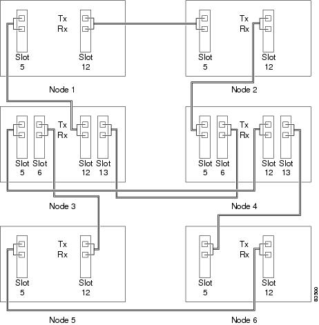
Stop. You have completed this procedure.
NTP-A46 Subtend a Path Protection from a BLSR
Purpose |
Use this procedure to subtend a path protection configuration from an existing BLSR. |
Tools/Equipment |
One BLSR node must have OC-N cards and fibers to carry the path protection configuration. |
Prerequisite Procedures |
175 Two-Fiber BLSR Acceptance Test or |
Required/As Needed |
As needed |
Onsite/Remote |
Onsite |
Security Level |
Provisioning or higher |
Step 1 ![]() In the node that will subtend the path protection configuration (Node 3 in Figure 5-8), install the two (east/west) OC-N cards that will serve as the path protection configuration trunk (span) cards (Node 3, Slots 6 and 13). See the "NTP-A16 Install the Optical Cards" procedure on page 2-13. If they are already installed, go to Step 2.
In the node that will subtend the path protection configuration (Node 3 in Figure 5-8), install the two (east/west) OC-N cards that will serve as the path protection configuration trunk (span) cards (Node 3, Slots 6 and 13). See the "NTP-A16 Install the Optical Cards" procedure on page 2-13. If they are already installed, go to Step 2.
Step 2 ![]() Attach fibers from these cards to the path protection configuration trunk cards on the neighbor path protection configuration node or nodes. In Figure 5-8, Slot 6/Node 3 connects to Slot 13/Node 4, and Slot 13/Node 3 connects to Slot 6/Node 4.
Attach fibers from these cards to the path protection configuration trunk cards on the neighbor path protection configuration node or nodes. In Figure 5-8, Slot 6/Node 3 connects to Slot 13/Node 4, and Slot 13/Node 3 connects to Slot 6/Node 4.
Step 3 ![]() Log into the ONS 15454 that will subtend the path protection configuration. See the "DLP-A60 Log into CTC" task on page 3-23 for instructions.
Log into the ONS 15454 that will subtend the path protection configuration. See the "DLP-A60 Log into CTC" task on page 3-23 for instructions.
Step 4 ![]() Complete the "DLP-A253 Provision SONET DCC Terminations" task for each OC-N card that will carry the path protection configuration.
Complete the "DLP-A253 Provision SONET DCC Terminations" task for each OC-N card that will carry the path protection configuration.
Step 5 ![]() Log into the path protection configuration node that connects to the node in Step 3.
Log into the path protection configuration node that connects to the node in Step 3.
Step 6 ![]() Complete the "DLP-A253 Provision SONET DCC Terminations" task for each OC-N card that will carry the path protection configuration.
Complete the "DLP-A253 Provision SONET DCC Terminations" task for each OC-N card that will carry the path protection configuration.
Step 7 ![]() Repeat Step 6 for each node in the path protection configuration.
Repeat Step 6 for each node in the path protection configuration.
Step 8 ![]() From the View menu, choose Go To Network View.
From the View menu, choose Go To Network View.
Figure 5-8 Path Protection Subtended from a BLSR

Step 9 ![]() Complete the "177 Path Protection Acceptance Test" procedure.
Complete the "177 Path Protection Acceptance Test" procedure.
Stop. You have completed this procedure.
NTP-A47 Subtend a BLSR from a Path Protection
Step 1 ![]() In the path protection configuration node that will subtend the BLSR, install the two (east and west) OC-N cards that will serve as the BLSR trunk (span) cards (in Figure 5-8, Node 3, Slots 5 and 12). See the "NTP-A16 Install the Optical Cards" procedure on page 2-13.
In the path protection configuration node that will subtend the BLSR, install the two (east and west) OC-N cards that will serve as the BLSR trunk (span) cards (in Figure 5-8, Node 3, Slots 5 and 12). See the "NTP-A16 Install the Optical Cards" procedure on page 2-13.
Step 2 ![]() Attach fibers from the cards in Step 1 to the BLSR trunk cards on another BLSR node or nodes. In Figure 5-8, Slot 5/Node 3 connects to Slot 12/Node 2, and Slot 12/Node 3 connects to Slot 5/Node 1.
Attach fibers from the cards in Step 1 to the BLSR trunk cards on another BLSR node or nodes. In Figure 5-8, Slot 5/Node 3 connects to Slot 12/Node 2, and Slot 12/Node 3 connects to Slot 5/Node 1.
Step 3 ![]() Log into the ONS 15454 that will subtend the BLSR (the node in Step 1). See the "DLP-A60 Log into CTC" task on page 3-23 for instructions. If you are already logged in, continue with Step 4.
Log into the ONS 15454 that will subtend the BLSR (the node in Step 1). See the "DLP-A60 Log into CTC" task on page 3-23 for instructions. If you are already logged in, continue with Step 4.
Step 4 ![]() Create the DCCs on both OC-N trunk cards (east and west) that will carry the BLSR. See the "DLP-A253 Provision SONET DCC Terminations" task for instructions.
Create the DCCs on both OC-N trunk cards (east and west) that will carry the BLSR. See the "DLP-A253 Provision SONET DCC Terminations" task for instructions.
Step 5 ![]() Create the subtending BLSR:
Create the subtending BLSR:
a. ![]() Complete the "40 Provision BLSR Nodes" procedure for each node that will be in the BLSR. If you have already provisioned the BLSR, perform this procedure for the subtending node only.
Complete the "40 Provision BLSR Nodes" procedure for each node that will be in the BLSR. If you have already provisioned the BLSR, perform this procedure for the subtending node only.
b. ![]() Complete the "126 Create a BLSR" procedure. Include the node in Step 3 (the node that will subtend the BLSR) in the BLSR.
Complete the "126 Create a BLSR" procedure. Include the node in Step 3 (the node that will subtend the BLSR) in the BLSR.
Step 6 ![]() From the View menu, choose Go to the Network View to see the subtending ring.
From the View menu, choose Go to the Network View to see the subtending ring.
Stop. You have completed this procedure.
NTP-A48 Subtend a BLSR from a BLSR
Note ![]() This procedure assumes that all nodes are configured for the BLSR. If you need to add a node to a BLSR, see the "NTP-A102 Add a BLSR Node" procedure on page 14-2.
This procedure assumes that all nodes are configured for the BLSR. If you need to add a node to a BLSR, see the "NTP-A102 Add a BLSR Node" procedure on page 14-2.
Step 1 ![]() Log into the node that will subtend the BLSR. See the "DLP-A60 Log into CTC" task on page 3-23 for instructions. If you are already logged in, continue with Step 2.
Log into the node that will subtend the BLSR. See the "DLP-A60 Log into CTC" task on page 3-23 for instructions. If you are already logged in, continue with Step 2.
Step 2 ![]() Install the OC-N cards that will serve as the BLSR trunk (span) cards if they are not already installed. See the "NTP-A16 Install the Optical Cards" procedure on page 2-13.
Install the OC-N cards that will serve as the BLSR trunk (span) cards if they are not already installed. See the "NTP-A16 Install the Optical Cards" procedure on page 2-13.
Figure 5-9 shows two BLSRs shared by one ONS 15454. Ring 1 runs on Nodes 1, 2, 3, and 4. Ring 2 runs on Nodes 4, 5, 6, and 7 and represents the subtending ring added by this procedure. Two BLSR rings, Ring 1 and Ring 2, are provisioned on Node 4. Ring 1 uses cards in Slots 5 and 12, and Ring 2 uses cards in Slots 6 and 13.
Figure 5-9 BLSR Subtended from a BLSR

Step 3 ![]() Attach fibers from the trunk cards in the subtending node to the BLSR trunk cards on its two neighboring BLSR nodes. In Figure 5-9, Node 4/Slot 6 connects to Node 7/Slot 13, and Node 4/Slot 13 connects to Node 5/Slot 6.
Attach fibers from the trunk cards in the subtending node to the BLSR trunk cards on its two neighboring BLSR nodes. In Figure 5-9, Node 4/Slot 6 connects to Node 7/Slot 13, and Node 4/Slot 13 connects to Node 5/Slot 6.
Step 4 ![]() Create the DCCs on the first OC-N card that will carry the BLSR. See the "DLP-A253 Provision SONET DCC Terminations" task for instructions.
Create the DCCs on the first OC-N card that will carry the BLSR. See the "DLP-A253 Provision SONET DCC Terminations" task for instructions.
Step 5 ![]() Repeat Step 4 for the second OC-N trunk card that will carry the BLSR.
Repeat Step 4 for the second OC-N trunk card that will carry the BLSR.
Step 6 ![]() Complete the "40 Provision BLSR Nodes" procedure for each node that will be in the BLSR. If you have already provisioned the BLSR, perform this procedure for the subtending node only.
Complete the "40 Provision BLSR Nodes" procedure for each node that will be in the BLSR. If you have already provisioned the BLSR, perform this procedure for the subtending node only.
Step 7 ![]() If the subtending BLSR is not already created, complete the "126 Create a BLSR" procedure to provision the new BLSR. The subtending BLSR must have a ring ID that differs from the ring ID of the first BLSR. The subtending node can have one Node ID that is used in both BLSRs, or a different Node ID for each BLSR. For example, the same node can be Node #4 in BLSR #1 and Node #2 in BLSR #2.
If the subtending BLSR is not already created, complete the "126 Create a BLSR" procedure to provision the new BLSR. The subtending BLSR must have a ring ID that differs from the ring ID of the first BLSR. The subtending node can have one Node ID that is used in both BLSRs, or a different Node ID for each BLSR. For example, the same node can be Node #4 in BLSR #1 and Node #2 in BLSR #2.
Step 8 ![]() Display the network view to see the subtending ring.
Display the network view to see the subtending ring.
Figure 5-10 shows an example of two subtending BLSRs.
Figure 5-10 Subtended BLSRs on the Network Map

Step 9 ![]() Complete the "175 Two-Fiber BLSR Acceptance Test" procedure or the "176 Four-Fiber BLSR Acceptance Test" procedure depending on the type of BLSR.
Complete the "175 Two-Fiber BLSR Acceptance Test" procedure or the "176 Four-Fiber BLSR Acceptance Test" procedure depending on the type of BLSR.
Stop. You have completed this procedure.
 Feedback