- About this Guide
- Chapter 1, Install the Shelf and Backplane Cable
- Chapter 2, Install Cards and Fiber-Optic Cable
- Chapter 3, Connect the PC and Log Into the GUI
- Chapter 4, Turn Up Node
- Chapter 5, Turn Up Network
- Chapter 6, Create Circuits and VT Tunnels
- Chapter 7, Manage Alarms
- Chapter 8, Monitor Performance
- Chapter 9, Manage Circuits
- Chapter 10, Change Node Settings
- Chapter 11, Change Card Settings
- Chapter 12, Upgrade Cards and Spans
- Chapter 13, Upgrade Network Configurations
- Chapter 14, Add and Remove Nodes
- Chapter 15, Maintain the Node
- Chapter 16, Power Down the ONS 15454
- Appendix A, CTC Information and Shortcuts
- Appendix B, Shelf Assembly Specifications
- Appendix C, Network Element Defaults
- Glossary
- Before You Begin
- NTP-A199 Locate and View Circuits
- NTP-A200 View Cross-Connect Card Resource Usage
- NTP-A151 Modify Circuit Characteristics
- NTP-A416 Convert a CTC Circuit to TL1 Cross-Connects
- NTP-A417 Upgrade TL1 Cross-Connects to CTC Circuits
- NTP-A152 Delete Circuits
- NTP-A78 Create a Monitor Circuit
- NTP-A79 Create a J1 Path Trace
Manage Circuits

Note ![]() The terms "Unidirectional Path Switched Ring" and "UPSR" may appear in Cisco literature. These terms do not refer to using Cisco ONS 15xxx products in a unidirectional path switched ring configuration. Rather, these terms, as well as "Path Protected Mesh Network" and "PPMN," refer generally to Cisco's path protection feature, which may be used in any topological network configuration. Cisco does not recommend using its path protection feature in any particular topological network configuration.
The terms "Unidirectional Path Switched Ring" and "UPSR" may appear in Cisco literature. These terms do not refer to using Cisco ONS 15xxx products in a unidirectional path switched ring configuration. Rather, these terms, as well as "Path Protected Mesh Network" and "PPMN," refer generally to Cisco's path protection feature, which may be used in any topological network configuration. Cisco does not recommend using its path protection feature in any particular topological network configuration.
This chapter explains how to manage Cisco ONS 15454 electrical, optical and Ethernet circuits.
Before You Begin
To create circuits, see Chapter 6, "Create Circuits and VT Tunnels."
To clear any alarm or trouble conditions, refer to the Cisco ONS 15454 Troubleshooting Guide.
This section lists the chapter procedures (NTPs). Turn to a procedure for applicable tasks (DLPs).
1. ![]() 199 Locate and View Circuits—Complete as needed.
199 Locate and View Circuits—Complete as needed.
2. ![]() 200 View Cross-Connect Card Resource Usage—Complete as needed.
200 View Cross-Connect Card Resource Usage—Complete as needed.
3. ![]() 151 Modify Circuit Characteristics—Complete as needed to edit a circuit name, change the active and standby colors of spans, or change signal fail, signal degrade thresholds, reversion time, and PDI-P settings for path protection configuration circuits.
151 Modify Circuit Characteristics—Complete as needed to edit a circuit name, change the active and standby colors of spans, or change signal fail, signal degrade thresholds, reversion time, and PDI-P settings for path protection configuration circuits.
4. ![]() 416 Convert a CTC Circuit to TL1 Cross-Connects—Complete this procedure if you want to convert a CTC circuit into TL1 cross-connects.
416 Convert a CTC Circuit to TL1 Cross-Connects—Complete this procedure if you want to convert a CTC circuit into TL1 cross-connects.
5. ![]() 417 Upgrade TL1 Cross-Connects to CTC Circuits—Complete this procedure if you want to convert TL1 cross-connects or TL1-like cross-connects created in CTC into a CTC circuit.
417 Upgrade TL1 Cross-Connects to CTC Circuits—Complete this procedure if you want to convert TL1 cross-connects or TL1-like cross-connects created in CTC into a CTC circuit.
6. ![]() 152 Delete Circuits—Complete as needed.
152 Delete Circuits—Complete as needed.
7. ![]() 78 Create a Monitor Circuit—Complete as needed to monitor traffic on primary bidirectional circuits.
78 Create a Monitor Circuit—Complete as needed to monitor traffic on primary bidirectional circuits.
8. ![]() 79 Create a J1 Path Trace—Complete as needed to monitor interruptions or changes to circuit traffic.
79 Create a J1 Path Trace—Complete as needed to monitor interruptions or changes to circuit traffic.
Figure 9-1 shows the Cisco Transport Controller Circuits window. This window displays information about circuits to help you manage the circuits, including circuit status and state.
Figure 9-1 ONS 15454 Circuit Window In Network View
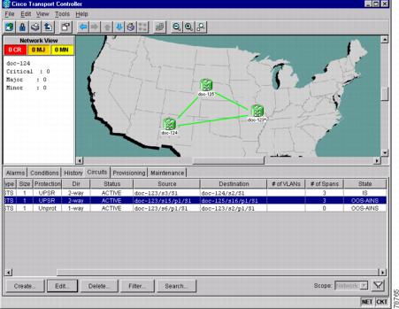
Table 9-1 lists the statuses that CTC can report for each circuit.
|
|
|
|---|---|
CREATING |
CTC is creating a circuit. |
ACTIVE |
CTC created a circuit. All components are in place and a complete path exists from the circuit source to the circuit destination. |
DELETING |
CTC is deleting a circuit. |
INCOMPLETE |
A CTC-created circuit is missing a cross-connect or network span; a complete path from source to destination(s) does not exist, or an Alarm Interface Panel (AIP) change occurred on one of the circuit nodes and the circuit is in need of repair. (AIPs store the node MAC address.) In CTC, circuits are represented using cross-connects and network spans. If a network span is missing from a circuit, the circuit status is INCOMPLETE. However, an INCOMPLETE status does not necessarily mean a circuit traffic failure has occurred, for traffic may flow on a protect path. Network spans are in one of two states: up or down. On CTC circuit and network maps, up spans are displayed as green lines, and down spans are displayed as gray lines. If a failure occurs on a network span during a CTC session, the span remains in on the network map but its color changes to gray to indicate the span is down. If you restart your CTC session while the failure is active, the new CTC session cannot discover the span and its span line will not display on the network map. Subsequently, circuits routed on a network span that goes down will display as ACTIVE during the current CTC session, but they will display as INCOMPLETE to users who log in after the span failure. |
UPGRADABLE |
A TL1-created circuit or a TL1-like CTC-created circuit is complete and has upgradable cross-connects. A complete path from source to destination(s) exists. You can upgrade the circuit using the "417 Upgrade TL1 Cross-Connects to CTC Circuits" procedure. |
INCOMPLETE_UPGRADABLE |
A TL1-created circuit or a TL1-like CTC-created circuit with upgradable cross-connects is missing a cross-connect, and a complete path from source to destination(s) does not exist. The circuit cannot be upgraded until missing cross-connects are in place. |
NOT_UPGRADABLE |
A TL1-created circuit or a TL1-like CTC-created circuit is complete but has at least one non-upgradable cross-connect. UPSR_HEAD, UPSR_EN, UPSR_DC, and UPSR_DROP cross-connects are not upgradable, so all unidirectional path protection configuration circuits created with TL1 are not upgradable. |
INCOMPLETE_NOT_UPGRADABLE |
A TL1-created circuit or a TL1-like CTC-created circuit with one or more non-upgradable cross-connects is missing a connection or circuit span (network link); a complete path from source to destination(s) does not exist. |
Circuit state, shown in Table 9-2, is a user-assigned, administrative status that defines whether the circuit is in or out of service. To carry circuit traffic, circuits must have a status of Active and a state of In Service (IS).
NTP-A199 Locate and View Circuits
Purpose |
This procedure allows you to locate and view ONS 15454 circuits. |
Tools/Equipment |
None |
Prerequisite Procedures |
Circuit creation procedure(s) in Chapter 6, "Create Circuits and VT Tunnels" |
Required/As Needed |
As needed |
Onsite/Remote |
Onsite or remote |
Security Level |
Retrieve or higher |
Step 1 ![]() Log into the network where you want to view the circuits. See the "DLP-A60 Log into CTC" task on page 3-23 for instructions. If you are already logged in, go to Step 2.
Log into the network where you want to view the circuits. See the "DLP-A60 Log into CTC" task on page 3-23 for instructions. If you are already logged in, go to Step 2.
Step 2 ![]() As needed, complete the "DLP-A131 Search for Circuits" task.
As needed, complete the "DLP-A131 Search for Circuits" task.
Step 3 ![]() As needed, complete the "DLP-A262 Filter the Display of Circuits" task.
As needed, complete the "DLP-A262 Filter the Display of Circuits" task.
Step 4 ![]() As needed, complete the "DLP-A229 View Circuits on a Span" task.
As needed, complete the "DLP-A229 View Circuits on a Span" task.
Stop. You have completed this procedure.
DLP-A131 Search for Circuits
Step 1 ![]() Navigate to the appropriate CTC view:
Navigate to the appropriate CTC view:
•![]() To search the entire network, from the View menu, choose Go to Network View.
To search the entire network, from the View menu, choose Go to Network View.
•![]() To search for circuits that originate, terminate, or pass through a specific node, from the View menu, choose Go to Other Node, then choose the node you want to search and click OK.
To search for circuits that originate, terminate, or pass through a specific node, from the View menu, choose Go to Other Node, then choose the node you want to search and click OK.
•![]() To search for circuits that originate, terminate, or pass through a specific card, double-click the card on the shelf graphic in node view to display the card in card view.
To search for circuits that originate, terminate, or pass through a specific card, double-click the card on the shelf graphic in node view to display the card in card view.
Step 2 ![]() Click the Circuits tab.
Click the Circuits tab.
Step 3 ![]() If you are in node or card view, choose the scope for the search in the Scope pull-down menu.
If you are in node or card view, choose the scope for the search in the Scope pull-down menu.
Step 4 ![]() Click Search.
Click Search.
Step 5 ![]() In the Circuit Name Search dialog box, complete the following:
In the Circuit Name Search dialog box, complete the following:
•![]() Find What—Enter the text of the circuit name you want to find.
Find What—Enter the text of the circuit name you want to find.
•![]() Match Whole Word Only—Select this check box to instruct CTC to select circuits only if the entire word matches the text in the Find What field.
Match Whole Word Only—Select this check box to instruct CTC to select circuits only if the entire word matches the text in the Find What field.
•![]() Match Case—Select this check box to instruct CTC to select circuits only when the capitalization matches the capitalization entered in the Find What field.
Match Case—Select this check box to instruct CTC to select circuits only when the capitalization matches the capitalization entered in the Find What field.
•![]() Direction—Choose the direction for the search. Searches are conducted up or down from the currently selected circuit.
Direction—Choose the direction for the search. Searches are conducted up or down from the currently selected circuit.
Step 6 ![]() Click Find Next. If a match is found, click Find Next again to find the next circuit.
Click Find Next. If a match is found, click Find Next again to find the next circuit.
Step 7 ![]() Repeat Steps 5 and 6 until you are finished, then click Cancel.
Repeat Steps 5 and 6 until you are finished, then click Cancel.
Step 8 ![]() Return to your originating procedure (NTP).
Return to your originating procedure (NTP).
DLP-A262 Filter the Display of Circuits
Step 1 ![]() Navigate to the appropriate CTC view:
Navigate to the appropriate CTC view:
•![]() To filter network circuits, from the View menu, choose Go to Network View.
To filter network circuits, from the View menu, choose Go to Network View.
•![]() To filter circuits that originate, terminate, or pass through a specific node, from the View menu, choose Go to Other Node, then choose the node you want to search and click OK.
To filter circuits that originate, terminate, or pass through a specific node, from the View menu, choose Go to Other Node, then choose the node you want to search and click OK.
•![]() To filter circuits that originate, terminate, or pass through a specific card, double-click the card on the shelf graphic in node view to display the card in card view.
To filter circuits that originate, terminate, or pass through a specific card, double-click the card on the shelf graphic in node view to display the card in card view.
Step 2 ![]() Click the Circuits tab.
Click the Circuits tab.
Step 3 ![]() Set the attributes for filtering the circuit display:
Set the attributes for filtering the circuit display:
a. ![]() Click the Filter button.
Click the Filter button.
b. ![]() On the Filter Dialog, set the filter attributes:
On the Filter Dialog, set the filter attributes:
•![]() Name—Enter a complete or partial circuit name to filter circuits based on circuit name; otherwise leave the field blank.
Name—Enter a complete or partial circuit name to filter circuits based on circuit name; otherwise leave the field blank.
•![]() Direction—Choose one: Any (direction not used to filter circuits), 1-way (display only one-way circuits), or 2-way (display only two-way circuits).
Direction—Choose one: Any (direction not used to filter circuits), 1-way (display only one-way circuits), or 2-way (display only two-way circuits).
•![]() Status—Choose one: Any (status not used to filter circuits), Active (display only active circuits), Incomplete (display only incomplete circuits, that is, circuits missing a connection or span to form a complete path), or Upgradable (display only upgradable circuits, that is, circuits created in TL1 that are ready to upgrade in CTC). See Table 9-1 for more information about circuit statuses. (While other statuses are described in the table, filtering is only supported for Active, Incomplete, and Upgradable circuits.)
Status—Choose one: Any (status not used to filter circuits), Active (display only active circuits), Incomplete (display only incomplete circuits, that is, circuits missing a connection or span to form a complete path), or Upgradable (display only upgradable circuits, that is, circuits created in TL1 that are ready to upgrade in CTC). See Table 9-1 for more information about circuit statuses. (While other statuses are described in the table, filtering is only supported for Active, Incomplete, and Upgradable circuits.)
•![]() State—Choose one: OOS (display only out of service circuits), IS (display only inservice circuits), OOS-AINS (display only out of service, auto inservice circuits), or OOS-MT (display only out of service, maintenance circuits.) See Table 9-2 for more information about circuit states.
State—Choose one: OOS (display only out of service circuits), IS (display only inservice circuits), OOS-AINS (display only out of service, auto inservice circuits), or OOS-MT (display only out of service, maintenance circuits.) See Table 9-2 for more information about circuit states.
•![]() Slot—Enter a slot number to filter circuits based on the source or destination slot; otherwise leave the field blank.
Slot—Enter a slot number to filter circuits based on the source or destination slot; otherwise leave the field blank.
•![]() Port—Enter a port number to filter circuits based on the source or destination port; otherwise leave the field blank.
Port—Enter a port number to filter circuits based on the source or destination port; otherwise leave the field blank.
•![]() Type—Choose one: Any (type not used to filter circuits), STS (displays only STS circuits), VT (displays only VT circuits), VT Tunnel (displays only VT tunnels), or VT Aggregation Point (displays only VT aggregation points).
Type—Choose one: Any (type not used to filter circuits), STS (displays only STS circuits), VT (displays only VT circuits), VT Tunnel (displays only VT tunnels), or VT Aggregation Point (displays only VT aggregation points).
•![]() Size—Click the appropriate check boxes to filter circuits based on size: VT1.5, STS-1, STS3c, STS-6c, STS-9c, STS-12c, STS-24c, STS-48c, or STS-192c. The check boxes displayed depend on what you entered in the Type field. If you chose Any, all sizes are available. If you chose VT, only VT1.5 is available. If you chose STS, only STS sizes are available, and if you chose VT Tunnel or VT Aggregation Point, only STS-1 is available.
Size—Click the appropriate check boxes to filter circuits based on size: VT1.5, STS-1, STS3c, STS-6c, STS-9c, STS-12c, STS-24c, STS-48c, or STS-192c. The check boxes displayed depend on what you entered in the Type field. If you chose Any, all sizes are available. If you chose VT, only VT1.5 is available. If you chose STS, only STS sizes are available, and if you chose VT Tunnel or VT Aggregation Point, only STS-1 is available.
Step 4 ![]() Click OK. Circuits matching the attributes in the Filter Circuits dialog box are displayed in the Circuits window.
Click OK. Circuits matching the attributes in the Filter Circuits dialog box are displayed in the Circuits window.
Step 5 ![]() To turn filtering off, click the Filter icon in the lower right corner of the Circuits window. Click the icon again to turn filtering on, and click the Filter button to change the filter attributes.
To turn filtering off, click the Filter icon in the lower right corner of the Circuits window. Click the icon again to turn filtering on, and click the Filter button to change the filter attributes.
Step 6 ![]() Return to your originating procedure (NTP).
Return to your originating procedure (NTP).
DLP-A229 View Circuits on a Span
Purpose |
This task allows you to view circuits on an ONS 15454 span. |
Tools/Equipment |
None |
Prerequisite Procedures |
Circuits must be created on the span. See Chapter 6, "Create Circuits and VT Tunnels" |
Required/As Needed |
As needed |
Onsite/Remote |
Onsite or remote |
Security Level |
Retrieve or higher |
Step 1 ![]() From the View menu on the node view, choose Go to Network View. If you are already in network view, go to Step 2.
From the View menu on the node view, choose Go to Network View. If you are already in network view, go to Step 2.
Step 2 ![]() Right-click the green line containing the circuits you want to view and choose one of the following:
Right-click the green line containing the circuits you want to view and choose one of the following:
•![]() Circuits—To view BLSR, path protection configuration, 1+1, or unprotected circuits on the span.
Circuits—To view BLSR, path protection configuration, 1+1, or unprotected circuits on the span.
•![]() PCA Circuits—To view circuits routed on a BLSR protected channel. (This option does not display if the span you right-clicked is not a BLSR span.)
PCA Circuits—To view circuits routed on a BLSR protected channel. (This option does not display if the span you right-clicked is not a BLSR span.)
On the Circuits on Span dialog box, you can view the following information for circuits provisioned on the span:
•![]() STS—STSs used by the circuits.
STS—STSs used by the circuits.
•![]() VT—VTs used by the circuits (VT circuits).
VT—VTs used by the circuits (VT circuits).
•![]() UPSR—(UPSR span only)—If checked, path protection configuration circuits are on the span.
UPSR—(UPSR span only)—If checked, path protection configuration circuits are on the span.
•![]() Circuit—Displays the circuit name.
Circuit—Displays the circuit name.
•![]() Switch State—(UPSR span only) Displays the switch state of the circuit, that is, whether any span switches are active. For path protection configuration spans, switch types include: CLEAR (no spans are switched), MANUAL (a manual switch is active), FORCE (a force switch is active), and LOCKOUT OF PROTECTION (a span lockout is active).
Switch State—(UPSR span only) Displays the switch state of the circuit, that is, whether any span switches are active. For path protection configuration spans, switch types include: CLEAR (no spans are switched), MANUAL (a manual switch is active), FORCE (a force switch is active), and LOCKOUT OF PROTECTION (a span lockout is active).
Note ![]() You can perform other procedures from the Circuits on Span dialog box. If the span is in a path protection configuration, you can switch the span traffic. See "DLP-A197 Initiate a Path Protection Configuration Force Switch" task on page 14-18 for instructions. If you want to edit a circuit on the span, double-click the circuit. See the "DLP-A231 Edit a Circuit Name" task or the "DLP-A233 Edit Path Protection configuration Circuit Path Selectors" task for instructions.
You can perform other procedures from the Circuits on Span dialog box. If the span is in a path protection configuration, you can switch the span traffic. See "DLP-A197 Initiate a Path Protection Configuration Force Switch" task on page 14-18 for instructions. If you want to edit a circuit on the span, double-click the circuit. See the "DLP-A231 Edit a Circuit Name" task or the "DLP-A233 Edit Path Protection configuration Circuit Path Selectors" task for instructions.
Step 3 ![]() Return to your originating procedure (NTP).
Return to your originating procedure (NTP).
NTP-A200 View Cross-Connect Card Resource Usage
Step 1 ![]() Log into the node where you want to view the cross-connect card resource usage. See the "DLP-A60 Log into CTC" task on page 3-23 for instructions. If you are already logged in, go to Step 2.
Log into the node where you want to view the cross-connect card resource usage. See the "DLP-A60 Log into CTC" task on page 3-23 for instructions. If you are already logged in, go to Step 2.
Step 2 ![]() Click the Maintenance > Cross-Connect > Resource Usage tabs.
Click the Maintenance > Cross-Connect > Resource Usage tabs.
Step 3 ![]() In the Summary section of the Resources Usage tab, view the following information:
In the Summary section of the Resources Usage tab, view the following information:
•![]() STS-1 Paths—(XC, XCVT, XC10G) Provides the percent of the cross-connect card STS-1path resources that are used. 288 STS-1 paths are available for XC or XCVT cards; 1152 STS-1 paths are available for XC10G cards.
STS-1 Paths—(XC, XCVT, XC10G) Provides the percent of the cross-connect card STS-1path resources that are used. 288 STS-1 paths are available for XC or XCVT cards; 1152 STS-1 paths are available for XC10G cards.
•![]() VT Matrix Ports—(XCVT and XC10G) Provides the percent of the cross-connect card VT matrix ports that are used. Each port is one STS in size, and each can transport 28 VT1.5s. 24 VT matrix ports are available for the XCVT and XV10G cards.
VT Matrix Ports—(XCVT and XC10G) Provides the percent of the cross-connect card VT matrix ports that are used. Each port is one STS in size, and each can transport 28 VT1.5s. 24 VT matrix ports are available for the XCVT and XV10G cards.
•![]() VT Matrix—(XCVT and XC10G) Provides the percent of the VT matrix resources that are used. 672 are available, which is the number of VT matrix ports (24) multiplied by the number of VT1.5s in an STS (28).
VT Matrix—(XCVT and XC10G) Provides the percent of the VT matrix resources that are used. 672 are available, which is the number of VT matrix ports (24) multiplied by the number of VT1.5s in an STS (28).
Step 4 ![]() In the VT Port Matrix Detail section, you can view details of the VT Matrix Port usage:
In the VT Port Matrix Detail section, you can view details of the VT Matrix Port usage:
•![]() Drop—Identifies the source slot, port, and STS.
Drop—Identifies the source slot, port, and STS.
•![]() Tunnel Name—VT tunnels use VT matrix ports on the tunnel source and destination nodes (VT tunnels do not use matrix resources on pass-through nodes). If the port is used by a VT tunnel, the tunnel name will appear here.
Tunnel Name—VT tunnels use VT matrix ports on the tunnel source and destination nodes (VT tunnels do not use matrix resources on pass-through nodes). If the port is used by a VT tunnel, the tunnel name will appear here.
•![]() % Uses—Shows the percent of the matrix port that is used. Each matrix port can carry 28 VT1.5s, so for example, if one STS carries seven VT1.5 circuits, the matrix port will be 25% used.
% Uses—Shows the percent of the matrix port that is used. Each matrix port can carry 28 VT1.5s, so for example, if one STS carries seven VT1.5 circuits, the matrix port will be 25% used.
•![]() Usage—Shows the port usage. For example, if one STS carries seven VT1.5 circuits, the matrix port will show that 7 of 28 are used.
Usage—Shows the port usage. For example, if one STS carries seven VT1.5 circuits, the matrix port will show that 7 of 28 are used.
Stop. You have completed this procedure.
NTP-A151 Modify Circuit Characteristics
Purpose |
This procedure provides tasks that you can use to edit or change the properties of ONS 15454 circuits. |
Tools/Equipment |
None |
Prerequisite Procedures |
Circuits must exist on the network. See Chapter 6, "Create Circuits and VT Tunnels" for circuit creation procedures. |
Required/As Needed |
As needed |
Onsite/Remote |
Onsite or remote |
Security Level |
Provisioning or higher |
Step 1 ![]() Log into the network containing the circuit you want to modify. See the "DLP-A60 Log into CTC" task on page 3-23 for instructions. If you are already logged in, go to Step 2.
Log into the network containing the circuit you want to modify. See the "DLP-A60 Log into CTC" task on page 3-23 for instructions. If you are already logged in, go to Step 2.
Step 2 ![]() As needed, complete the "DLP-A231 Edit a Circuit Name" task.
As needed, complete the "DLP-A231 Edit a Circuit Name" task.
Step 3 ![]() As needed, complete the "DLP-A232 Change Active and Standby Span Color" task.
As needed, complete the "DLP-A232 Change Active and Standby Span Color" task.
Step 4 ![]() As needed, complete the "DLP-A233 Edit Path Protection configuration Circuit Path Selectors" task.
As needed, complete the "DLP-A233 Edit Path Protection configuration Circuit Path Selectors" task.
Stop. You have completed this procedure.
DLP-A230 Change a Circuit State
Purpose |
This task changes the state of a circuit. |
Tools/Equipment |
None |
Prerequisite Procedures |
|
Required/As Needed |
As needed |
Onsite/Remote |
Onsite or remote |
Security Level |
Provisioning or higher |
Step 1 ![]() Click the Circuits tab.
Click the Circuits tab.
Step 2 ![]() Click the circuit with the state you want to change.
Click the circuit with the state you want to change.
Note ![]() You cannot edit the circuit state if the circuit is routed to nodes with a CTC software release older than Release 3.4. These circuits will automatically be in service (IS).
You cannot edit the circuit state if the circuit is routed to nodes with a CTC software release older than Release 3.4. These circuits will automatically be in service (IS).
Step 3 ![]() From the Tools menu, choose Circuits > Set Circuit State.
From the Tools menu, choose Circuits > Set Circuit State.
Note ![]() Alternatively, you can click the Edit button, then click the State tab on the Edit Circuits window.
Alternatively, you can click the Edit button, then click the State tab on the Edit Circuits window.
Step 4 ![]() On the Set Circuit State dialog box (Figure 9-2) change the circuit state by choosing one of the following choices from the Target Circuit State pull-down menu:
On the Set Circuit State dialog box (Figure 9-2) change the circuit state by choosing one of the following choices from the Target Circuit State pull-down menu:
•![]() IS—Places the circuit in service
IS—Places the circuit in service
•![]() OOS—Places the circuit out of service
OOS—Places the circuit out of service
•![]() OOS-AINS—Places the circuit out of service, auto in service
OOS-AINS—Places the circuit out of service, auto in service
•![]() OOS-MT—Places the circuit out of service, maintenance
OOS-MT—Places the circuit out of service, maintenance
See Table 9-2 for additional information about circuit states.
Step 5 ![]() If you want to apply the state to the circuit source and destination ports, check the Apply to Drop Ports check box.
If you want to apply the state to the circuit source and destination ports, check the Apply to Drop Ports check box.
Figure 9-2 Changing Circuit State

Step 6 ![]() Click OK.
Click OK.
Note ![]() CTC will not change the state of the circuit source and destination port in certain circumstances. For example, if the circuit size is smaller than the port, for example, a VT1.5 circuit on an STS port, CTC will not change the port state from IS to OOS. If CTC cannot change the port state, a message is displayed and you must change the port state manually.
CTC will not change the state of the circuit source and destination port in certain circumstances. For example, if the circuit size is smaller than the port, for example, a VT1.5 circuit on an STS port, CTC will not change the port state from IS to OOS. If CTC cannot change the port state, a message is displayed and you must change the port state manually.
Step 7 ![]() Return to your originating procedure (NTP).
Return to your originating procedure (NTP).
DLP-A231 Edit a Circuit Name
Purpose |
This task edits a circuit name. |
Tools/Equipment |
None |
Prerequisite Procedures |
|
Required/As Needed |
As needed |
Onsite/Remote |
Onsite or remote |
Security Level |
Provisioning or higher |
Step 1 ![]() Click the Circuits tab.
Click the Circuits tab.
Step 2 ![]() Click the circuit you want to rename, then click Edit.
Click the circuit you want to rename, then click Edit.
Step 3 ![]() On the General tab, click the Name field and edit or rename the circuit. Names can be up to 48 alphanumeric and/or special characters. However, if you will ever create a monitor circuit on this circuit, do not make the name longer than 44 characters because monitor circuits will add "_MON" (four characters) to the circuit name.
On the General tab, click the Name field and edit or rename the circuit. Names can be up to 48 alphanumeric and/or special characters. However, if you will ever create a monitor circuit on this circuit, do not make the name longer than 44 characters because monitor circuits will add "_MON" (four characters) to the circuit name.
Step 4 ![]() Click the Apply button.
Click the Apply button.
Step 5 ![]() From File menu, select Close.
From File menu, select Close.
Step 6 ![]() On the Circuits window, verify that the circuit was correctly renamed.
On the Circuits window, verify that the circuit was correctly renamed.
Step 7 ![]() Return to your originating procedure (NTP).
Return to your originating procedure (NTP).
DLP-A232 Change Active and Standby Span Color
Step 1 ![]() From the Edit menu, choose Preferences.
From the Edit menu, choose Preferences.
Step 2 ![]() On the Preferences dialog box, click the Circuit tab.
On the Preferences dialog box, click the Circuit tab.
Step 3 ![]() Complete one or more of the following steps, as required:
Complete one or more of the following steps, as required:
•![]() To change the color of the active (working) span, go to Step 4.
To change the color of the active (working) span, go to Step 4.
•![]() To change the color of the standby (protect) span, go to Step 5.
To change the color of the standby (protect) span, go to Step 5.
•![]() To return active and standby spans to their default colors, go to Step 6.
To return active and standby spans to their default colors, go to Step 6.
Step 4 ![]() Change the color of the active span:
Change the color of the active span:
a. ![]() Next to Active Span Color, click the Color button.
Next to Active Span Color, click the Color button.
b. ![]() On the Pick a Color dialog box, click the color for the active span, or click the Reset button if you want the active span to display the last applied (saved) color.
On the Pick a Color dialog box, click the color for the active span, or click the Reset button if you want the active span to display the last applied (saved) color.
c. ![]() Click OK to close the Pick a Color dialog box. If you want to change the standby span color, go to Step 5. If not, click OK to save the change and close the Preferences dialog box, or click Apply to save the change and keep the Preferences dialog box displayed.
Click OK to close the Pick a Color dialog box. If you want to change the standby span color, go to Step 5. If not, click OK to save the change and close the Preferences dialog box, or click Apply to save the change and keep the Preferences dialog box displayed.
Step 5 ![]() Change the color of the standby span:
Change the color of the standby span:
a. ![]() Next to Standby Span Color, click the Color button.
Next to Standby Span Color, click the Color button.
b. ![]() On the Pick a Color dialog box, click the color for the standby span, or click the Reset button if you want the standby span to display the last applied (saved) color.
On the Pick a Color dialog box, click the color for the standby span, or click the Reset button if you want the standby span to display the last applied (saved) color.
c. ![]() Click OK to save the change and close the Preferences dialog box, or click Apply to save the change and keep the Preferences dialog box displayed.
Click OK to save the change and close the Preferences dialog box, or click Apply to save the change and keep the Preferences dialog box displayed.
Step 6 ![]() Return the active and standby spans to their default colors:
Return the active and standby spans to their default colors:
a. ![]() From the Edit menu, choose Preferences.
From the Edit menu, choose Preferences.
b. ![]() On the Preferences dialog box, click the Circuits tab.
On the Preferences dialog box, click the Circuits tab.
c. ![]() Click the Reset to Defaults button.
Click the Reset to Defaults button.
d. ![]() Click OK to save the change and close the Preferences dialog box, or click Apply to save the change and keep the Preferences dialog box displayed.
Click OK to save the change and close the Preferences dialog box, or click Apply to save the change and keep the Preferences dialog box displayed.
Step 7 ![]() Return to your originating procedure (NTP).
Return to your originating procedure (NTP).
DLP-A233 Edit Path Protection configuration Circuit Path Selectors
Purpose |
This task changes the path protection configuration signal fail and signal degrade thresholds, the reversion and reversion time, and the PDI-P settings for one or more path protection configuration circuits. |
Tools/Equipment |
None |
Prerequisite Procedures |
NTP-A44 Provision Path Protection Nodes, page 5-32 |
Required/As Needed |
As needed |
Onsite/Remote |
Onsite or remote |
Security Level |
Provisioning or higher |
Step 1 ![]() Click the Circuits tab.
Click the Circuits tab.
Step 2 ![]() On the Circuits tab, click the path protection configuration circuit(s) you want to edit. To change the settings for multiple circuits, press the Shift key (to choose adjoining circuits) or the Ctrl key (to choose non-adjoining circuits) and click each circuit you want to change.
On the Circuits tab, click the path protection configuration circuit(s) you want to edit. To change the settings for multiple circuits, press the Shift key (to choose adjoining circuits) or the Ctrl key (to choose non-adjoining circuits) and click each circuit you want to change.
Step 3 ![]() From the Tools menu, choose Circuits > Set Path Selector Attributes.
From the Tools menu, choose Circuits > Set Path Selector Attributes.
Note ![]() Alternatively, for single circuits, you can click the Edit button, then click the UPSR Selectors tab on the Edit Circuits window.
Alternatively, for single circuits, you can click the Edit button, then click the UPSR Selectors tab on the Edit Circuits window.
Step 4 ![]() On the Path Selectors Attributes dialog box (Figure 9-3), edit the following path protection configuration selectors, as needed:
On the Path Selectors Attributes dialog box (Figure 9-3), edit the following path protection configuration selectors, as needed:
•![]() Revertive—If checked, traffic reverts to the working path when conditions that diverted it to the protect path are repaired. If not checked, traffic does not revert.
Revertive—If checked, traffic reverts to the working path when conditions that diverted it to the protect path are repaired. If not checked, traffic does not revert.
•![]() Reversion Time (Min)—If Revertive is checked, sets the amount of time that will elapse before traffic reverts to the working path. The range is 0.5 to 12 minutes in 0.5 minute increments.
Reversion Time (Min)—If Revertive is checked, sets the amount of time that will elapse before traffic reverts to the working path. The range is 0.5 to 12 minutes in 0.5 minute increments.
•![]() SF Ber Level—Sets the path protection configuration signal failure BER threshold (STS circuits only).
SF Ber Level—Sets the path protection configuration signal failure BER threshold (STS circuits only).
•![]() SD Ber Level—Sets the path protection configuration signal degrade BER threshold (STS circuits only).
SD Ber Level—Sets the path protection configuration signal degrade BER threshold (STS circuits only).
•![]() PDI-P—When checked, traffic switches if an STS payload defect indication is received (STS circuits only).
PDI-P—When checked, traffic switches if an STS payload defect indication is received (STS circuits only).
Step 5 ![]() Click OK and verify that the changed values are correct.
Click OK and verify that the changed values are correct.
Figure 9-3 Editing Path Protection configuration Path Selectors

Step 6 ![]() Return to your originating procedure (NTP).
Return to your originating procedure (NTP).
DLP-A263 Edit Path Protection configuration Dual Ring Interconnect Circuit Hold-Off Timer
Purpose |
This task changes the amount of time a path selector switch is delayed for circuits routed on path protection configuration dual ring interconnect (DRI) topology. In DRIs, switching contention might occur depending upon the relative switching speed of the path selector and the transmission delay on the alternative routes. The hold-off time (HOT) allows you to change switch times to prevent the switching contention. |
Tools/Equipment |
None |
Prerequisite Procedures |
NTP-A44 Provision Path Protection Nodes, page 5-32 |
Required/As Needed |
As needed |
Onsite/Remote |
Onsite or remote |
Security Level |
Provisioning or higher |
Note ![]() Cisco recommends that you set the DRI port HOT value to zero and the circuit path selector HOT value to a number equal to or greater than zero.
Cisco recommends that you set the DRI port HOT value to zero and the circuit path selector HOT value to a number equal to or greater than zero.
Step 1 ![]() Click the Circuits tab.
Click the Circuits tab.
Step 2 ![]() Click the path protection configuration circuit you want to edit, then click the Edit button.
Click the path protection configuration circuit you want to edit, then click the Edit button.
Step 3 ![]() On the Edit Circuit window, click the UPSR Selectors tab.
On the Edit Circuit window, click the UPSR Selectors tab.
Step 4 ![]() Create a hold-off time for the circuit source and destination ports:
Create a hold-off time for the circuit source and destination ports:
a. ![]() Under Holder Off Timer, double-click the cell of the circuit source port (top row), then type the new hold-off time. The range is 0 to 10,000 ms in increments of 100.
Under Holder Off Timer, double-click the cell of the circuit source port (top row), then type the new hold-off time. The range is 0 to 10,000 ms in increments of 100.
b. ![]() Under Hold-Off Timer, double-click the cell of the circuit destination port (bottom row), then type the hold-off time entered in Step a.
Under Hold-Off Timer, double-click the cell of the circuit destination port (bottom row), then type the hold-off time entered in Step a.
Step 5 ![]() Click Apply, then close the Edit Circuit window by choosing Close from the File menu.
Click Apply, then close the Edit Circuit window by choosing Close from the File menu.
Step 6 ![]() Return to your originating procedure (NTP).
Return to your originating procedure (NTP).
NTP-A416 Convert a CTC Circuit to TL1 Cross-Connects
Note ![]() You can only use this procedure with DS-1, DS-3, or OC-N circuits. You cannot use the procedure with Ethernet circuits, VT tunnels, or VT aggregation points.
You can only use this procedure with DS-1, DS-3, or OC-N circuits. You cannot use the procedure with Ethernet circuits, VT tunnels, or VT aggregation points.
Step 1 ![]() Log into an ONS 15454 node on the network where you want to convert the CTC circuits. See the "DLP-A60 Log into CTC" task on page 3-23 for instructions. If you are already logged in, go to Step 2.
Log into an ONS 15454 node on the network where you want to convert the CTC circuits. See the "DLP-A60 Log into CTC" task on page 3-23 for instructions. If you are already logged in, go to Step 2.
Step 2 ![]() From the View menu, choose Go to Network View.
From the View menu, choose Go to Network View.
Step 3 ![]() Click the Circuits tab, then choose the CTC circuit(s) that you want to convert to TL1 cross-connects. The circuit(s) must have an INCOMPLETE or ACTIVE status.
Click the Circuits tab, then choose the CTC circuit(s) that you want to convert to TL1 cross-connects. The circuit(s) must have an INCOMPLETE or ACTIVE status.
Step 4 ![]() From the Tools menu, choose Circuits > Convert CTC Circuit to TL1 Cross-Connects.
From the Tools menu, choose Circuits > Convert CTC Circuit to TL1 Cross-Connects.
Step 5 ![]() On the Convert to TL1 Cross Connect dialog box, click OK.
On the Convert to TL1 Cross Connect dialog box, click OK.
The Convert to TL1 Cross Connect Results dialog box displays the results of the conversion. If any circuits could not be converted, those circuits are listed.
Step 6 ![]() On the Convert to TL1 Cross Connect Results dialog box, click OK.
On the Convert to TL1 Cross Connect Results dialog box, click OK.
If the circuit you selected had an INCOMPLETE status, its status will not change. If you selected an ACTIVE (complete) circuit, its status will change to UPGRADABLE.
Step 7 ![]() If you are repairing a circuit, complete the circuit creation procedure in Chapter 6, "Create Circuits and VT Tunnels," appropriate to the circuit you are repairing to replace or repair the circuit cross-connects. On the Circuit Creation wizard, shown in Figure 9-4, check Create cross-connects only (TL1-like).
If you are repairing a circuit, complete the circuit creation procedure in Chapter 6, "Create Circuits and VT Tunnels," appropriate to the circuit you are repairing to replace or repair the circuit cross-connects. On the Circuit Creation wizard, shown in Figure 9-4, check Create cross-connects only (TL1-like).
After you repair or replace all missing cross-connects, CTC automatically merges them and the circuit status changes to UPGRADABLE.
Figure 9-4 Choosing the Cross-Connects Only Option

Step 8 ![]() To upgrade the repaired circuit to a CTC circuit, go to the "417 Upgrade TL1 Cross-Connects to CTC Circuits" procedure.
To upgrade the repaired circuit to a CTC circuit, go to the "417 Upgrade TL1 Cross-Connects to CTC Circuits" procedure.
Stop. You have completed this procedure.
NTP-A417 Upgrade TL1 Cross-Connects to CTC Circuits
Step 1 ![]() Log into an ONS 15454 node on the network where you want to upgrade the TL1-created or CTC-created TL1-like cross-connects. See the "DLP-A60 Log into CTC" task on page 3-23 for instructions. If you are already logged in, go to Step 2.
Log into an ONS 15454 node on the network where you want to upgrade the TL1-created or CTC-created TL1-like cross-connects. See the "DLP-A60 Log into CTC" task on page 3-23 for instructions. If you are already logged in, go to Step 2.
Step 2 ![]() From the View menu, choose Go to Network View.
From the View menu, choose Go to Network View.
Step 3 ![]() Click the Circuits tab, then choose one or more circuits with an UPGRADABLE status. These circuits contain a series of cross-connects that are linked together to form a circuit path. The cross-connects may have been created with TL1 or with CTC using the TL1-like cross-connects option.
Click the Circuits tab, then choose one or more circuits with an UPGRADABLE status. These circuits contain a series of cross-connects that are linked together to form a circuit path. The cross-connects may have been created with TL1 or with CTC using the TL1-like cross-connects option.
Step 4 ![]() From the Tools menu, choose Circuits > Upgrade TL1 Cross-Connects to CTC Circuits.
From the Tools menu, choose Circuits > Upgrade TL1 Cross-Connects to CTC Circuits.
Step 5 ![]() On the Upgrade Circuits dialog box, click OK.
On the Upgrade Circuits dialog box, click OK.
The circuit status changes to ACTIVE.
Step 6 ![]() On the Circuit Upgrade Results dialog box, click OK.
On the Circuit Upgrade Results dialog box, click OK.
Stop. You have completed this procedure.
NTP-A152 Delete Circuits
Purpose |
This procedure deletes circuits. |
Tools/Equipment |
None |
Prerequisite Procedures |
Circuits must exist on the network. See Chapter 6, "Create Circuits and VT Tunnels" for circuit creation procedures. |
Required/As Needed |
As needed |
Onsite/Remote |
Onsite or remote |
Security Level |
Provisioning or higher |
Step 1 ![]() Log into an ONS 15454 node on the network where you want to delete the circuit. See the DLP-A60 Log into CTC, page 3-23 for instructions. If you are already logged in, go to Step 2.
Log into an ONS 15454 node on the network where you want to delete the circuit. See the DLP-A60 Log into CTC, page 3-23 for instructions. If you are already logged in, go to Step 2.
Step 2 ![]() Complete the "NTP-A108 Back Up the Database" procedure on page 15-8.
Complete the "NTP-A108 Back Up the Database" procedure on page 15-8.
Step 3 ![]() Investigate all network alarms and resolve any problems that may be affected by the circuit deletion. Refer to the Alarm Troubleshooting chapter in the Cisco ONS 15454 Troubleshooting Guide.
Investigate all network alarms and resolve any problems that may be affected by the circuit deletion. Refer to the Alarm Troubleshooting chapter in the Cisco ONS 15454 Troubleshooting Guide.
Step 4 ![]() Verify that traffic is no longer carried on the circuit and that the circuit can be safely deleted.
Verify that traffic is no longer carried on the circuit and that the circuit can be safely deleted.
Step 5 ![]() Click the Circuits tab.
Click the Circuits tab.
Step 6 ![]() Choose the circuit(s) you want to delete, then click Delete.
Choose the circuit(s) you want to delete, then click Delete.
Step 7 ![]() On the Delete Circuits confirmation dialog box, check Set drop ports to OOS if you want to put the circuit source and destination ports out of service. (CTC will place the ports out of service only if the circuit is the same size as the port or is the only circuit using the port.) Click Yes to confirm the deletion.
On the Delete Circuits confirmation dialog box, check Set drop ports to OOS if you want to put the circuit source and destination ports out of service. (CTC will place the ports out of service only if the circuit is the same size as the port or is the only circuit using the port.) Click Yes to confirm the deletion.
Step 8 ![]() Complete the "NTP-A108 Back Up the Database" procedure on page 15-8.
Complete the "NTP-A108 Back Up the Database" procedure on page 15-8.
Stop. You have completed this procedure.
NTP-A78 Create a Monitor Circuit
Purpose |
This procedure creates a monitor circuit that monitors traffic on primary, bidirectional circuits. |
Tools/Equipment |
None |
Prerequisite Procedures |
Bidirectional (2-way) circuits must exist on the network. See Chapter 6, "Create Circuits and VT Tunnels" for circuit creation procedures. |
Required/As Needed |
As needed |
Onsite/Remote |
Onsite or remote |
Security Level |
Provisioning or higher |
Note ![]() Monitor circuits cannot be used with EtherSwitch circuits.
Monitor circuits cannot be used with EtherSwitch circuits.
Note ![]() For unidirectional circuits, create a drop to the port where the test equipment is attached.
For unidirectional circuits, create a drop to the port where the test equipment is attached.
Step 1 ![]() Log into an ONS 15454 node on the network where you will create the monitor circuit. See the "DLP-A60 Log into CTC" task on page 3-23 for instructions. If you are already logged in, go to Step 2.
Log into an ONS 15454 node on the network where you will create the monitor circuit. See the "DLP-A60 Log into CTC" task on page 3-23 for instructions. If you are already logged in, go to Step 2.
Step 2 ![]() From the View menu, choose Go to Network View.
From the View menu, choose Go to Network View.
Step 3 ![]() Click the Circuits tab.
Click the Circuits tab.
Step 4 ![]() Choose the bidirectional (2-way) circuit that you want to monitor and double-click it (or click Edit).
Choose the bidirectional (2-way) circuit that you want to monitor and double-click it (or click Edit).
Step 5 ![]() Verify that the circuit name is no more than 44 characters. Monitor circuits append a "_MON" to the circuit name. If the name is longer than 44 characters, edit the name in the Name field, then click Apply.
Verify that the circuit name is no more than 44 characters. Monitor circuits append a "_MON" to the circuit name. If the name is longer than 44 characters, edit the name in the Name field, then click Apply.
Step 6 ![]() On the Edit Circuit window, click the Monitors tab.
On the Edit Circuit window, click the Monitors tab.
The Monitors tab displays ports that you can use to monitor the circuit.
Note ![]() The Monitor tab is only available when the circuit has an ACTIVE status.
The Monitor tab is only available when the circuit has an ACTIVE status.
Step 7 ![]() On the Monitors tab, choose the monitor source port. The monitor circuit will display traffic coming into the node at the port you choose.
On the Monitors tab, choose the monitor source port. The monitor circuit will display traffic coming into the node at the port you choose.
Note ![]() In Figure 9-5, you would choose either the DS1-14 card (to test circuit traffic entering Node 2 on the DS1-14) or the OC-N card at Node 1 (to test circuit traffic entering Node 1 on the OC-N card).
In Figure 9-5, you would choose either the DS1-14 card (to test circuit traffic entering Node 2 on the DS1-14) or the OC-N card at Node 1 (to test circuit traffic entering Node 1 on the OC-N card).
Step 8 ![]() Click Create Monitor Circuit.
Click Create Monitor Circuit.
Step 9 ![]() In the Circuit Destination section of the Circuit Creation wizard, choose the destination node, slot, port, STS, VT, or DS1 for the monitored circuit.
In the Circuit Destination section of the Circuit Creation wizard, choose the destination node, slot, port, STS, VT, or DS1 for the monitored circuit.
Note ![]() In the Figure 9-5 example, the monitor circuit destination is Port 2 on the EC1-12 card.
In the Figure 9-5 example, the monitor circuit destination is Port 2 on the EC1-12 card.
Step 10 ![]() Click Next.
Click Next.
Step 11 ![]() On the Circuit Routing Preferences panel, review the monitor circuit information. If you want the monitor circuit routed on a BLSR protection channel, click Protection Channel Access.
On the Circuit Routing Preferences panel, review the monitor circuit information. If you want the monitor circuit routed on a BLSR protection channel, click Protection Channel Access.
Step 12 ![]() Click Finish.
Click Finish.
Step 13 ![]() On the Edit Circuit window, click Close. The new monitor circuit appears on the Circuits tab.
On the Edit Circuit window, click Close. The new monitor circuit appears on the Circuits tab.
Figure 9-5 shows a sample monitor circuit setup. VT1.5 traffic is received by Port 1 of the EC1-12 card at Node 1. To monitor the VT1.5 traffic, test equipment is plugged into Port 2 of the EC1-12 card and a monitor circuit to Port 2 is provisioned in CTC. (Circuit monitors are one-way.) This example assumes circuits have been created.
Figure 9-5 VT1.5 Monitor Circuit Received at an EC1-12 Port

Stop. You have completed this procedure.
NTP-A79 Create a J1 Path Trace
Purpose |
This procedure createa a repeated, fixed-length string of characters used to monitor interruptions or changes to circuit traffic. |
Tools/Equipment |
ONS 15454 cards capable of transmitting and/or receiving path trace must be installed. See Table 9-3 for a list of cards. |
Prerequisite Procedures |
Path trace can only be provisioned on OC-N (STS) circuits. See Chapter 6, "Create Circuits and VT Tunnels" for OC-N circuit creation procedures. |
Required/As Needed |
As needed |
Onsite/Remote |
Onsite or remote |
Security Level |
Provisioning or higher |
Step 1 ![]() Log into the node on the network where you will create the path trace. See the "DLP-A60 Log into CTC" task on page 3-23 for instructions. If you are already logged in, go to Step 2.
Log into the node on the network where you will create the path trace. See the "DLP-A60 Log into CTC" task on page 3-23 for instructions. If you are already logged in, go to Step 2.
Step 2 ![]() Complete the following tasks as needed:
Complete the following tasks as needed:
•![]() As needed, complete the "DLP-A264 Provision Path Trace on Circuit Source and Destination Ports" task.
As needed, complete the "DLP-A264 Provision Path Trace on Circuit Source and Destination Ports" task.
•![]() As needed, complete the "DLP-A137 Provision Path Trace on OC-N Ports" task.
As needed, complete the "DLP-A137 Provision Path Trace on OC-N Ports" task.
Stop. You have completed this procedure.
DLP-A264 Provision Path Trace on Circuit Source and Destination Ports
Purpose |
This task creates a path trace on STS circuit source ports and destination ports. |
Tools/Equipment |
ONS 15454 cards capable of transmitting and receiving path trace must be installed at the circuit source and destination ports. See Table 9-3 for a list of cards. |
Prerequisite Procedures |
|
Required/As Needed |
As needed |
Onsite/Remote |
Onsite or remote |
Security Level |
Provisioning or higher |
Note ![]() This procedure assumes you are setting up path trace on a bidirectional circuit and setting up transmit strings at the circuit source and destination.
This procedure assumes you are setting up path trace on a bidirectional circuit and setting up transmit strings at the circuit source and destination.
Step 1 ![]() Click the Circuits tab.
Click the Circuits tab.
Step 2 ![]() For the STS circuit you want to monitor, verify that the source and destination ports are on a card that can transmit and receive the path trace string. See Table 9-3 for a list of cards.
For the STS circuit you want to monitor, verify that the source and destination ports are on a card that can transmit and receive the path trace string. See Table 9-3 for a list of cards.
If neither port is on a transmit/receive card, you will not be able to complete this procedure. If one port is on a transmit/receive card and the other is on a receive-only card, you can set up the transmit string at the transmit/receive port and the receive string at the receive-only port, but you will not be able to transmit in both directions.
Step 3 ![]() Choose the STS circuit you want to trace, then double-click it (or click Edit).
Choose the STS circuit you want to trace, then double-click it (or click Edit).
Step 4 ![]() On the Edit Circuit window, click the Show Detailed Map check box at the bottom of the window. A detailed map of the source and destination ports is displayed.
On the Edit Circuit window, click the Show Detailed Map check box at the bottom of the window. A detailed map of the source and destination ports is displayed.
Step 5 ![]() Provision the circuit source transmit string:
Provision the circuit source transmit string:
a. ![]() On the detailed circuit map right-click the circuit source port (the square on the left or right of the source node icon) and choose Edit J1 Path Trace (port) from the shortcut menu. Figure 9-6 shows an example.
On the detailed circuit map right-click the circuit source port (the square on the left or right of the source node icon) and choose Edit J1 Path Trace (port) from the shortcut menu. Figure 9-6 shows an example.
Figure 9-6 Selecting the Edit Path Trace Option

b. ![]() In the New Transmit String field, enter the circuit source transmit string. Enter a string that makes the source port easy to identify, such as the node IP address, node name, circuit name, or another string. If the New Transmit String field is left blank, the J1 transmits a string of null characters.
In the New Transmit String field, enter the circuit source transmit string. Enter a string that makes the source port easy to identify, such as the node IP address, node name, circuit name, or another string. If the New Transmit String field is left blank, the J1 transmits a string of null characters.
c. ![]() Click Apply, then click Close.
Click Apply, then click Close.
Step 6 ![]() Provision the circuit destination transmit string:
Provision the circuit destination transmit string:
a. ![]() On the detailed circuit map, (Figure 9-6) right-click the circuit destination port and choose Edit Path Trace from the shortcut menu.
On the detailed circuit map, (Figure 9-6) right-click the circuit destination port and choose Edit Path Trace from the shortcut menu.
b. ![]() In the New Transmit String field, enter the string that you want the circuit destination to transmit. Enter a string that makes the destination port easy to identify, such as the node IP address, node name, circuit name, or another string. If the New Transmit String field is left blank, the J1 transmits a string of null characters.
In the New Transmit String field, enter the string that you want the circuit destination to transmit. Enter a string that makes the destination port easy to identify, such as the node IP address, node name, circuit name, or another string. If the New Transmit String field is left blank, the J1 transmits a string of null characters.
c. ![]() Click Apply.
Click Apply.
Step 7 ![]() Provision the circuit destination expected string:
Provision the circuit destination expected string:
a. ![]() On the Circuit Path Trace window, enable the path trace expected string by choosing Auto or Manual from the Path Trace Mode pull-down menu:
On the Circuit Path Trace window, enable the path trace expected string by choosing Auto or Manual from the Path Trace Mode pull-down menu:
•![]() Auto—The first string received from the source port is automatically provisioned as the current expected string. An alarm is raised when a string that differs from the baseline is received.
Auto—The first string received from the source port is automatically provisioned as the current expected string. An alarm is raised when a string that differs from the baseline is received.
•![]() Manual—The string entered in the Current Expected String field is the baseline. An alarm is raised when a string that differs from the Current Expected String is received.
Manual—The string entered in the Current Expected String field is the baseline. An alarm is raised when a string that differs from the Current Expected String is received.
b. ![]() If you set the Path Trace Mode field to Manual, enter the string that the circuit destination should receive from the circuit source in the New Expected String field. If you set Path Trace Mode to Auto, skip this step.
If you set the Path Trace Mode field to Manual, enter the string that the circuit destination should receive from the circuit source in the New Expected String field. If you set Path Trace Mode to Auto, skip this step.
c. ![]() Click the Disable AIS and RDI if TIM-P is detected check box if you want to suppress the alarm indication signal (AIS) and RDI when the STS Path Trace Identifier Mismatch Path (TIM-P) alarm is displayed. Refer to the Cisco ONS 15454 Troubleshooting Guide for descriptions of alarms and conditions.
Click the Disable AIS and RDI if TIM-P is detected check box if you want to suppress the alarm indication signal (AIS) and RDI when the STS Path Trace Identifier Mismatch Path (TIM-P) alarm is displayed. Refer to the Cisco ONS 15454 Troubleshooting Guide for descriptions of alarms and conditions.
d. ![]() (Check box visibility depends on card selection) Click the Disable AIS on C2 Mis-Match check box if you want to suppress the Alarm Indication Signal when a C2 mis-match occurs.
(Check box visibility depends on card selection) Click the Disable AIS on C2 Mis-Match check box if you want to suppress the Alarm Indication Signal when a C2 mis-match occurs.
e. ![]() Click Apply, then click Close.
Click Apply, then click Close.
Step 8 ![]() Provision the circuit source expected string:
Provision the circuit source expected string:
a. ![]() On the Edit Circuit window (with Show Detailed Map chosen, see Figure 9-6) right-click the circuit source port and choose Edit Path Trace from the shortcut menu.
On the Edit Circuit window (with Show Detailed Map chosen, see Figure 9-6) right-click the circuit source port and choose Edit Path Trace from the shortcut menu.
b. ![]() On the Circuit Path Trace window, enable the path trace expected string by choosing Auto or Manual from the Path Trace Mode pull-down menu:
On the Circuit Path Trace window, enable the path trace expected string by choosing Auto or Manual from the Path Trace Mode pull-down menu:
•![]() Auto—Uses the first string received from the port at the other path trace end as the baseline string. An alarm is raised when a string that differs from the baseline is received.
Auto—Uses the first string received from the port at the other path trace end as the baseline string. An alarm is raised when a string that differs from the baseline is received.
•![]() Manual—Uses the Current Expected String field as the baseline string. An alarm is raised when a string that differs from the Current Expected String is received.
Manual—Uses the Current Expected String field as the baseline string. An alarm is raised when a string that differs from the Current Expected String is received.
c. ![]() If you set the Path Trace Mode field to Manual, enter the string that the circuit source should receive from the circuit destination in the New Expected String field. If you set Path Trace Mode to Auto, skip this step.
If you set the Path Trace Mode field to Manual, enter the string that the circuit source should receive from the circuit destination in the New Expected String field. If you set Path Trace Mode to Auto, skip this step.
d. ![]() Click the Disable AIS and RDI if TIM-P is detected check box if you want to suppress the alarm indication signal (AIS) and RDI when the STS Path Trace Identifier Mismatch Path (TIM-P) alarm is displayed. Refer to the Cisco ONS 15454 Troubleshooting Guide for descriptions of alarms and conditions.
Click the Disable AIS and RDI if TIM-P is detected check box if you want to suppress the alarm indication signal (AIS) and RDI when the STS Path Trace Identifier Mismatch Path (TIM-P) alarm is displayed. Refer to the Cisco ONS 15454 Troubleshooting Guide for descriptions of alarms and conditions.
e. ![]() (Check box visibility depends on card selection) Click the Disable AIS on C2 Mis-Match check box if you want to suppress the Alarm Indication Signal when a C2 mis-match occurs.
(Check box visibility depends on card selection) Click the Disable AIS on C2 Mis-Match check box if you want to suppress the Alarm Indication Signal when a C2 mis-match occurs.
f. ![]() Click Apply.
Click Apply.
Step 9 ![]() After you set up the path trace, the received string is displayed in the Received field on the path trace setup window. Figure 9-7 shows an example. The following options are available:
After you set up the path trace, the received string is displayed in the Received field on the path trace setup window. Figure 9-7 shows an example. The following options are available:
•![]() Click Hex Mode to display path trace in hexadecimal display. The button name changes to ASCII Mode. Click it to return the path trace to ASCII display.
Click Hex Mode to display path trace in hexadecimal display. The button name changes to ASCII Mode. Click it to return the path trace to ASCII display.
•![]() Click the Reset button to reread values from the port.
Click the Reset button to reread values from the port.
•![]() Click Default to return to the path trace default settings (Path Trace Mode is set to Off and the New Transmit and New Expected Strings are null).
Click Default to return to the path trace default settings (Path Trace Mode is set to Off and the New Transmit and New Expected Strings are null).

The Expect and Receive strings are updated every few seconds if the Path Trace Mode field is set to Auto or Manual.
Step 10 ![]() Click Close.
Click Close.
Figure 9-7 Setting Up a Path Trace

When you display the detailed circuit window, path trace is indicated by an M (manual path trace) or an A (automatic path trace) at the circuit source and destination ports. Figure 9-8 shows an example.
Figure 9-8 Detailed Circuit Window With Manual Expected String Enabled

Step 11 ![]() Return to your originating procedure (NTP).
Return to your originating procedure (NTP).
DLP-A137 Provision Path Trace on OC-N Ports
Purpose |
This task monitors a path trace on OC-N ports within the circuit path. |
Tools/Equipment |
The OC-N ports you want to monitor must be on OC-N cards capable of receiving path trace. See Table 9-3. |
Prerequisite Procedures |
264 Provision Path Trace on Circuit Source and Destination Ports |
Required/As Needed |
As needed |
Onsite/Remote |
Onsite or remote |
Security Level |
Provisioning or higher |
Step 1 ![]() Display the node where path trace was provisioned on the circuit source and destination ports.
Display the node where path trace was provisioned on the circuit source and destination ports.
Step 2 ![]() Click Circuits.
Click Circuits.
Step 3 ![]() Choose the STS circuit that has path trace provisioned on the source and destination ports, then click Edit.
Choose the STS circuit that has path trace provisioned on the source and destination ports, then click Edit.
Step 4 ![]() On the Edit Circuit window, click the Show Detailed Map check box at the bottom of the window. A detailed circuit graphic showing source and destination ports is displayed.
On the Edit Circuit window, click the Show Detailed Map check box at the bottom of the window. A detailed circuit graphic showing source and destination ports is displayed.
Step 5 ![]() On the detailed circuit map right-click the circuit OC-N port (the square on the left or right of the source node icon) and choose Edit Path Trace from the shortcut menu.
On the detailed circuit map right-click the circuit OC-N port (the square on the left or right of the source node icon) and choose Edit Path Trace from the shortcut menu.
Note ![]() The OC-N port must be on a receive-only card listed in Table 9-3. If not, the Edit Path Trace menu item will not display.
The OC-N port must be on a receive-only card listed in Table 9-3. If not, the Edit Path Trace menu item will not display.
Step 6 ![]() On the Circuit Path Trace window, enable the path trace expected string by choosing Auto or Manual from the Path Trace Mode pull-down menu:
On the Circuit Path Trace window, enable the path trace expected string by choosing Auto or Manual from the Path Trace Mode pull-down menu:
•![]() Auto—Uses the first string received from the port at the other path trace end as the current expected string. An alarm is raised when a string that differs from the baseline is received. For OC-N ports, Auto is recommended because Manual mode requires you to trace the circuit on the Edit Circuit window to determine whether the port is the source or destination path.
Auto—Uses the first string received from the port at the other path trace end as the current expected string. An alarm is raised when a string that differs from the baseline is received. For OC-N ports, Auto is recommended because Manual mode requires you to trace the circuit on the Edit Circuit window to determine whether the port is the source or destination path.
•![]() Manual—Uses the Current Expected String field as the baseline string. An alarm is raised when a string that differs from the Current Expected String is received.
Manual—Uses the Current Expected String field as the baseline string. An alarm is raised when a string that differs from the Current Expected String is received.
Step 7 ![]() If you set the Path Trace Mode field to Manual, enter the string that the OC-N port should receive in the New Expected String field. To do this, trace the circuit path on the detailed circuit window to determine whether the port is in the circuit source or destination path, then set the New Expected String to the string transmitted by the circuit source or destination. If you set the Path Trace Mode field to Auto, skip this step.
If you set the Path Trace Mode field to Manual, enter the string that the OC-N port should receive in the New Expected String field. To do this, trace the circuit path on the detailed circuit window to determine whether the port is in the circuit source or destination path, then set the New Expected String to the string transmitted by the circuit source or destination. If you set the Path Trace Mode field to Auto, skip this step.
Step 8 ![]() Click Apply, then click Close.
Click Apply, then click Close.
Step 9 ![]() Return to your originating procedure (NTP).
Return to your originating procedure (NTP).
 Feedback