- About this Guide
- Chapter 1, Install the Shelf and Backplane Cable
- Chapter 2, Install Cards and Fiber-Optic Cable
- Chapter 3, Connect the PC and Log Into the GUI
- Chapter 4, Turn Up Node
- Chapter 5, Turn Up Network
- Chapter 6, Create Circuits and VT Tunnels
- Chapter 7, Manage Alarms
- Chapter 8, Monitor Performance
- Chapter 9, Manage Circuits
- Chapter 10, Change Node Settings
- Chapter 11, Change Card Settings
- Chapter 12, Upgrade Cards and Spans
- Chapter 13, Upgrade Network Configurations
- Chapter 14, Add and Remove Nodes
- Chapter 15, Maintain the Node
- Chapter 16, Power Down the ONS 15454
- Appendix A, CTC Information and Shortcuts
- Appendix B, Shelf Assembly Specifications
- Appendix C, Network Element Defaults
- Glossary
- Before You Begin
- NTP-A219 Prevent an Optical Protection Switch During Cross-Connect Card Upgrades
- NTP-A92 Upgrade the XC Card to the XCVT Card
- NTP-A220 Upgrade the XC or XCVT Card to the XC10G Card
- NTP-A418 Upgrade the TCC+ Card to the TCC2 Card
- NTP-A419 Upgrade the TCC Card to the TCC2 Card
- NTP-A93 Upgrade DS3-12 Cards to DS3-12E
- NTP-A153 Upgrade the AIC Card to AIC-I
- NTP-A94 Upgrade Optical Spans Automatically
- NTP-A95 Upgrade Optical Spans Manually
- DLP-A293 Perform a Manual Span Upgrade on a Two-Fiber BLSR
- DLP-A294 Perform a Manual Span Upgrade on a Four-Fiber BLSR
- DLP-A295 Perform a Manual Span Upgrade on a Path Protection Configuration
- DLP-A296 Perform a Manual Span Upgrade on a 1+1 Protection Group
- DLP-A297 Perform a Manual Span Upgrade on an Unprotected Span
Upgrade Cards and Spans

Note ![]() The terms "Unidirectional Path Switched Ring" and "UPSR" may appear in Cisco literature. These terms do not refer to using Cisco ONS 15xxx products in a unidirectional path switched ring configuration. Rather, these terms, as well as "Path Protected Mesh Network" and "PPMN," refer generally to Cisco's path protection feature, which may be used in any topological network configuration. Cisco does not recommend using its path protection feature in any particular topological network configuration.
The terms "Unidirectional Path Switched Ring" and "UPSR" may appear in Cisco literature. These terms do not refer to using Cisco ONS 15xxx products in a unidirectional path switched ring configuration. Rather, these terms, as well as "Path Protected Mesh Network" and "PPMN," refer generally to Cisco's path protection feature, which may be used in any topological network configuration. Cisco does not recommend using its path protection feature in any particular topological network configuration.
This chapter explains how to upgrade cross-connect cards, DS3-12 and DS3N-12 cards, and optical spans for the Cisco ONS 15454.
Before You Begin
This section lists the chapter procedures (NTPs). Turn to a procedure for applicable tasks (DLPs).
1. ![]() 219 Prevent an Optical Protection Switch During Cross-Connect Card Upgrades—Complete this procedure before upgrading an XC or XCVT card.
219 Prevent an Optical Protection Switch During Cross-Connect Card Upgrades—Complete this procedure before upgrading an XC or XCVT card.
1. ![]() 92 Upgrade the XC Card to the XCVT Card—Complete as needed.
92 Upgrade the XC Card to the XCVT Card—Complete as needed.
2. ![]() 220 Upgrade the XC or XCVT Card to the XC10G Card
220 Upgrade the XC or XCVT Card to the XC10G Card
3. ![]() 418 Upgrade the TCC+ Card to the TCC2 Card—Complete as needed.
418 Upgrade the TCC+ Card to the TCC2 Card—Complete as needed.
4. ![]() 419 Upgrade the TCC Card to the TCC2 Card—Complete as needed.
419 Upgrade the TCC Card to the TCC2 Card—Complete as needed.
5. ![]() 93 Upgrade DS3-12 Cards to DS3-12E— Complete this procedure as needed to upgrade DS3-12 or DS3N-12 cards to DS3-12E or DS3N-12E cards.
93 Upgrade DS3-12 Cards to DS3-12E— Complete this procedure as needed to upgrade DS3-12 or DS3N-12 cards to DS3-12E or DS3N-12E cards.
6. ![]() 153 Upgrade the AIC Card to AIC-I—Complete as needed.
153 Upgrade the AIC Card to AIC-I—Complete as needed.
7. ![]() 94 Upgrade Optical Spans Automatically—Complete this procedure as needed to upgrade optical cards within path protection configurations, BLSRs, and 1+1 protection groups.
94 Upgrade Optical Spans Automatically—Complete this procedure as needed to upgrade optical cards within path protection configurations, BLSRs, and 1+1 protection groups.
8. ![]() 95 Upgrade Optical Spans Manually—Complete this procedure as needed to perform error recovery for the Span Upgrade Wizard or back out of a span upgrade (downgrade).
95 Upgrade Optical Spans Manually—Complete this procedure as needed to perform error recovery for the Span Upgrade Wizard or back out of a span upgrade (downgrade).
NTP-A219 Prevent an Optical Protection Switch During Cross-Connect Card Upgrades
Step 1 ![]() Log into the node where you will perform the upgrade. See the "DLP-A60 Log into CTC" task on page 3-23 for instructions. If you are already logged in, continue with Step 2.
Log into the node where you will perform the upgrade. See the "DLP-A60 Log into CTC" task on page 3-23 for instructions. If you are already logged in, continue with Step 2.
Step 2 ![]() Ensure that the working span is active:
Ensure that the working span is active:
a. ![]() For a BLSR protection scheme:
For a BLSR protection scheme:
•![]() In node view, click the Maintenance > BLSR tabs.
In node view, click the Maintenance > BLSR tabs.
•![]() Locate the applicable span in the West Line and East Line columns. The working/active span is identified by Work/Act.
Locate the applicable span in the West Line and East Line columns. The working/active span is identified by Work/Act.
b. ![]() For a 1+1 protection scheme:
For a 1+1 protection scheme:
•![]() In node view, click the Maintenance > Protection tabs.
In node view, click the Maintenance > Protection tabs.
•![]() Locate the applicable 1+1 protection group and make sure the status is Working/Active and Protect/Standby, rather than Working/Standby and Protect/Active.
Locate the applicable 1+1 protection group and make sure the status is Working/Active and Protect/Standby, rather than Working/Standby and Protect/Active.
c. ![]() For a path protection configuration scheme, no verification is necessary.
For a path protection configuration scheme, no verification is necessary.
Step 3 ![]() Ensure that the working span is carrying error-free traffic (i.e. no SD or SF alarms present):
Ensure that the working span is carrying error-free traffic (i.e. no SD or SF alarms present):
a. ![]() From the View menu, choose Go to Network View.
From the View menu, choose Go to Network View.
b. ![]() Click the Alarms tab. Make sure the Filter button is not selected.
Click the Alarms tab. Make sure the Filter button is not selected.
c. ![]() If alarms are present, refer to the Cisco ONS 15454 Troubleshooting Guide.
If alarms are present, refer to the Cisco ONS 15454 Troubleshooting Guide.
Step 4 ![]() Lock out or Force switch the protection span according to the specific protection scheme:
Lock out or Force switch the protection span according to the specific protection scheme:
a. ![]() Lock out the protection span in a BLSR protection scheme. Complete the "DLP-A299 Initiate a BLSR Span Lockout" task.
Lock out the protection span in a BLSR protection scheme. Complete the "DLP-A299 Initiate a BLSR Span Lockout" task.
b. ![]() Lock out the protection span in a 1+1 protection scheme. Complete the "DLP-A202 Apply a Lock Out" task on page 15-20.
Lock out the protection span in a 1+1 protection scheme. Complete the "DLP-A202 Apply a Lock Out" task on page 15-20.
c. ![]() Apply a Force switch to the path protection configuration span that will be upgraded. Complete the "DLP-A197 Initiate a Path Protection Configuration Force Switch" task on page 14-18.
Apply a Force switch to the path protection configuration span that will be upgraded. Complete the "DLP-A197 Initiate a Path Protection Configuration Force Switch" task on page 14-18.
Step 5 ![]() Complete the "92 Upgrade the XC Card to the XCVT Card" procedure or the "220 Upgrade the XC or XCVT Card to the XC10G Card" procedure.
Complete the "92 Upgrade the XC Card to the XCVT Card" procedure or the "220 Upgrade the XC or XCVT Card to the XC10G Card" procedure.
Stop. You have completed this procedure.
DLP-A299 Initiate a BLSR Span Lockout

Step 1 ![]() Click the Provisioning > BLSR tabs.
Click the Provisioning > BLSR tabs.
Step 2 ![]() Choose the BLSR and click Edit.
Choose the BLSR and click Edit.

Tip ![]() To move an icon to a new location, for example, to see BLSR channel (port) information more clearly, you can drag and drop icons on the Edit BLSR network graphic.
To move an icon to a new location, for example, to see BLSR channel (port) information more clearly, you can drag and drop icons on the Edit BLSR network graphic.
Step 3 ![]() To lock out a west span:
To lock out a west span:
a. ![]() Right-click any BLSR node west channel (port) and choose Set West Protection Operation. Figure 12-1 shows an example.
Right-click any BLSR node west channel (port) and choose Set West Protection Operation. Figure 12-1 shows an example.
Note ![]() For two-fiber BLSRs, the squares on the node icons represent the BLSR working and protect channels. You can right-click either channel. For four-fiber BLSRs, the squares represent ports. You can right-click either working port.
For two-fiber BLSRs, the squares on the node icons represent the BLSR working and protect channels. You can right-click either channel. For four-fiber BLSRs, the squares represent ports. You can right-click either working port.
Figure 12-1 Protection Operation on a Three-Node BLSR

b. ![]() In the Set West Protection Operation dialog box, choose LOCKOUT SPAN from the pull-down menu. Click OK.
In the Set West Protection Operation dialog box, choose LOCKOUT SPAN from the pull-down menu. Click OK.
c. ![]() In the Confirm BLSR Operation dialog box, click Yes. An "L" appears on the selected channel (port) where you created the lock out.
In the Confirm BLSR Operation dialog box, click Yes. An "L" appears on the selected channel (port) where you created the lock out.
Lockouts generate LKOUTPR-S and FE-LOCKOUTOFPR-SPAN conditions.
Step 4 ![]() To lock out an east span:
To lock out an east span:
a. ![]() Right-click the node's east channel (port) and choose Set East Protection Operation.
Right-click the node's east channel (port) and choose Set East Protection Operation.
b. ![]() In the Set East Protection Operation dialog box, choose LOCKOUT SPAN from the pull-down menu. Click OK.
In the Set East Protection Operation dialog box, choose LOCKOUT SPAN from the pull-down menu. Click OK.
c. ![]() In the Confirm BLSR Operation dialog box, click Yes. An "L" indicating the lockout appears on the selected channel (port) where you invoked the protection switch.
In the Confirm BLSR Operation dialog box, click Yes. An "L" indicating the lockout appears on the selected channel (port) where you invoked the protection switch.
Lockouts generate LKOUTPR-S and FE-LOCKOUTOFPR-SPAN conditions.
Step 5 ![]() From the File menu, choose Close.
From the File menu, choose Close.
Step 6 ![]() Return to your originating procedure (NTP).
Return to your originating procedure (NTP).
DLP-A300 Clear a BLSR Span Lockout
Purpose |
This task clears a BLSR span lockout. |
Tools/Equipment |
None |
Prerequisite Procedures |
|
Required/As Needed |
As needed |
Onsite/Remote |
Onsite |
Security Level |
Provisioning or higher |
Step 1 ![]() Display the network view.
Display the network view.
Step 2 ![]() Click the Provisioning > BLSR tabs.
Click the Provisioning > BLSR tabs.
Step 3 ![]() Choose the BLSR and click Edit.
Choose the BLSR and click Edit.
Tip ![]() To move an icon to a new location, for example, to see BLSR channel (port) information more clearly, you can drag and drop icons on the Edit BLSR network graphic.
To move an icon to a new location, for example, to see BLSR channel (port) information more clearly, you can drag and drop icons on the Edit BLSR network graphic.
Step 4 ![]() Right-click the BLSR node channel (port) where the lockout will be cleared and choose Set West Protection Operation or Set East Protection Operation.
Right-click the BLSR node channel (port) where the lockout will be cleared and choose Set West Protection Operation or Set East Protection Operation.
Step 5 ![]() In the dialog box, choose CLEAR from the pull-down menu. Click OK.
In the dialog box, choose CLEAR from the pull-down menu. Click OK.
Step 6 ![]() In the Confirm BLSR Operation dialog box, click Yes. The "L" that indicated the lockout disppears from the network view map.
In the Confirm BLSR Operation dialog box, click Yes. The "L" that indicated the lockout disppears from the network view map.
Step 7 ![]() From the File menu, choose Close.
From the File menu, choose Close.
Step 8 ![]() Return to your originating procedure (NTP).
Return to your originating procedure (NTP).
NTP-A92 Upgrade the XC Card to the XCVT Card
Note ![]() The UNEQ-P alarm is raised during a cross-connect card upgrade if you have E100T-12/E1000-2 cards installed in the node. The alarm will appear and clear within a few seconds.
The UNEQ-P alarm is raised during a cross-connect card upgrade if you have E100T-12/E1000-2 cards installed in the node. The alarm will appear and clear within a few seconds.
Step 1 ![]() Log into the node where you will perform the upgrade. See the "DLP-A60 Log into CTC" task on page 3-23 for instructions. If you are already logged in, continue with Step 2.
Log into the node where you will perform the upgrade. See the "DLP-A60 Log into CTC" task on page 3-23 for instructions. If you are already logged in, continue with Step 2.
Step 2 ![]() Complete the "219 Prevent an Optical Protection Switch During Cross-Connect Card Upgrades" procedure.
Complete the "219 Prevent an Optical Protection Switch During Cross-Connect Card Upgrades" procedure.
Step 3 ![]() Determine the standby XC card. The ACT/STBY LED of the standby XC card is amber, while the ACT/STBY LED of the active XC card is green.
Determine the standby XC card. The ACT/STBY LED of the standby XC card is amber, while the ACT/STBY LED of the active XC card is green.
Step 4 ![]() Physically replace the standby XC card on the ONS 15454 with an XCVT card:
Physically replace the standby XC card on the ONS 15454 with an XCVT card:
a. ![]() Open the XC card ejectors.
Open the XC card ejectors.
b. ![]() Slide the card out of the slot. This raises the IMPROPRMVL alarm, which will clear when the upgrade is complete.
Slide the card out of the slot. This raises the IMPROPRMVL alarm, which will clear when the upgrade is complete.
c. ![]() Open the ejectors on the XCVT card.
Open the ejectors on the XCVT card.
d. ![]() Slide the XCVT card into the slot along the guide rails.
Slide the XCVT card into the slot along the guide rails.
e. ![]() Close the ejectors.
Close the ejectors.
On the XCVT card the fail LED above the ACT/STBY LED becomes red, blinks for several seconds, and turns off. The ACT/STBY LED turns amber and remains illuminated.
Step 5 ![]() In node view, click the Maintenance > Cross-Connect tabs.
In node view, click the Maintenance > Cross-Connect tabs.
Step 6 ![]() From the Cross Connect Cards menu, choose Switch.
From the Cross Connect Cards menu, choose Switch.
Step 7 ![]() Click Yes on the Confirm Switch dialog box. Traffic switches to the XCVT card inserted in Step 4. The ACT/STBY LED on this card changes from amber to green.
Click Yes on the Confirm Switch dialog box. Traffic switches to the XCVT card inserted in Step 4. The ACT/STBY LED on this card changes from amber to green.
Note ![]() The Interconnection Equipment Failure alarm appears, but it will clear when the upgrade procedure is complete and the node has matching cross-connect cards installed.
The Interconnection Equipment Failure alarm appears, but it will clear when the upgrade procedure is complete and the node has matching cross-connect cards installed.
Step 8 ![]() Physically remove the now standby XC card from the ONS 15454 and insert the second XCVT card into the empty XC slot:
Physically remove the now standby XC card from the ONS 15454 and insert the second XCVT card into the empty XC slot:
a. ![]() Open the XC card ejectors.
Open the XC card ejectors.
b. ![]() Slide the XC card out of the slot.
Slide the XC card out of the slot.
c. ![]() Open the ejectors on the XCVT.
Open the ejectors on the XCVT.
d. ![]() Slide the XCVT card into the slot along the guide rails.
Slide the XCVT card into the slot along the guide rails.
e. ![]() Close the ejectors.
Close the ejectors.
The upgrade is complete when the second XCVT card boots up and becomes the standby XCVT.
Step 9 ![]() Clear the external switching command that you applied in Step 2:
Clear the external switching command that you applied in Step 2:
•![]() If you applied a BLSR span lock out, complete the "DLP-A300 Clear a BLSR Span Lockout" task.
If you applied a BLSR span lock out, complete the "DLP-A300 Clear a BLSR Span Lockout" task.
•![]() If you applied a 1+1 lock out, complete the "DLP-A203 Clear a Lock On or Lock Out" task on page 15-21.
If you applied a 1+1 lock out, complete the "DLP-A203 Clear a Lock On or Lock Out" task on page 15-21.
•![]() If you applied a Path Protection Configuration Force switch, complete the "DLP-A198 Clear a Path Protection Configuration Force Switch" task on page 14-19.
If you applied a Path Protection Configuration Force switch, complete the "DLP-A198 Clear a Path Protection Configuration Force Switch" task on page 14-19.
Stop. You have completed this procedure.
NTP-A220 Upgrade the XC or XCVT Card to the XC10G Card
Note ![]() This procedure only applies to the XC or XCVT cards that are installed in the 15454-SA-ANSI (Software Release 3.1 and later). You cannot perform this upgrade from shelves released prior to Software R3.1. The XC10G requires the 15454-SA-ANSI.
This procedure only applies to the XC or XCVT cards that are installed in the 15454-SA-ANSI (Software Release 3.1 and later). You cannot perform this upgrade from shelves released prior to Software R3.1. The XC10G requires the 15454-SA-ANSI.
Note ![]() The UNEQ-P alarm is raised during a cross-connect card upgrade if you have E100T-12/E1000-2 cards installed in the node. The alarm will appear and clear within a few seconds.
The UNEQ-P alarm is raised during a cross-connect card upgrade if you have E100T-12/E1000-2 cards installed in the node. The alarm will appear and clear within a few seconds.
Note ![]() Downgrade procedures from XC10G cards to XCVT or XC cards are not supported. Contact Cisco Technical Assistance Center (TAC) for more information.
Downgrade procedures from XC10G cards to XCVT or XC cards are not supported. Contact Cisco Technical Assistance Center (TAC) for more information.
Step 1 ![]() Log into the node where you will perform the upgrade. See the "DLP-A60 Log into CTC" task on page 3-23 for instructions. If you are already logged in, continue with Step 2.
Log into the node where you will perform the upgrade. See the "DLP-A60 Log into CTC" task on page 3-23 for instructions. If you are already logged in, continue with Step 2.
Step 2 ![]() Complete the "219 Prevent an Optical Protection Switch During Cross-Connect Card Upgrades" procedure.
Complete the "219 Prevent an Optical Protection Switch During Cross-Connect Card Upgrades" procedure.
Step 3 ![]() Determine the standby XC or XCVT card. The ACT/STBY LED of the standby XC or XCVT card is amber, while the ACT/STBY LED of the active XC or XCVT card is green.
Determine the standby XC or XCVT card. The ACT/STBY LED of the standby XC or XCVT card is amber, while the ACT/STBY LED of the active XC or XCVT card is green.
Step 4 ![]() Physically replace the standby XC or XCVT card on the ONS 15454 with an XC10G card:
Physically replace the standby XC or XCVT card on the ONS 15454 with an XC10G card:
a. ![]() Open the XC or XCVT card ejectors.
Open the XC or XCVT card ejectors.
b. ![]() Slide the card out of the slot. This raises the IMPROPRMVL alarm, which will clear when the upgrade is complete.
Slide the card out of the slot. This raises the IMPROPRMVL alarm, which will clear when the upgrade is complete.
c. ![]() Open the ejectors on the XC10G card.
Open the ejectors on the XC10G card.
d. ![]() Slide the XC10G card into the slot along the guide rails.
Slide the XC10G card into the slot along the guide rails.
e. ![]() Close the ejectors.
Close the ejectors.
Note ![]() On the XC10G card the fail LED above the ACT/STBY LED becomes red, blinks for several seconds, and turns off. The ACT/STBY LED turns amber and remains illuminated. In node view, the XC10G appears as the standby XC or XCVT.
On the XC10G card the fail LED above the ACT/STBY LED becomes red, blinks for several seconds, and turns off. The ACT/STBY LED turns amber and remains illuminated. In node view, the XC10G appears as the standby XC or XCVT.
Step 5 ![]() In node view, click the Maintenance > Cross-Connect tabs.
In node view, click the Maintenance > Cross-Connect tabs.
Step 6 ![]() From the Cross Connect Cards menu, choose Switch.
From the Cross Connect Cards menu, choose Switch.
Step 7 ![]() Click Yes on the Confirm Switch dialog box. Traffic switches to the XC10G card you inserted in
Click Yes on the Confirm Switch dialog box. Traffic switches to the XC10G card you inserted in
Step 4. The ACT/STBY LED on this card changes from amber to green.
Note ![]() The Interconnection Equipment Failure alarm appears, but it will clear when the upgrade procedure is complete and the node has matching cross-connect cards installed.
The Interconnection Equipment Failure alarm appears, but it will clear when the upgrade procedure is complete and the node has matching cross-connect cards installed.
Step 8 ![]() Physically remove the now standby XC or XCVT card from the ONS 15454 and insert the second XC10G card into the empty XC or XCVT card slot:
Physically remove the now standby XC or XCVT card from the ONS 15454 and insert the second XC10G card into the empty XC or XCVT card slot:
a. ![]() Open the XC or XCVT card ejectors.
Open the XC or XCVT card ejectors.
b. ![]() Slide the XC or XCVT card out of the slot.
Slide the XC or XCVT card out of the slot.
c. ![]() Open the ejectors on the XC10G card.
Open the ejectors on the XC10G card.
d. ![]() Slide the XC10G card into the slot along the guide rails.
Slide the XC10G card into the slot along the guide rails.
e. ![]() Close the ejectors.
Close the ejectors.
The upgrade is complete when the second XC10G card boots up and becomes the standby XC10G card. In node view, both the active and standby cards will change to XC10G.
Step 9 ![]() Clear the external switching command you applied during Step 2:
Clear the external switching command you applied during Step 2:
•![]() If you applied a BLSR span lock out, complete the "DLP-A300 Clear a BLSR Span Lockout" task.
If you applied a BLSR span lock out, complete the "DLP-A300 Clear a BLSR Span Lockout" task.
•![]() If you applied a 1+1 lock out, complete the "DLP-A203 Clear a Lock On or Lock Out" task on page 15-21.
If you applied a 1+1 lock out, complete the "DLP-A203 Clear a Lock On or Lock Out" task on page 15-21.
•![]() If you applied a Path Protection Configuration Force switch, complete the "DLP-A198 Clear a Path Protection Configuration Force Switch" task on page 14-19.
If you applied a Path Protection Configuration Force switch, complete the "DLP-A198 Clear a Path Protection Configuration Force Switch" task on page 14-19.
Stop. You have completed this procedure.
NTP-A418 Upgrade the TCC+ Card to the TCC2 Card
Note ![]() The TCC2 card does not carry any software other than Software R4.0. You will not be able to revert to a software release earlier than Software R4.0 with TCC2 cards installed.
The TCC2 card does not carry any software other than Software R4.0. You will not be able to revert to a software release earlier than Software R4.0 with TCC2 cards installed.
Note ![]() Downgrade procedures from TCC2 cards to TCC+ cards are not supported. Contact Cisco Technical Assistance Center (TAC) at 1-800-553-2447 for more information.
Downgrade procedures from TCC2 cards to TCC+ cards are not supported. Contact Cisco Technical Assistance Center (TAC) at 1-800-553-2447 for more information.
Step 1 ![]() Complete the "DLP-A60 Log into CTC" task on page 3-23. If you are already logged in, continue with Step 2.
Complete the "DLP-A60 Log into CTC" task on page 3-23. If you are already logged in, continue with Step 2.
Step 2 ![]() Verify that the LAN wires on the backplane are installed properly. The TCC2 card does not autodetect miswired LAN connections. If a LAN connection is miswired, a "LAN Connection Polarity Reversed" condition appears. See the "DLP-A21 Install LAN Wires on the Backplane" task on page 1-38 for instructions.
Verify that the LAN wires on the backplane are installed properly. The TCC2 card does not autodetect miswired LAN connections. If a LAN connection is miswired, a "LAN Connection Polarity Reversed" condition appears. See the "DLP-A21 Install LAN Wires on the Backplane" task on page 1-38 for instructions.
Step 3 ![]() Verify that the node you are upgrading has ONS 15454 Software R4.0 installed. The software version is displayed in the upper left corner of the window.
Verify that the node you are upgrading has ONS 15454 Software R4.0 installed. The software version is displayed in the upper left corner of the window.
Step 4 ![]() Complete the "NTP-A108 Back Up the Database" procedure on page 15-8 before beginning the upgrade.
Complete the "NTP-A108 Back Up the Database" procedure on page 15-8 before beginning the upgrade.
Step 5 ![]() Physically replace the standby TCC+ card on the ONS 15454 with a TCC2 card.
Physically replace the standby TCC+ card on the ONS 15454 with a TCC2 card.
a. ![]() Check the LED on the faceplate. The ACT/STBY LED on the faceplate of the TCC+/TCC2 card indicates whether the card is in active or standby mode. A green ACT/STBY LED indicates an active card and an amber light indicates a standby card.
Check the LED on the faceplate. The ACT/STBY LED on the faceplate of the TCC+/TCC2 card indicates whether the card is in active or standby mode. A green ACT/STBY LED indicates an active card and an amber light indicates a standby card.
b. ![]() Open the standby TCC+ card ejectors.
Open the standby TCC+ card ejectors.
c. ![]() Slide the card out of the slot. This raises the IMPROPRMVL alarm which will clear when the upgrade is complete.
Slide the card out of the slot. This raises the IMPROPRMVL alarm which will clear when the upgrade is complete.
d. ![]() Open the ejectors on the TCC2 card to be installed.
Open the ejectors on the TCC2 card to be installed.
e. ![]() Slide the TCC2 card into the slot along the guide rails.
Slide the TCC2 card into the slot along the guide rails.
f. ![]() Close the ejectors.
Close the ejectors.
g. ![]() In CTC node view, Ldg (loading) appears on the recently installed TCC2 card.
In CTC node view, Ldg (loading) appears on the recently installed TCC2 card.
Note ![]() The MEA (card mismatch) alarm appears because CTC recognizes a mismatch between TCC card types. Disregard this alarm; it clears by the end of the procedure.
The MEA (card mismatch) alarm appears because CTC recognizes a mismatch between TCC card types. Disregard this alarm; it clears by the end of the procedure.
Note ![]() It takes approximately 10 minutes for the active TCC+ card to transfer the database to the newly-installed TCC2 card. During this operation, the LEDs on the TCC2 flash Fail and then the active/standby LED flashes. When the transfer completes, the TCC2 card reboots and goes into standby mode after approximately three minutes. Do not remove the card from the shelf during a database transfer.
It takes approximately 10 minutes for the active TCC+ card to transfer the database to the newly-installed TCC2 card. During this operation, the LEDs on the TCC2 flash Fail and then the active/standby LED flashes. When the transfer completes, the TCC2 card reboots and goes into standby mode after approximately three minutes. Do not remove the card from the shelf during a database transfer.
Caution
Step 6 ![]() When the newly installed TCC2 card is in standby, go to the active TCC+ and right-click the card.
When the newly installed TCC2 card is in standby, go to the active TCC+ and right-click the card.
Note ![]() You can no longer revert to a software version prior to Software R4.0 once you switch the standby TCC2 card to the active TCC2 card.
You can no longer revert to a software version prior to Software R4.0 once you switch the standby TCC2 card to the active TCC2 card.
Step 7 ![]() From the pull-down menu, click Reset Card.
From the pull-down menu, click Reset Card.
Wait for the TCC+ card to reboot. The ONS 15454 switches the standby TCC2 card to active mode. The TCC+ card verifies that it has the same database as the TCC2 card and then switches to standby.
Step 8 ![]() Verify that the remaining TCC+ card is now in standby mode (the ACT/STBY LED changes to amber).
Verify that the remaining TCC+ card is now in standby mode (the ACT/STBY LED changes to amber).
Step 9 ![]() Physically replace the remaining TCC+ card with the second TCC2 card.
Physically replace the remaining TCC+ card with the second TCC2 card.
a. ![]() Open the TCC+ card ejectors.
Open the TCC+ card ejectors.
b. ![]() Slide the card out of the slot. This raises the MEA alarm, which will clear when the upgrade is complete.
Slide the card out of the slot. This raises the MEA alarm, which will clear when the upgrade is complete.
c. ![]() Open the ejectors on the TCC2 card.
Open the ejectors on the TCC2 card.
d. ![]() Slide the TCC2 card into the slot along the guide rails.
Slide the TCC2 card into the slot along the guide rails.
e. ![]() Close the ejectors.
Close the ejectors.
The ONS 15454 boots up the second TCC2 card. The second TCC2 card must also copy the database, which can take approximately 10 minutes. Do not remove the card from the shelf during a database transfer.
Step 10 ![]() If power-related alarms occur after the second TCC2 card is installed, check the voltage on the backplane. See the "DLP-A33 Measure Voltage" task on page 1-61 for instructions. Refer to the Cisco ONS 15454 Troubleshooting Guide for information on clearing alarms.
If power-related alarms occur after the second TCC2 card is installed, check the voltage on the backplane. See the "DLP-A33 Measure Voltage" task on page 1-61 for instructions. Refer to the Cisco ONS 15454 Troubleshooting Guide for information on clearing alarms.
Stop. You have completed this procedure.
NTP-A419 Upgrade the TCC Card to the TCC2 Card
Step 1 ![]() Complete the "DLP-A60 Log into CTC" task on page 3-23. If you are already logged in, continue with Step 2.
Complete the "DLP-A60 Log into CTC" task on page 3-23. If you are already logged in, continue with Step 2.
Step 2 ![]() Before you begin the upgrade, complete the "NTP-A108 Back Up the Database" procedure on page 15-8.
Before you begin the upgrade, complete the "NTP-A108 Back Up the Database" procedure on page 15-8.
Step 3 ![]() Before you install TCC+ cards, verify that the node you are upgrading has ONS 15454 Software R2.2.x. The TCC card to TCC+ card upgrade process requires Release 2.2.x to support the TCC/TCC+ mismatch that occurs briefly during the TCC card to TCC+ card upgrade process.
Before you install TCC+ cards, verify that the node you are upgrading has ONS 15454 Software R2.2.x. The TCC card to TCC+ card upgrade process requires Release 2.2.x to support the TCC/TCC+ mismatch that occurs briefly during the TCC card to TCC+ card upgrade process.
Step 4 ![]() Complete the "DLP-A291 Upgrade the TCC Card to the TCC+ Card" task.
Complete the "DLP-A291 Upgrade the TCC Card to the TCC+ Card" task.
Step 5 ![]() Before you install TCC2 cards, verify that the node you are upgrading has ONS 15454 Software R4.0 installed. The software version is displayed in the upper left pane.
Before you install TCC2 cards, verify that the node you are upgrading has ONS 15454 Software R4.0 installed. The software version is displayed in the upper left pane.
Step 6 ![]() Complete the "418 Upgrade the TCC+ Card to the TCC2 Card" procedure.
Complete the "418 Upgrade the TCC+ Card to the TCC2 Card" procedure.
Stop. You have completed this procedure.
DLP-A291 Upgrade the TCC Card to the TCC+ Card
Step 1 ![]() Physically replace the standby TCC card on the ONS 15454 with a TCC+ card.
Physically replace the standby TCC card on the ONS 15454 with a TCC+ card.
a. ![]() Open the TCC card ejectors.
Open the TCC card ejectors.
b. ![]() Slide the card out of the slot. This raises the IMPROPRMVL alarm which will clear when the upgrade is complete.
Slide the card out of the slot. This raises the IMPROPRMVL alarm which will clear when the upgrade is complete.
c. ![]() Open the ejectors on the TCC+ card.
Open the ejectors on the TCC+ card.
d. ![]() Slide the TCC+ card into the slot along the guide rails.
Slide the TCC+ card into the slot along the guide rails.
e. ![]() Close the ejectors.
Close the ejectors.
Note ![]() The MEA (card mismatch) alarm appears because CTC recognizes a mismatch between TCC card types. Disregard this alarm; it clears by the end of the procedure.
The MEA (card mismatch) alarm appears because CTC recognizes a mismatch between TCC card types. Disregard this alarm; it clears by the end of the procedure.
Note ![]() It takes approximately 20 or 30 minutes for the active TCC to transfer the system software to the newly-installed TCC+. Software transfer occurs in instances where different software versions exist on the two cards. During this operation, the LEDs on the TCC+ flash Fail and then the active/standby LED flashes. When the transfer completes, the TCC+ reboots and goes into standby mode after approximately three minutes.
It takes approximately 20 or 30 minutes for the active TCC to transfer the system software to the newly-installed TCC+. Software transfer occurs in instances where different software versions exist on the two cards. During this operation, the LEDs on the TCC+ flash Fail and then the active/standby LED flashes. When the transfer completes, the TCC+ reboots and goes into standby mode after approximately three minutes.
Caution
Step 2 ![]() Right click the active TCC card to reveal a pull-down menu.
Right click the active TCC card to reveal a pull-down menu.
Step 3 ![]() Click Reset Card.
Click Reset Card.
Wait for the TCC card to reboot. The ONS 15454 switches the standby TCC+ card to active mode.
Step 4 ![]() Verify that the remaining TCC card is now in standby mode (the ACT/STBY LED changes to amber).
Verify that the remaining TCC card is now in standby mode (the ACT/STBY LED changes to amber).
Step 5 ![]() Physically replace the remaining TCC card with the second TCC+ card.
Physically replace the remaining TCC card with the second TCC+ card.
a. ![]() Open the TCC card ejectors.
Open the TCC card ejectors.
b. ![]() Slide the card out of the slot.
Slide the card out of the slot.
c. ![]() Open the ejectors on the TCC+ card.
Open the ejectors on the TCC+ card.
d. ![]() Slide the TCC+ card into the slot along the guide rails.
Slide the TCC+ card into the slot along the guide rails.
e. ![]() Close the ejectors.
Close the ejectors.
The ONS 15454 boots up the second TCC+ card. The second TCC+ card must also copy the system software, which can take up to 20 or 30 minutes. The MEA alarm clears when the ONS 15454 recognizes the matching TCC+ cards.
Step 6 ![]() Return to your originating procedure (NTP).
Return to your originating procedure (NTP).
NTP-A93 Upgrade DS3-12 Cards to DS3-12E
Note ![]() Upgrading to DS3-12E or DS3N-12E cards requires that the ONS 15454 is running CTC Release 3.1 or later. Upgrades must be performed between two N-type cards or two non-N-type cards. You cannot upgrade between an N-type card and a non-N-type card. When physically replacing a card, the new card must be in the same slot as the old card. The DS3-12E card upgrade supports 1:1 and 1:N protection schemes. The procedure is non-service affecting; that is, the upgrade will cause a switch less than 50 ms in duration.
Upgrading to DS3-12E or DS3N-12E cards requires that the ONS 15454 is running CTC Release 3.1 or later. Upgrades must be performed between two N-type cards or two non-N-type cards. You cannot upgrade between an N-type card and a non-N-type card. When physically replacing a card, the new card must be in the same slot as the old card. The DS3-12E card upgrade supports 1:1 and 1:N protection schemes. The procedure is non-service affecting; that is, the upgrade will cause a switch less than 50 ms in duration.
Step 1 ![]() Complete the "DLP-A60 Log into CTC" task on page 3-23. If you are already logged in, continue with Step 2.
Complete the "DLP-A60 Log into CTC" task on page 3-23. If you are already logged in, continue with Step 2.
Step 2 ![]() Complete the "DLP-A182 Upgrade the DS3-12/DS3N-12 Card to the DS3-12E/DS3N-12E Card" task as necessary.
Complete the "DLP-A182 Upgrade the DS3-12/DS3N-12 Card to the DS3-12E/DS3N-12E Card" task as necessary.
Note ![]() This procedure can also be used to enable the capabilities of a DS3-12E card that was installed in a shelf with Software R3.1 or earlier.
This procedure can also be used to enable the capabilities of a DS3-12E card that was installed in a shelf with Software R3.1 or earlier.
Step 3 ![]() Complete the "DLP-A183 Downgrade a DS3-12E/DS3NE Card to a DS3-12/DS3N-12 Card" task as necessary. The procedure for downgrading is the same as upgrading except you choose DS3-12 or DS3N-12 from the Change Card pull-down menu.
Complete the "DLP-A183 Downgrade a DS3-12E/DS3NE Card to a DS3-12/DS3N-12 Card" task as necessary. The procedure for downgrading is the same as upgrading except you choose DS3-12 or DS3N-12 from the Change Card pull-down menu.
Stop. You have completed this procedure.
DLP-A182 Upgrade the DS3-12/DS3N-12 Card to the DS3-12E/DS3N-12E Card
Note ![]() During the upgrade some minor alarms and conditions display and then clear on their own; however, there should be no Service-Affecting (SA, Major, or Critical) alarms. If any service-affecting alarms occur, Cisco recommends backing out of the procedure. See the "DLP-A183 Downgrade a DS3-12E/DS3NE Card to a DS3-12/DS3N-12 Card" task.
During the upgrade some minor alarms and conditions display and then clear on their own; however, there should be no Service-Affecting (SA, Major, or Critical) alarms. If any service-affecting alarms occur, Cisco recommends backing out of the procedure. See the "DLP-A183 Downgrade a DS3-12E/DS3NE Card to a DS3-12/DS3N-12 Card" task.
Step 1 ![]() Determine if the card you are upgrading is protected or unprotected:
Determine if the card you are upgrading is protected or unprotected:
a. ![]() A protected card will be listed under Protection Groups in the Maintenance > Protection tabs. The slot, port and status (i.e., Protect/Standby, Working/Active) of each card will be listed under Selected Group.
A protected card will be listed under Protection Groups in the Maintenance > Protection tabs. The slot, port and status (i.e., Protect/Standby, Working/Active) of each card will be listed under Selected Group.
b. ![]() An unprotected card will not be listed under Protection Groups/Selected Group in the Maintenance > Protection tabs.
An unprotected card will not be listed under Protection Groups/Selected Group in the Maintenance > Protection tabs.
Step 2 ![]() If the card you are upgrading is unprotected, skip to Step 3 and ignore references to the protect card and protect slot. If the card you are upgrading is protected, use the "DLP-A287 Switch 1+1 Traffic" task to put a Force switch on the protect card.
If the card you are upgrading is unprotected, skip to Step 3 and ignore references to the protect card and protect slot. If the card you are upgrading is protected, use the "DLP-A287 Switch 1+1 Traffic" task to put a Force switch on the protect card.
Note ![]() Traffic will be lost during an upgrade on an unprotected card.
Traffic will be lost during an upgrade on an unprotected card.
Step 3 ![]() Physically remove the protect DS3-12 or the protect DS3N-12 card:
Physically remove the protect DS3-12 or the protect DS3N-12 card:
a. ![]() Open the DS3-12 or DS3N-12 card ejectors.
Open the DS3-12 or DS3N-12 card ejectors.
b. ![]() Slide the card out of the slot. This raises the IMPROPRMVL alarm, which will clear when the upgrade is complete.
Slide the card out of the slot. This raises the IMPROPRMVL alarm, which will clear when the upgrade is complete.
Step 4 ![]() Right-click the protect slot and choose Change Card from the pull-down menu.
Right-click the protect slot and choose Change Card from the pull-down menu.
Step 5 ![]() Choose the new card (DS3-12E or DS3N-12E) from the Change to: pull-down menu.
Choose the new card (DS3-12E or DS3N-12E) from the Change to: pull-down menu.
Step 6 ![]() Click OK.
Click OK.
Step 7 ![]() Insert the new DS3-12E or DS3N-12E card into the protect slot:
Insert the new DS3-12E or DS3N-12E card into the protect slot:
a. ![]() Open the ejectors on the DS3-12E or DS3N-12E card.
Open the ejectors on the DS3-12E or DS3N-12E card.
b. ![]() Slide the DS3-12E or DS3N-12E card into the slot along the guide rails.
Slide the DS3-12E or DS3N-12E card into the slot along the guide rails.
Step 8 ![]() Close the ejectors.
Close the ejectors.
Wait for the IMPROPRMVL alarm to clear and the card to become standby.
Step 9 ![]() If you switched traffic in Step 2, complete the "DLP-A288 Clear a 1+1 Traffic Switch" task to remove the Force switch from the protect card.
If you switched traffic in Step 2, complete the "DLP-A288 Clear a 1+1 Traffic Switch" task to remove the Force switch from the protect card.
Step 10 ![]() Repeat this task (Steps 1 through 9) for the working card.
Repeat this task (Steps 1 through 9) for the working card.
Note ![]() After upgrading from a DS3-12 card to a DS3-12E card, verify that the DS3-12E line type is set to the framing type used by your particular SONET network. At the card level, click the Provisioning > Line tabs and check the Line Type column.
After upgrading from a DS3-12 card to a DS3-12E card, verify that the DS3-12E line type is set to the framing type used by your particular SONET network. At the card level, click the Provisioning > Line tabs and check the Line Type column.
Step 11 ![]() Return to your originating procedure (NTP).
Return to your originating procedure (NTP).
DLP-A287 Switch 1+1 Traffic
Step 1 ![]() In the node view, click the Maintenance > Protection tabs.
In the node view, click the Maintenance > Protection tabs.
Step 2 ![]() Choose the affected 1+1 protection group from the Protection Groups window. In the Selected Group window, the working and protect spans appear.
Choose the affected 1+1 protection group from the Protection Groups window. In the Selected Group window, the working and protect spans appear.
Step 3 ![]() Under Selected Group, click the affected OC-N port.
Under Selected Group, click the affected OC-N port.
Step 4 ![]() In Switch Commands, choose Manual or Force:
In Switch Commands, choose Manual or Force:
•![]() Manual—Switches traffic if the new span is error free.
Manual—Switches traffic if the new span is error free.
•![]() Force—Forces the traffic to switch, even if the path has signal degrade (SD) or signal failure (SF) conditions. Force switch states have a higher priority than manual switches.
Force—Forces the traffic to switch, even if the path has signal degrade (SD) or signal failure (SF) conditions. Force switch states have a higher priority than manual switches.
Step 5 ![]() Click Yes on the confirmation dialog box.
Click Yes on the confirmation dialog box.
•![]() MANUAL-SWITCH-TO-WORKING or MANUAL-SWITCH-TO-PROTECT appears next to a manually switched span.
MANUAL-SWITCH-TO-WORKING or MANUAL-SWITCH-TO-PROTECT appears next to a manually switched span.
•![]() FORCE-SWITCH-TO-WORKING or FORCE-SWITCH-TO-PROTECT appears next to a forced span.
FORCE-SWITCH-TO-WORKING or FORCE-SWITCH-TO-PROTECT appears next to a forced span.
Step 6 ![]() If the protect port was selected in Step 3, verify that the working slot is carrying traffic (Working/Active).
If the protect port was selected in Step 3, verify that the working slot is carrying traffic (Working/Active).
Note ![]() If the slot is not active, look for conditions or alarms that may be preventing the card from carrying working traffic. Refer to the Cisco ONS 15454 Troubleshooting Guide.
If the slot is not active, look for conditions or alarms that may be preventing the card from carrying working traffic. Refer to the Cisco ONS 15454 Troubleshooting Guide.
Step 7 ![]() When the working slot is carrying nonrevertive traffic, clear the manual switch:
When the working slot is carrying nonrevertive traffic, clear the manual switch:
a. ![]() In Switch Commands, choose Clear.
In Switch Commands, choose Clear.
b. ![]() Click Yes on the confirmation dialog box.
Click Yes on the confirmation dialog box.
Step 8 ![]() With nonrevertive traffic, verify that the working slot does not switch back to Standby, which might indicate a problem on the working span.
With nonrevertive traffic, verify that the working slot does not switch back to Standby, which might indicate a problem on the working span.
Note ![]() A Force switch request on a span or port) causes CTC to raise a FORCED-REQ condition. It is informational only; the condition will clear when the Force switch command is cleared.
A Force switch request on a span or port) causes CTC to raise a FORCED-REQ condition. It is informational only; the condition will clear when the Force switch command is cleared.
Step 9 ![]() Return to your originating procedure (NTP).
Return to your originating procedure (NTP).
DLP-A288 Clear a 1+1 Traffic Switch
Purpose |
This task clears a 1+1 external switching command. |
Tools/Equipment |
None |
Prerequisite Procedures |
"DLP-A60 Log into CTC" task on page 3-23 |
Required/As Needed |
As needed |
Onsite/Remote |
Onsite or remote |
Security Level |
Maintenance |
Step 1 ![]() In the node view, click the Maintenance > Protection tabs.
In the node view, click the Maintenance > Protection tabs.
Step 2 ![]() Under Protection Groups, click the protection group that contains the card you want to clear.
Under Protection Groups, click the protection group that contains the card you want to clear.
Step 3 ![]() Under Selected Group, click the card you want to clear.
Under Selected Group, click the card you want to clear.
Step 4 ![]() From Inhibit Switching, click Unlock.
From Inhibit Switching, click Unlock.
Step 5 ![]() Click Yes on the confirmation dialog box.
Click Yes on the confirmation dialog box.
The Manual or Force switch is cleared.
Step 6 ![]() Return to your originating procedure (NTP).
Return to your originating procedure (NTP).
DLP-A183 Downgrade a DS3-12E/DS3NE Card to a DS3-12/DS3N-12 Card
Purpose |
This task downgrades a DS3-12E or DS3NE card. Downgrading can be performed to back out of an upgrade. |
Tools |
None |
Prerequisite Procedures |
182 Upgrade the DS3-12/DS3N-12 Card to the DS3-12E/DS3N-12E Card |
Required/As Needed |
As needed |
Onsite/Remote |
Onsite |
Security Level |
Provisioning or higher |
Note ![]() All ports must be provisioned as UNFRAMED and not have the Path Trace enabled.
All ports must be provisioned as UNFRAMED and not have the Path Trace enabled.
Note ![]() Working cards must be downgraded before protect cards.
Working cards must be downgraded before protect cards.
Step 1 ![]() Determine if the card you are downgrading is protected or unprotected:
Determine if the card you are downgrading is protected or unprotected:
a. ![]() A protected card will be listed under Protection Groups in the Maintenance > Protection tabs. The slot, port and status (i.e., Protect/Standby, Working/Active) of each card will be listed under Selected Group.
A protected card will be listed under Protection Groups in the Maintenance > Protection tabs. The slot, port and status (i.e., Protect/Standby, Working/Active) of each card will be listed under Selected Group.
b. ![]() An unprotected card will not be listed under Protection Groups/Selected Group in the Maintenance > Protection tabs.
An unprotected card will not be listed under Protection Groups/Selected Group in the Maintenance > Protection tabs.
Step 2 ![]() If the card you are downgrading is unprotected, skip to Step 3. If the card you are downgrading is protected, complete the "DLP-A287 Switch 1+1 Traffic" task to Force switch the working card.
If the card you are downgrading is unprotected, skip to Step 3. If the card you are downgrading is protected, complete the "DLP-A287 Switch 1+1 Traffic" task to Force switch the working card.
Step 3 ![]() Physically remove the working DS3-12E card or the working DS3N-12E card:
Physically remove the working DS3-12E card or the working DS3N-12E card:
a. ![]() Open the DS3-12E or DS3N-12E card ejectors.
Open the DS3-12E or DS3N-12E card ejectors.
b. ![]() Slide the card out of the slot. This raises the IMPROPRMVL alarm, which will clear when the downgrade is complete.
Slide the card out of the slot. This raises the IMPROPRMVL alarm, which will clear when the downgrade is complete.
Step 4 ![]() Right-click the slot to be downgraded and choose Change Card from the pull-down menu.
Right-click the slot to be downgraded and choose Change Card from the pull-down menu.
Step 5 ![]() Choose DS3-12 or DS3N-12 from the Change to: pull-down menu.
Choose DS3-12 or DS3N-12 from the Change to: pull-down menu.
Tip ![]() The procedure for downgrading is the same as upgrading except you choose DS3-12 or DS3N-12 from the Change Card pull-down menu.
The procedure for downgrading is the same as upgrading except you choose DS3-12 or DS3N-12 from the Change Card pull-down menu.
Step 6 ![]() Click OK.
Click OK.
Step 7 ![]() Insert the DS3-12 or DS3N-12 card into the working slot:
Insert the DS3-12 or DS3N-12 card into the working slot:
a. ![]() Open the ejectors on the DS3-12 or DS3N-12 card.
Open the ejectors on the DS3-12 or DS3N-12 card.
b. ![]() Slide the DS3-12 or DS3N-12 card into the slot along the guide rails.
Slide the DS3-12 or DS3N-12 card into the slot along the guide rails.
Step 8 ![]() Close the ejectors. Wait for the IMPROPRMVL alarm to clear and the card to become active.
Close the ejectors. Wait for the IMPROPRMVL alarm to clear and the card to become active.
Step 9 ![]() If you placed a Force switch on the working card in Step 2, complete the "DLP-A288 Clear a 1+1 Traffic Switch" task to clear the switch.
If you placed a Force switch on the working card in Step 2, complete the "DLP-A288 Clear a 1+1 Traffic Switch" task to clear the switch.
Step 10 ![]() Repeat Steps 1 through 9 to downgrade the protect card if applicable.
Repeat Steps 1 through 9 to downgrade the protect card if applicable.
Step 11 ![]() Return to your originating procedure (NTP).
Return to your originating procedure (NTP).
NTP-A153 Upgrade the AIC Card to AIC-I
Step 1 ![]() Physically remove the AIC card:
Physically remove the AIC card:
a. ![]() Open the AIC card ejectors.
Open the AIC card ejectors.
b. ![]() Slide the card out of the slot. After several seconds this raises the IMPROPRMVL alarm, which will clear when the downgrade is complete.
Slide the card out of the slot. After several seconds this raises the IMPROPRMVL alarm, which will clear when the downgrade is complete.
Step 2 ![]() Complete the "NTP-A123 Provision External Alarms and Controls on the Alarm Interface Controller-International" procedure on page 7-35.
Complete the "NTP-A123 Provision External Alarms and Controls on the Alarm Interface Controller-International" procedure on page 7-35.
Stop. You have completed this procedure.
NTP-A94 Upgrade Optical Spans Automatically
Purpose |
This task upgrades two-fiber BLSR spans, four-fiber BLSR spans, path protection configuration spans, and 1+1 protection group spans. The Span Upgrade Wizard only supports OC-N span upgrades. It does not support electrical upgrades. |
Tools/Equipment |
Higher-rate cards Compatible hardware necessary for the upgrade (For example XC10G cards and OC-48 any slot cards) |
Prerequisite Procedures |
DLP-A60 Log into CTC, page 3-23 The span upgrade procedure requires at least two technicians (one at each end of the span) who can communicate with each other during the upgrade. |
Required/As Needed |
As needed |
Onsite/Remote |
Onsite |
Security Level |
Provisioning or higher |

Warning ![]() Do not reach into a vacant slot or chassis while you install or remove a module or a fan. Exposed circuitry could constitute an energy hazard.
Do not reach into a vacant slot or chassis while you install or remove a module or a fan. Exposed circuitry could constitute an energy hazard.
Note ![]() Optical transmit and receive levels should be in their acceptable range as shown in the specifications section for each card in the Cisco ONS 15454 Reference Manual.
Optical transmit and receive levels should be in their acceptable range as shown in the specifications section for each card in the Cisco ONS 15454 Reference Manual.
Note ![]() An OC-3 to eight-port OC-3 span upgrade, or an OC-12 to four-port OC-12 span upgrade can only be performed from multispeed slots (Slots 1 to 4 and 14 to 17) because the OC3-8 and OC12-4 card can only be installed in multispeed slots. Ensure that the OC-3 and OC-12 cards are in multispeed slots before performing a span upgrade to the OC3-8 and OC12-4. The four OC-3 ports will be mapped to Ports 1 to 4 on the eight-port OC-3 card. The OC-12 port will be mapped to Port 1 on the four-port OC-12 card.
An OC-3 to eight-port OC-3 span upgrade, or an OC-12 to four-port OC-12 span upgrade can only be performed from multispeed slots (Slots 1 to 4 and 14 to 17) because the OC3-8 and OC12-4 card can only be installed in multispeed slots. Ensure that the OC-3 and OC-12 cards are in multispeed slots before performing a span upgrade to the OC3-8 and OC12-4. The four OC-3 ports will be mapped to Ports 1 to 4 on the eight-port OC-3 card. The OC-12 port will be mapped to Port 1 on the four-port OC-12 card.
Note ![]() BLSR protection channel access (PCA) circuits, if present, will remain in their existing STSs. Therefore, they will be located on the working path of the upgraded span and will have full BLSR protection. To route PCA circuits on protection channels in the upgraded span, delete and recreate the circuits after the span upgrade. For example, if you upgrade an OC-48 span to an OC-192, PCA circuits on the protection STSs (STSs 25 to 48) in the OC-48 BLSR will remain in their existing STSs (STSs 25 to 48) which are working, protected STSs in the OC-192 BLSR. Deleting and recreating the OC-48 PCA circuits moves the circuits to STSs 96 to 192 in the OC-192 BLSR. To delete circuits, see the "NTP-A152 Delete Circuits" procedure on page 9-16. To create circuits, see Chapter 6, "Create Circuits and VT Tunnels."
BLSR protection channel access (PCA) circuits, if present, will remain in their existing STSs. Therefore, they will be located on the working path of the upgraded span and will have full BLSR protection. To route PCA circuits on protection channels in the upgraded span, delete and recreate the circuits after the span upgrade. For example, if you upgrade an OC-48 span to an OC-192, PCA circuits on the protection STSs (STSs 25 to 48) in the OC-48 BLSR will remain in their existing STSs (STSs 25 to 48) which are working, protected STSs in the OC-192 BLSR. Deleting and recreating the OC-48 PCA circuits moves the circuits to STSs 96 to 192 in the OC-192 BLSR. To delete circuits, see the "NTP-A152 Delete Circuits" procedure on page 9-16. To create circuits, see Chapter 6, "Create Circuits and VT Tunnels."
Step 1 ![]() Determine the type of span you need to upgrade and make sure you have the necessary cards.Valid span upgrades include:
Determine the type of span you need to upgrade and make sure you have the necessary cards.Valid span upgrades include:
•![]() Four-port OC-3 to eight-port OC-3
Four-port OC-3 to eight-port OC-3
•![]() Single-port OC-12 to four-port OC-12
Single-port OC-12 to four-port OC-12
•![]() Single-port OC-12 to OC-48
Single-port OC-12 to OC-48
•![]() Single-port OC-12 to OC-192
Single-port OC-12 to OC-192
•![]() OC-48 to OC-192
OC-48 to OC-192
Step 2 ![]() Complete the "DLP-A60 Log into CTC" task on page 3-23. If you are already logged in, continue with Step 3.
Complete the "DLP-A60 Log into CTC" task on page 3-23. If you are already logged in, continue with Step 3.
Note ![]() The Span Upgrade option will only be visible and available if the hardware necessary for the upgrade is present; for example, no upgrade is possible from an OC48 span unless XC10G cards are installed in the nodes at both ends of the span.
The Span Upgrade option will only be visible and available if the hardware necessary for the upgrade is present; for example, no upgrade is possible from an OC48 span unless XC10G cards are installed in the nodes at both ends of the span.
Step 3 ![]() Ensure that no alarms or abnormal conditions (regardless of severity), including LOS, LOF, AIS-L, SF, SD, and FORCED-REQ-RING are present. See the "DLP-A298 Check the Network for Alarms and Conditions" task on page 13-3 for instructions.
Ensure that no alarms or abnormal conditions (regardless of severity), including LOS, LOF, AIS-L, SF, SD, and FORCED-REQ-RING are present. See the "DLP-A298 Check the Network for Alarms and Conditions" task on page 13-3 for instructions.
Note ![]() During the upgrade/downgrade some minor alarms and conditions display and then clear automatically. No service-affecting alarms (SA, Major, or Critical) should occur other than BLSROSync, which will clear when the upgrade/downgrade of all nodes is complete. If any other service-affecting alarms occur, Cisco recommends backing out of the procedure.
During the upgrade/downgrade some minor alarms and conditions display and then clear automatically. No service-affecting alarms (SA, Major, or Critical) should occur other than BLSROSync, which will clear when the upgrade/downgrade of all nodes is complete. If any other service-affecting alarms occur, Cisco recommends backing out of the procedure.
A four-node BLSR can take up to five minutes to clear all of the BLSROSync alarms. Allow extra time for a large BLSR to clear all of the BLSROSync alarms.
Step 4 ![]() In network view, right-click the span you want to upgrade.
In network view, right-click the span you want to upgrade.
Step 5 ![]() Choose Span Upgrade from the pull-down menu (Figure 12-2).
Choose Span Upgrade from the pull-down menu (Figure 12-2).
Figure 12-2 Span Upgrade Pull-Down Menu

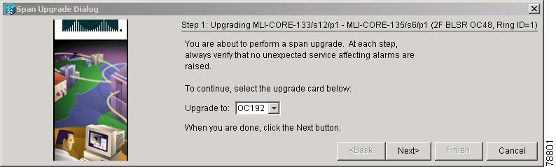
Step 6 ![]() The first Span Upgrade dialog box appears (Figure 12-3). Follow the instructions on the dialog box and the wizard will lead you through the rest of the span upgrade.
The first Span Upgrade dialog box appears (Figure 12-3). Follow the instructions on the dialog box and the wizard will lead you through the rest of the span upgrade.
Note ![]() The Back button is only enabled on Step 2 of the wizard; because you cannot back out of an upgrade via the wizard, close the wizard and initiate the manual procedure if you need to back out of the upgrade at any point beyond Step 2.
The Back button is only enabled on Step 2 of the wizard; because you cannot back out of an upgrade via the wizard, close the wizard and initiate the manual procedure if you need to back out of the upgrade at any point beyond Step 2.
Figure 12-3 Span Upgrade Wizard
Caution
Note ![]() If you install OC-192 cards, a disabled OC-192 laser causes an LOS alarm to be reported for each OC-192 slot. Enable the OC-192 laser by setting the safety key lock on the OC-192 faceplate to the ON position (labeled 1).
If you install OC-192 cards, a disabled OC-192 laser causes an LOS alarm to be reported for each OC-192 slot. Enable the OC-192 laser by setting the safety key lock on the OC-192 faceplate to the ON position (labeled 1).
Note ![]() Remember to attach the fiber after installing the OC-N cards.
Remember to attach the fiber after installing the OC-N cards.
Note ![]() The span upgrade process resets the line's CV-L threshold to factory default. The CV-L threshold is reset because the threshold is dependent on line rate.
The span upgrade process resets the line's CV-L threshold to factory default. The CV-L threshold is reset because the threshold is dependent on line rate.
Step 7 ![]() Repeat Steps 4 through 6 for additional spans in the ring.
Repeat Steps 4 through 6 for additional spans in the ring.
Stop. You have completed this procedure.
NTP-A95 Upgrade Optical Spans Manually
Note ![]() Optical card transmit and receive levels should be in their acceptable range as shown in the specifications section for each card in the Cisco ONS 15454 Reference Manual.
Optical card transmit and receive levels should be in their acceptable range as shown in the specifications section for each card in the Cisco ONS 15454 Reference Manual.
Note ![]() In this context the word "span" represents the optical path between two nodes. The words "span endpoint" represent the nodes on each end of a span.
In this context the word "span" represents the optical path between two nodes. The words "span endpoint" represent the nodes on each end of a span.
Note ![]() If any of the cross-connect cards reboot during the span upgrade, you must reset each one when the span upgrade procedure is complete for all the nodes in the ring.
If any of the cross-connect cards reboot during the span upgrade, you must reset each one when the span upgrade procedure is complete for all the nodes in the ring.
Step 1 ![]() Determine the type of span you need to upgrade and make sure you have the necessary cards.Valid span upgrades include:
Determine the type of span you need to upgrade and make sure you have the necessary cards.Valid span upgrades include:
•![]() Four-port OC-3 to eight-port OC-3
Four-port OC-3 to eight-port OC-3
•![]() Single-port OC-12 to four-port OC-12
Single-port OC-12 to four-port OC-12
•![]() Single-port OC-12 to OC-48
Single-port OC-12 to OC-48
•![]() Single-port OC-12 to OC-192
Single-port OC-12 to OC-192
•![]() OC-48 to OC-192
OC-48 to OC-192
Step 2 ![]() Complete the "DLP-A60 Log into CTC" task on page 3-23. If you are already logged in, continue with Step 3.
Complete the "DLP-A60 Log into CTC" task on page 3-23. If you are already logged in, continue with Step 3.
Step 3 ![]() Ensure that no alarms or abnormal conditions (regardless of severity), including LOS, LOF, AIS-L, SF, SD, and FORCED-REQ-RING are present. See the "DLP-A298 Check the Network for Alarms and Conditions" task on page 13-3 for instructions.
Ensure that no alarms or abnormal conditions (regardless of severity), including LOS, LOF, AIS-L, SF, SD, and FORCED-REQ-RING are present. See the "DLP-A298 Check the Network for Alarms and Conditions" task on page 13-3 for instructions.
Note ![]() During the upgrade/downgrade some minor alarms and conditions display and then clear automatically. No service-affecting alarms (SA, Major, or Critical) should occur other than BLSROSYNC, which will clear when the upgrade/downgrade of all nodes is complete. If any other service-affecting alarms occur, Cisco recommends backing out of the procedure.
During the upgrade/downgrade some minor alarms and conditions display and then clear automatically. No service-affecting alarms (SA, Major, or Critical) should occur other than BLSROSYNC, which will clear when the upgrade/downgrade of all nodes is complete. If any other service-affecting alarms occur, Cisco recommends backing out of the procedure.
A four-node BLSR can take up to five minutes to clear all of the BLSROSYNC alarms. Allow extra time for a large BLSR to clear all of the BLSROSYNC alarms. Refer to the Cisco ONS 15454 Troubleshooting Guide for information about alarms.
Step 4 ![]() Complete a manual upgrade task if you need to perform error recovery for the Span Upgrade Wizard or back out of a span upgrade (downgrade):
Complete a manual upgrade task if you need to perform error recovery for the Span Upgrade Wizard or back out of a span upgrade (downgrade):
•![]() Complete the "DLP-A293 Perform a Manual Span Upgrade on a Two-Fiber BLSR" task to upgrade an optical span manually within a two-fiber BLSR.
Complete the "DLP-A293 Perform a Manual Span Upgrade on a Two-Fiber BLSR" task to upgrade an optical span manually within a two-fiber BLSR.
•![]() Complete the "DLP-A294 Perform a Manual Span Upgrade on a Four-Fiber BLSR" task to upgrade an optical span manually within a four-fiber BLSR.
Complete the "DLP-A294 Perform a Manual Span Upgrade on a Four-Fiber BLSR" task to upgrade an optical span manually within a four-fiber BLSR.
•![]() Complete the "DLP-A295 Perform a Manual Span Upgrade on a Path Protection Configuration" task to upgrade an optical span manually within a two-fiber path protection configuration.
Complete the "DLP-A295 Perform a Manual Span Upgrade on a Path Protection Configuration" task to upgrade an optical span manually within a two-fiber path protection configuration.
•![]() Complete the "DLP-A296 Perform a Manual Span Upgrade on a 1+1 Protection Group" task to upgrade an optical span manually within a 1+1 protection group.
Complete the "DLP-A296 Perform a Manual Span Upgrade on a 1+1 Protection Group" task to upgrade an optical span manually within a 1+1 protection group.
•![]() Complete the "DLP-A297 Perform a Manual Span Upgrade on an Unprotected Span" task to upgrade an unprotected optical span manually.
Complete the "DLP-A297 Perform a Manual Span Upgrade on an Unprotected Span" task to upgrade an unprotected optical span manually.
Note ![]() The span upgrade process resets the line's CV-L threshold to factory default. The CV-L threshold is reset because the threshold is dependent on line rate.
The span upgrade process resets the line's CV-L threshold to factory default. The CV-L threshold is reset because the threshold is dependent on line rate.
Note ![]() The Span Upgrade option will only be visible and available if the hardware necessary for the upgrade is present; for example, no upgrade is possible from an OC48 span unless XC10G cards are installed in the nodes at both ends of the span.
The Span Upgrade option will only be visible and available if the hardware necessary for the upgrade is present; for example, no upgrade is possible from an OC48 span unless XC10G cards are installed in the nodes at both ends of the span.
Note ![]() An OC-3 to eight-port OC-3 span upgrade, or an OC-12 to four-port OC-12 span upgrade can only be performed from multispeed slots (Slots 1 to 4 and 14 to17) because the OC3-8 and OC12-4 card can only be installed in multispeed slots. Ensure that the OC-3 and OC-12 cards are in multispeed slots before performing a span upgrade to the OC3-8 and OC12-4. The four OC-3 ports will be mapped to Ports 1-4 on the eight-port OC-3 card. The OC-12 port will be mapped to Port 1 on the four-port OC-12 card.
An OC-3 to eight-port OC-3 span upgrade, or an OC-12 to four-port OC-12 span upgrade can only be performed from multispeed slots (Slots 1 to 4 and 14 to17) because the OC3-8 and OC12-4 card can only be installed in multispeed slots. Ensure that the OC-3 and OC-12 cards are in multispeed slots before performing a span upgrade to the OC3-8 and OC12-4. The four OC-3 ports will be mapped to Ports 1-4 on the eight-port OC-3 card. The OC-12 port will be mapped to Port 1 on the four-port OC-12 card.
Stop. You have completed this procedure.
DLP-A293 Perform a Manual Span Upgrade on a Two-Fiber BLSR
Warning ![]() Do not reach into a vacant slot or chassis while you install or remove a module or a fan. Exposed circuitry could constitute an energy hazard.
Do not reach into a vacant slot or chassis while you install or remove a module or a fan. Exposed circuitry could constitute an energy hazard.
Note ![]() All spans connecting the nodes in a BLSR must be upgraded before the bandwidth is available.
All spans connecting the nodes in a BLSR must be upgraded before the bandwidth is available.
Note ![]() BLSR protection channel access (PCA) circuits, if present, will remain in their existing STSs. Therefore, they will be located on the working path of the upgraded span and will have full BLSR protection. To route PCA circuits on protection channels in the upgraded span, delete and recreate the circuits after the span upgrade. For example, if you upgrade an OC-48 span to an OC-192, PCA circuits on the protection STSs (STSs 25 to 48) in the OC-48 BLSR will remain in their existing STSs (STSs 25 to 48) which are working, protected STSs in the OC-192 BLSR. Deleting and recreating the OC-48 PCA circuits moves the circuits to STSs 96 to 192 in the OC-192 BLSR. To delete circuits, see the "NTP-A152 Delete Circuits" procedure on page 9-16. To create circuits, see Chapter 6, "Create Circuits and VT Tunnels."
BLSR protection channel access (PCA) circuits, if present, will remain in their existing STSs. Therefore, they will be located on the working path of the upgraded span and will have full BLSR protection. To route PCA circuits on protection channels in the upgraded span, delete and recreate the circuits after the span upgrade. For example, if you upgrade an OC-48 span to an OC-192, PCA circuits on the protection STSs (STSs 25 to 48) in the OC-48 BLSR will remain in their existing STSs (STSs 25 to 48) which are working, protected STSs in the OC-192 BLSR. Deleting and recreating the OC-48 PCA circuits moves the circuits to STSs 96 to 192 in the OC-192 BLSR. To delete circuits, see the "NTP-A152 Delete Circuits" procedure on page 9-16. To create circuits, see Chapter 6, "Create Circuits and VT Tunnels."
Step 1 ![]() Apply a Force switch to both span endpoints (nodes) on the span that you will upgrade first. See the "DLP-A303 Initiate a BLSR Force Switch - Ring" task on page 14-7.
Apply a Force switch to both span endpoints (nodes) on the span that you will upgrade first. See the "DLP-A303 Initiate a BLSR Force Switch - Ring" task on page 14-7.
Note ![]() A Force switch request on a span or card causes CTC to raise a FORCED-REQ condition. It is informational only; the condition will clear when the Force switch is cleared.
A Force switch request on a span or card causes CTC to raise a FORCED-REQ condition. It is informational only; the condition will clear when the Force switch is cleared.
Step 2 ![]() Remove the fiber from both endpoints and ensure that traffic is still running.
Remove the fiber from both endpoints and ensure that traffic is still running.
Step 3 ![]() Remove the OC-N cards from both endpoints.
Remove the OC-N cards from both endpoints.
Step 4 ![]() From both endpoints, in node view right-click each OC-N slot and choose Change Card.
From both endpoints, in node view right-click each OC-N slot and choose Change Card.
Step 5 ![]() In the Change Card dialog box, choose the new OC-N card type.
In the Change Card dialog box, choose the new OC-N card type.
Step 6 ![]() Click OK.
Click OK.
Step 7 ![]() Before attaching the fiber to the newly installed OC-N cards, check that the transmit signal falls within the acceptable range. Install the new OC-N cards in both endpoints and attach the fiber to the cards. Wait for the IMPROPRMVL alarm to clear and the cards to become active.
Before attaching the fiber to the newly installed OC-N cards, check that the transmit signal falls within the acceptable range. Install the new OC-N cards in both endpoints and attach the fiber to the cards. Wait for the IMPROPRMVL alarm to clear and the cards to become active.
Note ![]() If you install OC-192 cards, a disabled OC-192 laser causes an LOS alarm to be reported for each OC-192 slot. Enable the OC-192 laser by setting the safety key lock on the OC-192 faceplate to the ON position (labeled 1).
If you install OC-192 cards, a disabled OC-192 laser causes an LOS alarm to be reported for each OC-192 slot. Enable the OC-192 laser by setting the safety key lock on the OC-192 faceplate to the ON position (labeled 1).
Step 8 ![]() When cards in both endpoint nodes have been successfully upgraded and all the facility alarms (LOS, SD or SF) are cleared, remove the forced switch from both endpoints on the upgraded span. Seethe "DLP-A194 Clear a BLSR Force Switch - Ring" task on page 14-9.
When cards in both endpoint nodes have been successfully upgraded and all the facility alarms (LOS, SD or SF) are cleared, remove the forced switch from both endpoints on the upgraded span. Seethe "DLP-A194 Clear a BLSR Force Switch - Ring" task on page 14-9.
The Force switch clears and traffic is running. If you have lost traffic, perform a downgrade. Repeat this task to downgrade but choose a lower-rate card in Step 5.
Step 9 ![]() Repeat this task for each span in the BLSR. When you are done with each span, the upgrade is complete.
Repeat this task for each span in the BLSR. When you are done with each span, the upgrade is complete.
Step 10 ![]() Return to your originating procedure (NTP).
Return to your originating procedure (NTP).
DLP-A294 Perform a Manual Span Upgrade on a Four-Fiber BLSR
Warning ![]() Do not reach into a vacant slot or chassis while you install or remove a module or a fan. Exposed circuitry could constitute an energy hazard.
Do not reach into a vacant slot or chassis while you install or remove a module or a fan. Exposed circuitry could constitute an energy hazard.
Note ![]() All spans connecting the nodes in a BLSR must be upgraded before the bandwidth is available.
All spans connecting the nodes in a BLSR must be upgraded before the bandwidth is available.
Note ![]() BLSR protection channel access (PCA) circuits, if present, will remain in their existing STSs. Therefore, they will be located on the working path of the upgraded span and will have full BLSR protection. To route PCA circuits on protection channels in the upgraded span, delete and recreate the circuits after the span upgrade. For example, if you upgrade an OC-48 span to an OC-192, PCA circuits on the protection STSs (STSs 25 to 48) in the OC-48 BLSR will remain in their existing STSs (STSs 25 to 48) which are working, protected STSs in the OC-192 BLSR. Deleting and recreating the OC-48 PCA circuits moves the circuits to STSs 96 to 192 in the OC-192 BLSR. To delete circuits, see the "NTP-A152 Delete Circuits" procedure on page 9-16. To create circuits, see Chapter 6, "Create Circuits and VT Tunnels."
BLSR protection channel access (PCA) circuits, if present, will remain in their existing STSs. Therefore, they will be located on the working path of the upgraded span and will have full BLSR protection. To route PCA circuits on protection channels in the upgraded span, delete and recreate the circuits after the span upgrade. For example, if you upgrade an OC-48 span to an OC-192, PCA circuits on the protection STSs (STSs 25 to 48) in the OC-48 BLSR will remain in their existing STSs (STSs 25 to 48) which are working, protected STSs in the OC-192 BLSR. Deleting and recreating the OC-48 PCA circuits moves the circuits to STSs 96 to 192 in the OC-192 BLSR. To delete circuits, see the "NTP-A152 Delete Circuits" procedure on page 9-16. To create circuits, see Chapter 6, "Create Circuits and VT Tunnels."
Step 1 ![]() Apply a Force switch to both span endpoints (nodes) on the span that you will upgrade first. See the "DLP-A303 Initiate a BLSR Force Switch - Ring" task on page 14-7.
Apply a Force switch to both span endpoints (nodes) on the span that you will upgrade first. See the "DLP-A303 Initiate a BLSR Force Switch - Ring" task on page 14-7.
Note ![]() A Force switch request on a span or card causes CTC to raise a FORCED-REQ condition. It is informational only; the condition will clear when the Force switch command is cleared.
A Force switch request on a span or card causes CTC to raise a FORCED-REQ condition. It is informational only; the condition will clear when the Force switch command is cleared.
Step 2 ![]() Remove the fiber from both working and protect cards at both span endpoints (nodes) and ensure that traffic is still running.
Remove the fiber from both working and protect cards at both span endpoints (nodes) and ensure that traffic is still running.
Step 3 ![]() Remove the OC-N cards from both end points.
Remove the OC-N cards from both end points.
Step 4 ![]() For both ends of the span endpoints, in node view right-click each OC-N slot and choose Change Card.
For both ends of the span endpoints, in node view right-click each OC-N slot and choose Change Card.
Step 5 ![]() In the Change Card dialog box, choose the new OC-N card type.
In the Change Card dialog box, choose the new OC-N card type.
Step 6 ![]() Click OK.
Click OK.
Step 7 ![]() Before attaching the fiber to the newly installed OC-N cards, check that the transmit signal falls within the acceptable range. Install the new OC-N cards in both endpoints and attach the fiber to the cards. Wait for the IMPROPRMVL alarm to clear and the cards to become active.
Before attaching the fiber to the newly installed OC-N cards, check that the transmit signal falls within the acceptable range. Install the new OC-N cards in both endpoints and attach the fiber to the cards. Wait for the IMPROPRMVL alarm to clear and the cards to become active.
Note ![]() If you install OC-192 cards, a disabled OC-192 laser causes an LOS alarm to be reported for each OC-192 slot. Enable the OC-192 laser by setting the safety key lock on the OC-192 faceplate to the ON position (labeled 1).
If you install OC-192 cards, a disabled OC-192 laser causes an LOS alarm to be reported for each OC-192 slot. Enable the OC-192 laser by setting the safety key lock on the OC-192 faceplate to the ON position (labeled 1).
Step 8 ![]() When cards in both endpoint nodes have been successfully upgraded and all the facility alarms (LOS, SD or SF) are cleared, remove the forced switch from both endpoints (nodes) on the upgraded span. See "194 Clear a BLSR Force Switch - Ring" section on page 14-9.
When cards in both endpoint nodes have been successfully upgraded and all the facility alarms (LOS, SD or SF) are cleared, remove the forced switch from both endpoints (nodes) on the upgraded span. See "194 Clear a BLSR Force Switch - Ring" section on page 14-9.
The forced switch clears and traffic is running. If you have lost traffic, perform a downgrade. Repeat this task to downgrade but choose a lower-rate card in Step 5.
Step 9 ![]() Repeat these steps for each span in the BLSR. When all spans in the BLSR have been upgraded, the ring is upgraded.
Repeat these steps for each span in the BLSR. When all spans in the BLSR have been upgraded, the ring is upgraded.
Step 10 ![]() Return to your originating procedure (NTP).
Return to your originating procedure (NTP).
DLP-A295 Perform a Manual Span Upgrade on a Path Protection Configuration
Warning ![]() Do not reach into a vacant slot or chassis while you install or remove a module or a fan. Exposed circuitry could constitute an energy hazard.
Do not reach into a vacant slot or chassis while you install or remove a module or a fan. Exposed circuitry could constitute an energy hazard.
Step 1 ![]() Complete the "DLP-A197 Initiate a Path Protection Configuration Force Switch" task on page 14-18 to apply a Force switch on the span that you will upgrade.
Complete the "DLP-A197 Initiate a Path Protection Configuration Force Switch" task on page 14-18 to apply a Force switch on the span that you will upgrade.
Step 2 ![]() Remove the fiber from both endpoint nodes in the span and ensure that traffic is still running.
Remove the fiber from both endpoint nodes in the span and ensure that traffic is still running.
Step 3 ![]() Remove the OC-N cards from both span endpoints.
Remove the OC-N cards from both span endpoints.
Step 4 ![]() For both ends of the span, in node view right-click each OC-N slot and choose Change Card.
For both ends of the span, in node view right-click each OC-N slot and choose Change Card.
Step 5 ![]() In the Change Card dialog box, choose the new OC-N card type.
In the Change Card dialog box, choose the new OC-N card type.
Step 6 ![]() Click OK.
Click OK.
Step 7 ![]() Before attaching the fiber to the newly installed OC-N cards, check that the transmit signal falls within the acceptable range. Install the new OC-N cards in both endpoints and attach the fiber to the cards. Wait for the IMPROPRMVL alarm to clear and the cards to become active.
Before attaching the fiber to the newly installed OC-N cards, check that the transmit signal falls within the acceptable range. Install the new OC-N cards in both endpoints and attach the fiber to the cards. Wait for the IMPROPRMVL alarm to clear and the cards to become active.
Note ![]() If you install OC-192 cards, a disabled OC-192 laser causes an LOS alarm to be reported for each OC-192 slot. Enable the OC-192 laser by setting the safety key lock on the OC-192 faceplate to the ON position (labeled 1).
If you install OC-192 cards, a disabled OC-192 laser causes an LOS alarm to be reported for each OC-192 slot. Enable the OC-192 laser by setting the safety key lock on the OC-192 faceplate to the ON position (labeled 1).
Step 8 ![]() Complete the "DLP-A198 Clear a Path Protection Configuration Force Switch" task on page 14-19 when cards in both endpoint nodes have been successfully upgraded and all the facility alarms (LOS, SD or SF) are cleared.
Complete the "DLP-A198 Clear a Path Protection Configuration Force Switch" task on page 14-19 when cards in both endpoint nodes have been successfully upgraded and all the facility alarms (LOS, SD or SF) are cleared.
The forced switch clears and traffic is running. If you have lost traffic, perform a downgrade. Repeat this task to downgrade but choose a lower-rate card in Step 5.
Step 9 ![]() Return to your originating procedure (NTP).
Return to your originating procedure (NTP).
DLP-A296 Perform a Manual Span Upgrade on a 1+1 Protection Group
Warning ![]() Do not reach into a vacant slot or chassis while you install or remove a module or a fan. Exposed circuitry could constitute an energy hazard.
Do not reach into a vacant slot or chassis while you install or remove a module or a fan. Exposed circuitry could constitute an energy hazard.
Step 1 ![]() Complete the "DLP-A287 Switch 1+1 Traffic" task to apply a Force switch to the protect port on the span you will upgrade.
Complete the "DLP-A287 Switch 1+1 Traffic" task to apply a Force switch to the protect port on the span you will upgrade.
Note ![]() If the switching mode is bidirectional in the 1+1 protection group, apply the Force command to only one end of the span. If the Force command is applied to both ends when the switching mode is bidirectional, it will cause a switch of more than 50 ms in duration.
If the switching mode is bidirectional in the 1+1 protection group, apply the Force command to only one end of the span. If the Force command is applied to both ends when the switching mode is bidirectional, it will cause a switch of more than 50 ms in duration.
Step 2 ![]() Repeat Step 1 for each port you will upgrade.
Repeat Step 1 for each port you will upgrade.
Step 3 ![]() Remove the fiber from both ends of the span and ensure that traffic is still running.
Remove the fiber from both ends of the span and ensure that traffic is still running.
Step 4 ![]() Remove the OC-N cards from both span endpoints.
Remove the OC-N cards from both span endpoints.
Step 5 ![]() At both ends of the span, in node view, right-click the OC-N slot and choose Change Card.
At both ends of the span, in node view, right-click the OC-N slot and choose Change Card.
Step 6 ![]() In the Change Card dialog box, choose the new OC-N card type.
In the Change Card dialog box, choose the new OC-N card type.
Step 7 ![]() Click OK.
Click OK.
Step 8 ![]() Before attaching the fiber to the newly installed OC-N cards, verify that the transmit signal falls within the acceptable range. Install the new OC-N cards in both endpoints and attach the fiber to the cards. Wait for the IMPROPRMVL alarm to clear and the cards to become standby.
Before attaching the fiber to the newly installed OC-N cards, verify that the transmit signal falls within the acceptable range. Install the new OC-N cards in both endpoints and attach the fiber to the cards. Wait for the IMPROPRMVL alarm to clear and the cards to become standby.
Note ![]() If you install OC-192 cards, a disabled OC-192 laser causes an LOS alarm to be reported for each OC-192 slot. Enable the OC-192 laser by setting the safety key lock on the OC-192 faceplate to the ON position (labeled 1).
If you install OC-192 cards, a disabled OC-192 laser causes an LOS alarm to be reported for each OC-192 slot. Enable the OC-192 laser by setting the safety key lock on the OC-192 faceplate to the ON position (labeled 1).
Step 9 ![]() When cards on each end of the span have been successfully upgraded and all the facility alarms (LOS, SD or SF) are cleared, complete the "DLP-A288 Clear a 1+1 Traffic Switch" task to remove the Force switch.
When cards on each end of the span have been successfully upgraded and all the facility alarms (LOS, SD or SF) are cleared, complete the "DLP-A288 Clear a 1+1 Traffic Switch" task to remove the Force switch.
The Force switch clears and traffic is running. If you have lost traffic, perform a downgrade. Repeat this task to downgrade but choose a lower-rate card in Step 6.
Step 10 ![]() Repeat this task for any other spans in the 1 + 1 linear configuration.
Repeat this task for any other spans in the 1 + 1 linear configuration.
Step 11 ![]() Return to your originating procedure (NTP).
Return to your originating procedure (NTP).
DLP-A297 Perform a Manual Span Upgrade on an Unprotected Span
Warning ![]() Do not reach into a vacant slot or chassis while you install or remove a module or a fan. Exposed circuitry could constitute an energy hazard.
Do not reach into a vacant slot or chassis while you install or remove a module or a fan. Exposed circuitry could constitute an energy hazard.
Step 1 ![]() Remove the fiber from both endpoint nodes in the span.
Remove the fiber from both endpoint nodes in the span.
Step 2 ![]() Remove the OC-N cards from both span endpoints.
Remove the OC-N cards from both span endpoints.
Step 3 ![]() For both ends of the span, in node view, right-click each OC-N slot and choose Change Card.
For both ends of the span, in node view, right-click each OC-N slot and choose Change Card.
Step 4 ![]() In the Change Card dialog box, choose the new OC-N type.
In the Change Card dialog box, choose the new OC-N type.
Step 5 ![]() Click OK.
Click OK.
Step 6 ![]() When you have finished Steps 2 - 5 for both nodes, install the new OC-N cards in both endpoints and attach the fiber to the cards. Wait for the IMPROPRMVL alarm to clear and the cards to become active.
When you have finished Steps 2 - 5 for both nodes, install the new OC-N cards in both endpoints and attach the fiber to the cards. Wait for the IMPROPRMVL alarm to clear and the cards to become active.
Note ![]() If you install OC-192 cards, a disabled OC-192 laser causes an LOS alarm to be reported for each OC-192 slot. Enable the OC-192 laser by setting the safety key lock on the OC-192 faceplate to the ON position (labeled 1).
If you install OC-192 cards, a disabled OC-192 laser causes an LOS alarm to be reported for each OC-192 slot. Enable the OC-192 laser by setting the safety key lock on the OC-192 faceplate to the ON position (labeled 1).
Step 7 ![]() Return to your originating procedure (NTP).
Return to your originating procedure (NTP).
 Feedback