Configuring Wireless Devices

This chapter describes the procedures for initial configuration of the wireless device, radio settings, WLAN, and administration of the wireless devices. This chapter contains the following sub-sections:

Embedded IOS Wireless Access Points (for AP801/AP802/AP803)

This section describes how to configure wireless devices for the embedded IOS Wireless Access Points (for AP801/AP802/AP803).

Wireless LAN Overview

Wireless devices (commonly configured as access points ) provide a secure, affordable, and easy-to-use wireless LAN solution that combines mobility and flexibility with the enterprise-class features required by networking professionals. When configured as an access point, the wireless device serves as the connection point between wireless and wired networks or as the center point of a stand-alone wireless network. In large installations, wireless users within radio range of an access point can roam throughout a facility while maintaining seamless, uninterrupted access to the network.

With a management system based on Cisco IOS software, wireless devices are Wi-Fi CERTIFIED™, 802.11a-compliant, 802.11b-compliant, 802.11g-compliant, and 802.11n-compliant wireless LAN transceivers.

Software Modes for Wireless Devices

The access point is shipped with an autonomous image and recovery image on the access point’s flash. The default mode is autonomous; however, the access point can be upgraded to operate in Cisco Unified Wireless mode.

Each mode is described below:

  • Autonomous mode—supports standalone network configurations, where all configuration settings are maintained locally on the wireless device. Each autonomous device can load its starting configuration independently, and still operate in a cohesive fashion on the network.
  • Cisco Unified Wireless mode—operates in conjunction with a Cisco Unified Wireless LAN controller, where all configuration information is maintained within the controller. In the Cisco Unified Wireless LAN architecture, wireless devices operate in the lightweight mode using Leightweight Access Point Protocol (LWAPP), (as opposed to autonomous mode). The lightweight access point, or wireless device, has no configuration until it associates to a controller. The configuration on the wireless device can be modified by the controller only when the networking is up and running. The controller manages the wireless device configuration, firmware, and control transactions such as 802.1x authentication. All wireless traffic is tunneled through the controller.

For more information about Cisco Unified Wireless mode, see http:/​/​www.cisco.com/​en/​US/​prod/​collateral/​wireless/​ps5679/​ps6548/​prod_​white_​paper0900aecd804f19e3_​ps6305_​Products_​White_​Paper.html .

Management Options for Wireless Device

The wireless device runs its own version of Cisco IOS software that is separate from the Cisco IOS software operating on the router. You can configure and monitor the access point with several different tools:

  • Cisco IOS software CLI
  • Simple Network Management Protocol (SNMP)
  • Web-browser Interface

Note


Avoid using the CLI and the web-browser tools concurrently. If you configure the wireless device using the CLI, the web-browser interface may display an inaccurate interpretation of the configuration.

Use the interface dot11radio command from global configuration mode to place the wireless device into the radio configuration mode. Network Configuration Examples

Set up the access point role in any of these common wireless network configurations. The access point default configuration is as a root unit connected to a wired LAN or as the central unit in an all-wireless network. Access points can also be configured as bridges and workgroup bridges. These roles require specific configurations, as defined in the following examples.

Root Access Point

An access point connected directly to a wired LAN provides a connection point for wireless users. If more than one access point is connected to the LAN, users can roam from one area of a facility to another without losing their connection to the network. As users move out of range of one access point, they automatically connect to the network (associate) through another access point. The roaming process is seamless and transparent to the user. Figure 1 shows access points acting as root units on a wired LAN.

Figure 1. Access Points as Root Units on a Wired LAN

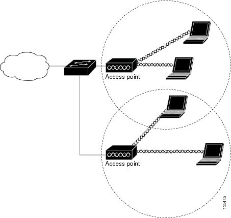
Central Unit in an All-Wireless Network

In an all-wireless network, an access point acts as a stand-alone root unit. The access point is not attached to a wired LAN; it functions as a hub linking all stations together. The access point serves as the focal point for communications, increasing the communication range of wireless users. Figure 1 shows an access point in an all-wireless network.

Figure 2. Access Point as Central Unit in All-Wireless Network

Basic Wireless Configuration for Cisco 800 Series ISR

This module describes how to configure the autonomous wireless device on the following Cisco Integrated Services Routers (ISRs):

  • Cisco 860 Series
  • Cisco 880 Series
  • Cisco 890 Series
  • Cisco 810 Series

Note


To upgrade the autonomous software to Cisco Unified software on the embedded wireless device, see the Upgrading to Cisco Unified Software for instructions.

The wireless device is embedded and does not have an external console port for connections. To configure the wireless device, use a console cable to connect a personal computer to the host router’s console port, and perform these procedures to establish connectivity and configure the wireless settings.

Starting a Wireless Configuration Session


Note


Before you configure the wireless settings in the router’s setup, you must follow step 1 and 2 to open a session between the router and the access point.

Note


Step 1 and 2 are not required in releases prior to Release 15.5(03)M06.


Enter the following commands in global configuration mode on the router’s Cisco IOS command-line interface (CLI).

SUMMARY STEPS

    1.    line line number

    2.    transport input all

    3.    interface wlan-ap0

    4.    ip address subnet mask

    5.    no shut

    6.    interface vlan1

    7.    ip address subnet mask

    8.    exit

    9.    exit

    10.    service-module wlan-ap 0 session


DETAILED STEPS
     Command or ActionPurpose
    Step 1line line number


    Example:
    Router(config)# line 2
     

    Identifies a specific line for configuration and enters the line configuration collection mode.

    Note   

    This step is not required in releases prior to Release 15.5(03)M06.

     
    Step 2transport input all


    Example:
    Router(config)# transport input all
     

    Assigns the device or interface as the designated-gateway for the domain.

    Note   

    This step is not required in releases prior to Release 15.5(03)M06.

     
    Step 3interface wlan-ap0


    Example:
    Router(config)# interface wlan-ap0
     

    Defines the router’s console interface to the wireless device.

    • The interface is used for communication between the router’s console and the wireless device.
    Note    Always use port 0.
    • The following message appears:
    The wlan-ap 0 interface is used for managing the embedded AP. Please use the service-module wlan-ap 0 session command to console into the embedded AP.
     
    Step 4ip address subnet mask


    Example:
    Router(config-if)# ip address 10.21.0.20 255.255.255.0
     

    Specifies the interface IP address and subnet mask.

    Note    The IP address can be shared with the IP address assigned to the Cisco Integrated Services Router by using the ip unnumbered vlan1 command.
     
    Step 5no shut


    Example:
    Router(config-if)# no shut
     

    Specifies that the internal interface connection will remain open.

     
    Step 6interface vlan1


    Example:
    Router(config-if)# interface vlan1
     

    Specifies the virtual LAN interface for data communication on the internal Gigabit Ethernet 0 (GE0) port to other interfaces.

    • All the switch ports inherit the default vlan1 interface on the Cisco 860 Series, Cisco 880 Series, and Cisco 890 Series ISRs.
     
    Step 7ip address subnet mask


    Example:
    Router(config-if)# ip address 10.10.0.30 255.255.255.0
     

    Specifies the interface IP address and subnet mask.

     
    Step 8exit


    Example:
    Router(config-if)# exit


    Example:
    Router(config)#
     

    Exits interface configuration mode and returns to global configuration mode.

     
    Step 9exit


    Example:
    Router(config)# exit


    Example:
    Router#
     

    Exits the global configuration mode.

     
    Step 10service-module wlan-ap 0 session


    Example:
    Router# service-module wlan-ap0 session
    Trying 10.21.0.20, 2002 ... Open
    ap>
     

    Opens the connection between the wireless device and the router’s console.

     
    What to Do Next


    Tip


    To create a Cisco IOS software alias for the console to session into the wireless device, enter the alias exec dot11radio service-module wlan-ap 0 session command at the EXEC prompt. After entering this command, you utomatically skip to the dot11 radio level in the Cisco IOS software.


    Closing the Session

    To close the session between the wireless device and the router’s console, use control+shift+6 and x on the wireless device and enter disconnect command on the router and then press enter two times on the router.

    Configuring Wireless Settings


    Note


    If you are configuring the wireless device for the first time, you must start a configuration session between the access point and the router before you attempt to configure the basic wireless settings. See the Starting a Wireless Configuration Session.

    Configure the wireless device with either of the following tools, depending on the software you are using:


    Note


    To upgrade to Unified mode from the Autonomous mode, see Upgrading to Cisco Unified Software for upgrade instructions. After upgrading to Cisco Unified Wireless software, use the web-browser tool to configure the device:

    http:/​/​cisco.com/​en/​US/​docs/​wireless/​access_point/​12.4_10b_JA/​configuration/​guide/​scg12410b-chap2-gui.html

    Cisco Express Setup

    To configure the Unified wireless device, use the web-browser tool and perform these steps

    1. Establish a console connection to the wireless device and get the Bridge-Group Virtual Interface (BVI) IP address by entering the show interface bvi1 Cisco IOS command.
    2. Open a browser window, and enter the BVI IP address in the browser-window address line. Press Enter. An Enter Network Password window appears.
    3. Enter your username. Cisco is the default user name.
    4. Enter the wireless device password. Cisco is the default password. The Summary Status page appears. For details about using the web-browser configuration page, see the following URL:

      http:/​/​cisco.com/​en/​US/​docs/​wireless/​access_point/​12.4_10b_JA/​configuration/​guide/​scg12410b-chap4-first.html#wp1103336

    Cisco IOS Command Line Interface

    To configure the Autonomous wireless device, use the Cisco IOS CLI tool and perform these tasks:

    Configuring the Radio

    Configure the radio parameters on the wireless device to transmit signals in autonomous or Cisco Unified mode. For specific configuration procedures, see Configuring Radio Settings.

    Configuring Wireless Security Settings

    This section includes the following configuration tasks:

    Configuring Authentication

    Authentication types are tied to the Service Set Identifiers (SSIDs) that are configured for the access point. To serve different types of client devices with the same access point, configure multiple SSIDs.

    Before a wireless client device can communicate on your network through the access point, the client device must authenticate to the access point by using open or shared-key authentication. For maximum security, client devices should also authenticate to your network using MAC address or Extensible Authentication Protocol (EAP) authentication. Both authentication types rely on an authentication server on your network.

    To select an authentication type, see Authentication Types for Wireless Devices at:

    http:/​/​www.cisco.com/​en/​US/​docs/​routers/​access/​wireless/​software/​guide/​SecurityAuthentication Types.html.

    To set up a maximum security environment, see RADIUS and TACACS+ Servers in a Wireless Environment at:

    http:/​/​www.cisco.com/​en/​US/​docs/​routers/​access/​wireless/​software/​guide/​SecurityRadiusTacacs_​1.html

    To provide local authentication service or backup authentication service for a WAN link failure or a server failure, you can configure an access point to act as a local authentication server. The access point can authenticate up to 50 wireless client devices using Lightweight Extensible Authentication Protocol (LEAP), Extensible Authentication Protocol-Flexible Authentication via Secure Tunneling (EAP-FAST), or MAC-based authentication. The access point performs up to five authentications per second.

    Configure the local authenticator access point manually with client usernames and passwords because it does not synchronize its database with RADIUS servers. You can specify a VLAN and a list of SSIDs that a client is allowed to use.

    For details about setting up the wireless device in this role, see Using the Access Point as a Local Authenticator at:

    http:/​/​www.cisco.com/​en/​US/​docs/​routers/​access/​wireless/​software/​guide/​SecurityLocalAuthent.html

    Configuring WEP and Cipher Suites

    Wired Equivalent Privacy (WEP) encryption scrambles the data transmitted between wireless devices to keep the communication private. Wireless devices and their wireless client devices use the same WEP key to encrypt and decrypt data. WEP keys encrypt both unicast and multicast messages. Unicast messages are addressed to one device on the network. Multicast messages are addressed to multiple devices on the network.

    Cipher suites are sets of encryption and integrity algorithms designed to protect radio communication on your wireless LAN. You must use a cipher suite to enable Wi-Fi Protected Access (WPA) or Cisco Centralized Key Management (CCKM).

    Cipher suites that contain Temporal Key Integrity Protocol (TKIP) provide the greatest security for your wireless LAN. Cipher suites that contain only WEP are the least secure.

    For encryption procedures, see Configuring WEP and Cipher Suites at:

    http:/​/​www.cisco.com/​en/​US/​docs/​routers/​access/​wireless/​software/​guide/​SecurityCipherSuitesWEP.html

    Configuring Wireless VLANs and Assigning SSIDs

    If you use VLANs on your wireless LAN and assign SSIDs to VLANs, you can create multiple SSIDs by using any of the four security settings defined in the Table 1. A VLAN can be thought of as a broadcast domain that exists within a defined set of switches. A VLAN consists of a number of end systems, either hosts or network equipment (such as bridges and routers), that are connected by a single bridging domain. The bridging domain is supported on various pieces of network equipment, such as LAN switches that operate bridging protocols between them with a separate group of protocols for each VLAN.

    For more information about wireless VLAN architecture, see Configuring Wireless VLANs at:

    http:/​/​www.cisco.com/​en/​US/​docs/​routers/​access/​wireless/​software/​guide/​wireless_​vlans.html


    Note


    If you do not use VLANs on your wireless LAN, the security options that you can assign to SSIDs are limited because the encryption settings and authentication types are linked on the Express Security page.

    You can configure up to 16 SSIDs on a wireless device in the role of an access point, and you can configure a unique set of parameters for each SSID. For example, you might use one SSID to allow guests limited access to the network and another SSID to allow authorized users access to secure data.

    For more about creating multiple SSIDs, see Service Set Identifiers at:

    http:/​/​www.cisco.com/​en/​US/​docs/​routers/​access/​wireless/​software/​guide/​ServiceSetID.html .


    Note


    Without VLANs, encryption settings (WEP and ciphers) apply to an interface, such as the 2.4-GHz radio, and you cannot use more than one encryption setting on an interface. For example, when you create an SSID with static WEP with VLANs disabled, you cannot create additional SSIDs with WPA authentication because the SSIDs use different encryption settings. If the security setting for an SSID conflicts with the settings for another SSID, delete one or more SSIDs to eliminate the conflict.
    Security Types

    Table 1 describes the four security types that you can assign to an SSID.

    Table 1 Types of SSID Security

    Security Type

    Description

    Security Features Enabled

    No security

    This is the least secure option. You should use this option only for SSIDs in a public space, and you should assign it to a VLAN that restricts access to your network.

    None.

    Static WEP key

    This option is more secure than no security. However, static WEP keys are vulnerable to attack. If you configure this setting, you should consider limiting association to the wireless device based on MAC address, see Cipher Suites and WEP at: http:/​/​www.cisco.com/​en/​US/​docs/​routers/​access/​wireless/​software/​guide/​SecurityCipherSuitesWEP.html. Or

    If your network does not have a RADIUS server, consider using an access point as a local authentication server. See Using the Access Point as a Local Authenticator for instructions: http:/​/​www.cisco.com/​en/​US/​docs/​routers/​access/​wireless/​software/​guide/​SecurityLocalAuthent.html.

    Mandatory WEP. Client devices cannot associate using this SSID without a WEP key that matches the wireless device key.

    EAP1 authentication

    This option enables 802.1X authentication (such as LEAP2, PEAP3, EAP-TLS4, EAP-FAST5, EAP-TTLS6, EAP-GTC7, EAP-SIM8, and other 802.1X/EAP-based products)

    This setting uses mandatory encryption, WEP, open authentication plus EAP, network EAP authentication, no key management, and RADIUS server authentication port 1645.

    You are required to enter the IP address and shared secret for an authentication server on your network (server authentication port 1645). Because 802.1X authentication provides dynamic encryption keys, you do not need to enter a WEP key.

    Mandatory 802.1X authentication. Client devices that associate using this SSID must perform 802.1X authentication.

    If radio clients are configured to authenticate using EAP-FAST, open authentication with EAP should also be configured. If you do not configure open authentication with EAP, the following warning message appears:

    SSID CONFIG WARNING: [SSID]: If radio clients are using EAP-FAST, AUTH OPEN with EAP should also be configured.

    WPA9

    This option permits wireless access to users who are authenticated against a database. Access is through the services of an authentication server. User IP traffic is then encrypted with stronger algorithms than those used in WEP.

    This setting uses encryption ciphers, TKIP10, open authentication plus EAP, network EAP authentication, key management WPA mandatory, and RADIUS server authentication port 1645.

    As with EAP authentication, you must enter the IP address and shared secret for an authentication server on your network (server authentication port 1645).

    Mandatory WPA authentication. Client devices that associate using this SSID must be WPA capable.

    If radio clients are configured to authenticate using EAP-FAST, open authentication with EAP should also be configured. If you do not configure open authentication with EAP, the following warning message appears:

    SSID CONFIG WARNING: [SSID]: If radio clients are using EAP-FAST, AUTH OPEN with EAP should also be configured.
    1 EAP = Extensible Authentication Protocol.
    2 LEAP = Lightweight Extensible Authentication Protocol.
    3 PEAP = Protected Extensible Authentication Protocol.
    4 EAP-TLS = Extensible Authentication Protocol—Transport Layer Security.
    5 EAP-FAST = Extensible Authentication Protocol—Flexible Authentication via Secure Tunneling.
    6 EAP-TTLS = Extensible Authentication Protocol—Tunneled Transport Layer Security.
    7 EAP-GTC = Extensible Authentication Protocol—Generic Token Card.
    8 EAP-SIM = Extensible Authentication Protocol—Subscriber Identity Module.
    9 WPA = Wi-Fi Protected Access.
    10 TKIP = Temporal Key Integrity Protocol.
    Configuring Wireless Quality of Service

    Configuring Quality of Service (QoS) can provide preferential treatment to certain traffic at the expense of other traffic. Without QoS, the device offers best-effort service to each packet, regardless of the packet contents or size. It sends the packets without any assurance of reliability, delay bounds, or throughput. To configure QoS for your wireless device, see Quality of Service in a Wireless Environment at:

    http:/​/​www.cisco.com/​en/​US/​docs/​routers/​access/​wireless/​software/​guide/​QualityOfService.html.

    Configuring the Access Point in Hot Standby Mode

    In hot standby mode, an access point is designated as a backup for another access point. The standby access point is placed near the access point that it monitors and is configured exactly like the monitored access point. The standby access point associates with the monitored access point as a client and sends Internet Access Point Protocol (IAPP) queries to the monitored access point through the Ethernet and radio ports. If the monitored access point fails to respond, the standby access point comes online and takes the monitored access point’s place in the network.

    Except for the IP address, the standby access point’s settings should be identical to the settings on the monitored access point. If the monitored access point goes off line and the standby access point takes its place in the network, matching settings ensure that client devices can switch easily to the standby access point. For more information, see Hot Standby Access Points at:

    http:/​/​www.cisco.com/​en/​US/​docs/​routers/​access/​wireless/​software/​guide/​RolesHotStandby.html.

    Upgrading to Cisco Unified Software

    To run the access point in Cisco Unified mode, upgrade the software by performing the following procedures:

    Software Prerequisites
    • Cisco 890 Series ISRs with embedded access points can be upgraded from autonomous software to Cisco Unified software, if the router is running the IP Base feature set and Cisco IOS 12.4(22)YB software.
    • Cisco 880 Series ISRs with embedded access points can be upgraded from autonomous software to Cisco Unified software, if the router is running the advipservices feature set and Cisco IOS 12.4(20)T software.
    • To use the embedded access point in a Cisco Unified Architecture, the Cisco Wireless LAN Configuration (WLC) must be running version 5.1 or later.

    Preparing for the Upgrade

    Perform the tasks in the following sections to prepare for the upgrade:

    Secure an IP Address on the Access Point

    Secure an IP address on the access point so it that can communicate with the WLC and download the Unified image upon boot up. The host router provides the access point DHCP server functionality through the DHCP pool. The access point then communicates with the WLC and setup option 43 for the controller IP address in the DHCP pool configuration.

    Example Configuration: Secure an IP Address on the Access Point

    The following example shows a sample configuration:

    ip dhcp pool embedded-ap-pool
    network 60.0.0.0 255.255.255.0
    dns-server 171.70.168.183
    default-router 60.0.0.1 
    option 43 hex  f104.0a0a.0a0f   (single WLC IP address(10.10.10.15) in hex format) 
    int vlan1
    ip address 60.0.0.1 255.255.255.0
    

    For more information about the WLC discovery process, see Cisco Wireless LAN Configuration Guide at: http:/​/​www.cisco.com/​en/​US/​docs/​wireless/​controller/​4.0/​configuration/​guide/​ccfig40.html

    Confirm that the Mode Setting is Enabled

    To confirm that the mode setting is enabled, perform the following steps.

    1. Ping the WLC from the router to confirm IP connectivity.
    2. Enter the service-module wlan-ap 0 session command to establish a session into the access point.
    3. Confirm that the access point is running an autonomous boot image.
    4. Enter the show boot command on the access point to confirm that the mode setting is enabled.
    Autonomous-AP# show boot
    BOOT path-list:      flash:ap801-k9w7-mx.124-10b.JA3/ap801-k9w7-mx.124-10b.JA3
    Config file:         flash:/config.txt
    Private Config file: flash:/private-config
    Enable Break:        yes
    Manual Boot:         yes
    HELPER path-list:    
    NVRAM/Config file
    buffer size:   32768
    Mode Button:    on
    

    Performing the Upgrade

    To upgrade the autonomous software to Cisco Unified software, follow these steps:

    1. To change the access point boot image to a Cisco Unified upgrade image (also known as a recovery image ), use the service-module wlan-ap 0 bootimage unified command, in global configuration mode.
      Router# conf terminal
      Router(config)# service-module wlan-ap 0 bootimage unified
      Router(config)# end
      

      Note


      If the service-module wlan-ap 0 bootimage unified command does not work successfully, check whether the software license is still eligible.

      Note


      To identify the access point’s boot image path, use the show boot command in privileged EXEC mode on the access point console.
    2. To perform a graceful shutdown and reboot of the access point to complete the upgrade process, use the service-module wlan-ap 0 reload command in global configuration mode. Establish a session into the access point, and monitor the upgrade process.

      Note


      See the Cisco Express Setup for details about using the GUI configuration page to set up the wireless device settings.


    Troubleshooting an Upgrade or Reverting the AP to Autonomous Mode

    If the access point fails to upgrade from autonomous to Unified software, perform the following actions:

    • Check to ensure the autonomous access point does not have the static IP address configured on the BVI interface before you boot the recovery image.
    • Ping between the router/access point and the WLC to confirm communication.
    • Check that the access point and WLC clock (time and date) are set correctly.

    The access point may attempt to boot and fail or may become stuck in the recovery mode and fail to upgrade to the Unified software. If either one of this occurs, use the service-module wlan-ap0 reset bootloader command to return the access point to the bootloader for manual image recovery.

    Downgrading the Software on the Access Point

    To reset the access point boot to the last autonomous image, use the service-module wlan-ap0 bootimage autonomous command in global configuration mode. To reload the access point with the autonomous software image, use the service-module wlan-ap 0 reload command.

    Recovering Software on the Access Point

    To recover the image on the access point, use the service-module wlan-ap0 reset bootloader command in global configuration mode. This command returns the access point to the bootloader for manual image recovery.


    Caution


    Use this command with caution. It does not provide an orderly shutdown and consequently may impact file operations that are in progress. Use this command only to recover from a shutdown or a failed state.


    Related Documentation

    See the following documentation for additional autonomous and unified configuration procedures:

    Table 2 Autonomous Cisco Documentation

    Topic

    Links

    Wireless Overview

    Wireless LAN Overview

    Configuring the Radio

    Configuring Radio Settings

    Authentication Types for Wireless Devices

    This document describes the authentication types that are configured on the access point.

    http:/​/​www.cisco.com/​en/​US/​docs/​routers/​access/​wireless/​software/​guide/​SecurityAuthenticationTypes.html

    RADIUS and TACACS+ Servers in a Wireless Environment

    This document describes how to enable and configure the RADIUS and TACACS+ and provides detailed accounting information and flexible administrative control over authentication and authorization processes. RADIUS and TACACS+ are facilitated through AAA11 and can be enabled only through AAA commands.

    http:/​/​www.cisco.com/​en/​US/​docs/​routers/​access/​wireless/​software/​guide/​SecurityRadiusTacacs_​1.html

    Using the Access Point as a Local Authenticator

    This document describes how to use a wireless device in the role of an access point as a local authenticator, serving as a standalone authenticator for a small wireless LAN, or providing backup authentication service. As a local authenticator, the access point performs LEAP, EAP-FAST, and MAC-based authentication for up to 50 client devices.

    http:/​/​www.cisco.com/​en/​US/​docs/​routers/​access/​wireless/​software/​guide/​SecurityLocalAuthent.html

    Cipher Suites and WEP

    This document describes how to configure the cipher suites required for using WPA and CCKM12; WEP; and WEP features including AES13, MIC14, TKIP, and broadcast key rotation.

    http:/​/​www.cisco.com/​en/​US/​docs/​routers/​access/​wireless/​software/​guide/​SecurityCipherSuitesWEP.html

    Hot Standby Access Points

    This document describes how to configure your wireless device as a hot standby unit.

    http:/​/​www.cisco.com/​en/​US/​docs/​routers/​access/​wireless/​software/​guide/​RolesHotStandby.html

    Configuring Wireless VLANs

    This document describes how to configure an access point to operate with the VLANs set up on a wired LAN.

    http:/​/​www.cisco.com/​en/​US/​docs/​routers/​access/​wireless/​software/​guide/​wireless_​vlans.html

    Service Set Identifiers

    In the role of an access point, a wireless device can support up to 16 SSIDs. This document describes how to configure and manage SSIDs on the wireless device.

    http:/​/​www.cisco.com/​en/​US/​docs/​routers/​access/​wireless/​software/​guide/​ServiceSetID.html

    Administering the Access Point

    Administering the Wireless Device

    Quality of Service

    This document describes how to configure QoS on your Cisco wireless interface. With this feature, you can provide preferential treatment to certain traffic at the expense of other traffic. Without QoS, the device offers best-effort service to each packet, regardless of the packet contents or size. It sends the packets without any assurance of reliability, delay bounds, or throughput.

    http:/​/​www.cisco.com/​en/​US/​docs/​routers/​access/​wireless/​software/​guide/​QualityOfService.html

    Regulatory Domains and Channels

    This document lists the radio channels supported by Cisco access products in the regulatory domains of the world.

    http:/​/​www.cisco.com/​en/​US/​customer/​docs/​routers/​access/​wireless/​software/​guide/​RadioChannelFrequencies.html

    System Message Logging

    This document describes how to configure system message logging on your wireless device.

    http:/​/​www.cisco.com/​en/​US/​docs/​routers/​access/​wireless/​software/​guide/​SysMsgLogging.html

    11 AAA = Authentication, Authorization, and Accounting.
    12 CCKM = Cisco Centralized Key Management.
    13 AES = Advanced Encryption Standard.
    14 MIC = Message Integrity Check.
    Table 3 Cisco Unified Documentation

    Network Design

    Links

    Why Migrate to the Cisco Unified Wireless Network?

    http:/​/​www.cisco.com/​en/​US/​solutions/​ns175/​networking_​solutions_​products_​genericcontent0900aecd805299ff.html

    Wireless LAN Controller (WLC) FAQ

    http:/​/​www.cisco.com/​en/​US/​products/​ps6366/​products_​qanda_​item09186a008064a991.shtml

    Cisco IOS Command Reference for Cisco Aironet Access Points and Bridges, versions 12.4(10b) JA and 12.3(8) JEC

    http:/​/​www.cisco.com/​en/​US/​docs/​wireless/​access_point/​12.4_10b_JA/​command/​reference/​cr2410b.html

    Cisco Aironet 1240AG Access Point Support Documentation

    http:/​/​www.cisco.com/​en/​US/​docs/​wireless/​access_point/​1240/​quick/​guide/​ap1240qs.html

    Cisco 4400 Series Wireless LAN Controllers Support Documentation

    http:/​/​www.cisco.com/​en/​US/​products/​ps6366/​tsd_​products_​support_​series_​home.html

    Configuring Radio Settings

    This section describes how to configure radio settings for the wireless device and includes the following sub sections:

    Enabling the Radio Interface

    The wireless device radios are disabled by default.


    Note


    You must create a service set identifier (SSID) before you can enable the radio interface.

    To enable the access point radio, follow these steps, beginning in privileged EXEC mode:

    SUMMARY STEPS

      1.    configure terminal

      2.    dot11 ssid ssid

      3.    interface dot11radio {0}

      4.    ssid ssid

      5.    no shutdown

      6.    end

      7.    copy running-config startup-config


    DETAILED STEPS
       Command or ActionPurpose
      Step 1 configure terminal
       

      Enters global configuration mode.

       
      Step 2 dot11 ssid ssid
       

      Enters the SSID.

      Note    The SSID consists of up to 32 alphanumeric characters. SSIDs are case sensitive.
       
      Step 3 interface dot11radio {0}
       

      Enters interface configuration mode for the radio interface.

      The 2.4-GHz and 802.11g/n 2.4-GHz radios are radio 0.

       
      Step 4ssid ssid
       

      Assigns the SSID that you created in Step 2 to the appropriate radio interface.

       
      Step 5 no shutdown
       

      Enables the radio port.

      Note    Use the shutdown command to disable the radio port.
       
      Step 6end
       

      Returns to privileged EXEC mode.

       
      Step 7copy running-config startup-config
       

      (Optional) Saves your entries in the configuration file.


      Wireless Device Roles in a Radio Network

      The wirless device radio performs the following roles in the wireless network:

      • Access point
      • Access point (fallback to radioP shutdown)
      • Root bridge
      • Non-root bridge
      • Root bridge with wireless clients
      • Non-root bridge without wireless clients

      You can also configure a fallback role for root access points. The wireless device automatically assumes the fallback role when its Ethernet port is disabled or disconnected from the wired LAN. The default fallback role for Cisco ISR wireless devices is shutdown, that is the wireless device shuts down its radio and disassociates all client devices.

      Configuring the Wireless Device Roles in a Radio Network

      To set the wireless device’s radio network role and fallback role, follow these steps, beginning in privileged EXEC mode:

      SUMMARY STEPS

        1.    configure terminal

        2.    interface dot11radio {0}

        3.    station-role non-root {bridge | wireless-clients} root {access-point | ap-only | [bridge | wireless-clients] | [fallback | repeater | shutdown]} workgroup-bridge {multicast | mode { client | infrastructure} | universal Ethernet-client-MAC-address }

        4.    end

        5.    copy running-config startup-config


      DETAILED STEPS
         Command or ActionPurpose
        Step 1configure terminal
         

        Enters global configuration mode.

         
        Step 2interface dot11radio {0}
         

        Enters interface configuration mode for the radio interface.

        The 2.4-GHz and 802.11g/n 2.4-GHz radios are radio 0

         
        Step 3 station-role non-root {bridge | wireless-clients} root {access-point | ap-only | [bridge | wireless-clients] | [fallback | repeater | shutdown]} workgroup-bridge {multicast | mode { client | infrastructure} | universal Ethernet-client-MAC-address }
         

        Sets the wireless device role.

        • Sets the role to non-root bridge with or without wireless clients, to root access point or bridge, or to workgroup bridge.
        Note    The bridge mode radio supports point-to-point configuration only.
        Note    The repeater and wireless-clients commands are not supported on Cisco 860 Series , Cisco 880 Series Integrated Services Routers.
        Note    The scanner command is not supported on Cisco 860 SeriesCisco 880 Series Integrated Services Routers.
        • The Ethernet port is shut down when any one of the radios is configured as a repeater. Only one radio per access point may be configured as a workgroup bridge or repeater. A workgroup bridge can have a maximum of 25 clients, presuming that no other wireless clients are associated to the root bridge or access point.
         
        Step 4end
         

        Returns to privileged EXEC mode.

         
        Step 5copy running-config startup-config
         

        (Optional) Saves your entries in the configuration file.

         
        What to Do Next


        Note


        When you enable the role of a device in the radio network as a bridge or workgroup bridge and enable the interface using the no shut command, the physical status and the software status of the interface will be up (ready) only if the device on the other end (access point or bridge) is up. Otherwise, only the physical status of the device will be up. The software status will be up when the device on the other end is configured and ready.

        Configuring Dual-Radio Fallback

        The dual-radio fallback features allows you to configure access points so that if the non-root bridge link connecting the access point to the network infrastructure goes down, the root access point link through which a client connects to the access point shut down. Shutting down the root access point link causes the client to roam to another access point. Without this feature, the client remains connected to the access point, but won't be able to send or receive data from the network.

        You can configure dual-radio fallback in three ways:

        Radio Tracking

        You can configure the access point to track or monitor the status of one of its radios. If the tracked radio goes down or is disabled, the access point shuts down the other radio. If the tracked radio comes up, the access point enables the other radio.

        To track radio 0, enter the following command:

        # station-role root access-point fallback track d0 shutdown
        
        Fast Ethernet Tracking

        You can configure the access point for fallback when its Ethernet port is disabled or disconnected from the wired LAN. For guidance on configuring the access point for Fast Ethernet tracking, see the Wireless Device Roles in a Radio Network.


        Note


        Fast Ethernet tracking does not support the repeater mode.

        To configure the access point for Fast Ethernet tracking, enter the following command:

        # station-role root access-point fallback track fa 0
        
        MAC-Address Tracking

        You can configure the radio whose role is root access point to come up or go down by tracking a client access point, using its MAC address, on another radio. If the client disassociates from the access point, the root access point radio goes down. If the client reassociates to the access point, the root access point radio comes back up.

        MAC-address tracking is most useful when the client is a non-root bridge access point connected to an upstream wired network.

        For example, to track a client whose MAC address is 12:12:12:12:12:12, enter the following command:

        # station-role root access-point fallback track mac-address 12:12:12:12:12:12 shutdown
        

        Overview of Radio Data Rates

        You use the data rate settings to choose the data rates that the wireless device uses for data transmission. The rates are expressed in megabits per second (Mb/s). The wireless device always attempts to transmit at the highest data rate set to basic, also known as required on the browser-based interface. If there are obstacles or interference, the wireless device steps down to the highest rate that allows data transmission. You can set each data rate to one of three states:

        • Basic (the GUI labels Basic rates as Required)—Allows transmission at this rate for all packets, both unicast and multicast. At least one of the data rates of the wireless device must be set to basic.
        • Enabled—The wireless device transmits only unicast packets at this rate; multicast packets are sent at one of the data rates set to basic.
        • Disabled—The wireless device does not transmit data at this rate.

        Note


        At least one data rate must be set to basic.

        You can use the data rate settings to set an access point to serve client devices operating at specific data rates. For example, to set the 2.4-GHz radio for 11 Mb/s service only, set the 11-Mb/s rate to basic, and set the other data rates to disabled. To set the wireless device to serve only client devices operating at 1 and 2 Mb/s, set 1 and 2 to basic, and set the rest of the data rates to disabled. To set the 2.4-GHz, 802.11g radio to serve only 802.11g client devices, set any orthogonal frequency division multiplexing (OFDM) data rate (6, 9, 12, 18, 24, 36, 48, 54) to basic. To set the 5-GHz radio for 54-Mb/s service only, set the 54-Mb/s rate to basic, and set the other data rates to disabled.

        You can configure the wireless device to set the data rates automatically to optimize either the range or the throughput. When you enter range for the data rate setting, the wireless device sets the 1-Mb/s rate to basic and sets the other rates to enabled. The range setting allows the access point to extend the coverage area by compromising on the data rate. Therefore, if you have a client that cannot connect to the access point although other clients can, the client might not be within the coverage area of the access point. In such a case, using the range option will help extend the coverage area, and the client may be able to connect to the access point.

        Typically, the trade-off is between throughput and range. When the signal degrades (possibly due to distance from the access point), the rates renegotiate in order to maintain the link (but at a lower data rate). A link that is configured for a higher throughput simply drops when the signal degrades enough that it no longer sustains a configured high data rate, or the link roams to another access point with sufficient coverage, if one is available. The balance between the two (throughput vs. range) is a design decision that must be made based on resources available to the wireless project, the type of traffic the users will be passing, the service level desired, and as always, the quality of the RF environment. When you enter throughput for the data rate setting, the wireless device sets all four data rates to basic.


        Note


        When a wireless network has a mixed environment of 802.11b clients and 802.11g clients, make sure that data rates 1, 2, 5.5, and 11 Mb/s are set to required (basic) and that all other data rates are set to enable. The 802.11b adapters do not recognize the 54 Mb/s data rate and do not operate if data rates higher than 11 Mb/s are set to required on the connecting access point.
        Configuring Radio Data Rates

        To configure the radio data rates, follow these steps, beginning in privileged EXEC mode:

        SUMMARY STEPS

          1.    configure terminal

          2.    interface dot11radio {0}

          3.    speed

          • 802.11b, 2.4-GHz radio:

            {[1.0] [11.0] [2.0] [5.5] [basic-1.0] [basic-11.0] [basic-2.0] [basic-5.5] | range | throughput}
          • 802.11g, 2.4-GHz radio:

            {[1.0] [2.0] [5.5] [6.0] [9.0] [11.0] [12.0] [18.0] [24.0] [36.0] [48.0] [54.0] [basic-1.0] [basic-2.0] [basic-5.5] [basic-6.0] [basic-9.0] [basic-11.0] [basic-12.0] [basic-18.0] [basic-24.0] [basic-36.0] [basic-48.0] [basic-54.0] | range | throughput [ofdm] | default}
          • 802.11a 5-GHz radio:

            {[6.0] [9.0] [12.0] [18.0] [24.0] [36.0] [48.0] [54.0] [basic-6.0] [basic-9.0] [basic-12.0] [basic-18.0] [basic-24.0] [basic-36.0] [basic-48.0] [basic-54.0] | range | throughput | ofdm-throughput | default}
          • 802.11n 2.4-GHz radio:

            {[1.0] [11.0] [12.0] [18.0] [2.0] [24.0] [36.0] [48.0] [5.5] [54.0] [6.0] [9.0] [basic-1.0] [basic-11.0] [basic-12.0] [basic-18.0] [basic-24.0] [basic-36.0] [basic-48.0] [basic-5.5] [basic-54.0] [basic-6.0] [ basic-9.0] [default] [m0-7] [m0.] [m1.] [m10.] [m11.] [m12.] [m13.] [m14.] [m15.] [m2.] [m3.] [m4.] [m5.] [m6.] [m7.] [m8-15] [m8.] [m9.] [ofdm] [only-ofdm] | range | throughput}

          4.    end

          5.    copy running-config startup-config


        DETAILED STEPS
           Command or ActionPurpose
          Step 1 configure terminal
           

          Enters global configuration mode.

           
          Step 2 interface dot11radio {0}
           

          Enters interface configuration mode for the radio interface.

          The 2.4-GHz and the 802.11g/n 2.4-GHz radios are radio 0.

           
          Step 3 speed
          • 802.11b, 2.4-GHz radio:

            {[1.0] [11.0] [2.0] [5.5] [basic-1.0] [basic-11.0] [basic-2.0] [basic-5.5] | range | throughput}
          • 802.11g, 2.4-GHz radio:

            {[1.0] [2.0] [5.5] [6.0] [9.0] [11.0] [12.0] [18.0] [24.0] [36.0] [48.0] [54.0] [basic-1.0] [basic-2.0] [basic-5.5] [basic-6.0] [basic-9.0] [basic-11.0] [basic-12.0] [basic-18.0] [basic-24.0] [basic-36.0] [basic-48.0] [basic-54.0] | range | throughput [ofdm] | default}
          • 802.11a 5-GHz radio:

            {[6.0] [9.0] [12.0] [18.0] [24.0] [36.0] [48.0] [54.0] [basic-6.0] [basic-9.0] [basic-12.0] [basic-18.0] [basic-24.0] [basic-36.0] [basic-48.0] [basic-54.0] | range | throughput | ofdm-throughput | default}
          • 802.11n 2.4-GHz radio:

            {[1.0] [11.0] [12.0] [18.0] [2.0] [24.0] [36.0] [48.0] [5.5] [54.0] [6.0] [9.0] [basic-1.0] [basic-11.0] [basic-12.0] [basic-18.0] [basic-24.0] [basic-36.0] [basic-48.0] [basic-5.5] [basic-54.0] [basic-6.0] [ basic-9.0] [default] [m0-7] [m0.] [m1.] [m10.] [m11.] [m12.] [m13.] [m14.] [m15.] [m2.] [m3.] [m4.] [m5.] [m6.] [m7.] [m8-15] [m8.] [m9.] [ofdm] [only-ofdm] | range | throughput}
           

          Sets each data rate to basic or enabled, or enters range to optimize range or enters throughput to optimize throughput.

          • (Optional) Enter 1.0, 2.0, 5.5, and 11.0 to set these data rates to enabled on the 802.11b, 2.4-GHz radio.

          Enter 1.0, 2.0, 5.5, 6.0, 9.0, 11.0, 12.0, 18.0, 24.0, 36.0, 48.0, and 54.0 to set these data rates to enabled on the 802.11g, 2.4-GHz radio.

          Enter 6.0, 9.0, 12.0, 18.0, 24.0, 36.0, 48.0, and 54.0 to set these data rates to enabled on the 5-GHz radio.

          • (Optional) Enter basic-1.0, basic-2.0, basic-5.5, and basic-11.0 to set these data rates to basic on the 802.11b, 2.4-GHz radio.

          Enter basic-1.0, basic-2.0, basic-5.5, basic-6.0, basic-9.0, basic-11.0, basic-12.0, basic-18.0, basic-24.0, basic-36.0, basic-48.0, and basic-54.0 to set these data rates to basic on the 802.11g, 2.4-GHz radio.

          Note    If the client must support the basic rate that you select, it cannot associate to the wireless device. If you select 12-Mb/s or higher for the basic data rate on the 802.11g radio, 802.11b client devices cannot associate to the wireless device 802.11g radio.

          Enter basic-6.0, basic-9.0, basic-12.0, basic-18.0, basic-24.0, basic-36.0, basic-48.0, and basic-54.0 to set these data rates to basic on the 5-GHz radio.

          • (Optional) Enter range or throughput or {[1.0] [11.0] [2.0] [5.5] [basic-1.0] [basic-11.0] [basic-2.0] [basic-5.5] | range | throughput}ofdm-throughput (no ERP protection) to automatically optimize radio range or throughput. When you enter range, the wireless device sets the lowest data rate to basic and sets the other rates to enabled. When you enter throughput, the wireless device sets all data rates to basic.

          (Optional) On the 802.11g radio, enter speed throughput ofdm to set all OFDM rates (6, 9, 12, 18, 24, 36, and 48) to basic (required) and to set all the CCK rates (1, 2, 5.5, and 11) to disabled. This setting disables 802.11b protection mechanisms and provides maximum throughput for 802.11g clients. However, it prevents 802.11b clients from associating to the access point.

          • (Optional) Enter default to set the data rates to factory default settings (not supported on 802.11b radios).

          On the 802.11g radio, the default option sets rates 1, 2, 5.5, and 11 to basic, and stes rates 6, 9, 12, 18, 24, 36, 48, and 54 to enabled. These rate settings allow both 802.11b and 802.11g client devices to associate to the wireless device 802.11g radio.

          On the 5-GHz radio, the default option sets rates 6.0, 12.0, and 24.0 to basic, and stes rates 9.0, 18.0, 36.0, 48.0, and 54.0 to enabled.

          On the 802.11g/n 2.4-GHz radio, the default option sets rates 1.0, 2.0, 5.5, and 11.0 to enabled.

          On the 802.11g/n 5-GHz radio, the default option sets rates to 6.0, 12.0, and 24.0 to enabled.

          The modulation coding scheme (MCS) index range for both 802.11g/n radios is 0 to 15.

           
          Step 4end
           

          Returns to privileged EXEC mode.

           
          Step 5copy running-config startup-config
           

          (Optional) Saves your entries in the configuration file.

           
          Configuration Example: Configuring Radio Data Rates

          This example shows how to configure data rates basic-2.0 and basic-5.5 from the configuration:

          ap1200# configure terminal
          ap1200(config)# interface dot11radio 0
          ap1200(config-if)# speed basic-2.0 basic-5.5
          ap1200(config-if)# end

          Configuring MCS Rates

          Modulation coding scheme (MCS) is a specification of PHY parameters consisting of modulation order (binary phase shift keying [BPSK], quaternary phase shift keying [QPSK], 16-quadrature amplitude modulation [16-QAM], 64-QAM) and forward error correction (FEC) code rate (1/2, 2/3, 3/4, 5/6). MCS is used in the wireless device 802.11n radios, which define 32 symmetrical settings (8 per spatial stream):

          • MCS 0–7
          • MCS 8–15
          • MCS 16–23
          • MCS 24–31

          The wireless device supports MCS 0–15. High-throughput clients support at least MCS 0–7.

          MCS is an important setting because it provides for potentially greater throughput. High-throughput data rates are a function of MCS, bandwidth, and guard interval. The 802.11a, b, and g radios use 20-MHz channel widths. Table 1 shows potential data rated based on MCS, guard interval, and channel width.

          Table 4 Data Rates Based on MCS Settings, Guard Interval, and Channel Width

          MCS Index

          Guard Interval = 800 ns

          Guard Interval = 400 ns

          20-MHz Channel Width Data Rate (Mb/s)

          40-MHz Channel Width Data Rate (Mb/s)

          20-MHz Channel Width Data Rate (Mb/s)

          40-MHz Channel Width Data Rate (Mb/s)

          0

          6.5

          13.5

          7 2/9

          15

          1

          13

          27

          14 4/9

          30

          2

          19.5

          40.5

          21 2/3

          45

          3

          26

          54

          28 8/9

          60

          4

          39

          81

          43 1/3

          90

          5

          52

          109

          57 5/9

          120

          6

          58.5

          121.5

          65

          135

          7

          65

          135

          72 2/9

          152.5

          8

          13

          27

          14 4/9

          30

          9

          26

          54

          28 8/9

          60

          10

          39

          81

          43 1/3

          90

          11

          52

          108

          57 7/9

          120

          12

          78

          162

          86 2/3

          180

          13

          104

          216

          115 5/9

          240

          14

          117

          243

          130

          270

          15

          130

          270

          144 4/9

          300

          The legacy rates are as follows:

          5 GHz: 6, 9, 12, 18, 24, 36, 48, and 54 Mb/s

          2.4 GHz: 1, 2, 5.5, 6, 9, 11, 12, 18, 24, 36, 48, and 54 Mb/s

          Configuration Example: MCS Rates

          MCS rates are configured using the speed command.

          The following example shows configuring speed setting for an 802.11g/n 2.4-GHz radio:

          interface Dot11Radio0
          no ip address
          no ip route-cache
          !
          ssid 800test
          !
          speed basic-1.0 2.0 5.5 11.0 6.0 9.0 12.0 18.0 24.0 36.0 48.0 54.0 m0. m1. m2. m3. m4. m8. m9. m10. m11. m12. m13. m14. m15.
          

          Configuring Radio Transmit Power

          Radio transmit power is based on the type of radio or radios installed in your access point and the regulatory domain in which it operates.

          To set the transmit power on access point radios, follow these steps, beginning in privileged EXEC mode:

          SUMMARY STEPS

            1.    configure terminal

            2.    interface dot11radio {0}

            3.    power local

            4.    end

            5.    copy running-config startup-config


          DETAILED STEPS
             Command or ActionPurpose
            Step 1configure terminal


            Example:
            Router# configure terminal
             

            Enters global configuration mode.

             
            Step 2interface dot11radio {0}
             

            Enters interface configuration mode for the radio interface.

            The 2.4-GHz and the 802.11g/n 2.4-GHz radios are radio 0.

             
            Step 3power local


            Example:
            These options are available for the 2.4-GHz 802.11n radio (in dBm):


            Example:
            {8 | 9| 11 | 14 | 15 | 17 | maximum}
             

            Sets the transmit power for the 2.4-GHz radioso that the power level is allowed in your regulatory domain.

            Note    Use the no form of the power local command to return the power setting to maximum, the default setting.
             
            Step 4end
             

            Returns to privileged EXEC mode.

             
            Step 5copy running-config startup-config
             

            (Optional) Saves your entries in the configuration file.

             
            Limiting the Power Level for Associated Client Devices

            You can also limit the power level on client devices that associate to the wireless device. When a client device associates to the wireless device, the wireless device sends the maximum power level setting to the client.


            Note


            Cisco AVVID documentation uses the term Dynamic Power Control (DPC) to refer to limiting the power level on associated client devices.

            To specify a maximum allowed power setting on all client devices that associate to the wireless device, follow these steps, beginning in privileged EXEC mode:

            SUMMARY STEPS

              1.    configure terminal

              2.    interface dot11radio {0}

              3.    power client

              4.    end

              5.    copy running-config startup-config


            DETAILED STEPS
               Command or ActionPurpose
              Step 1configure terminal
               

              Enters global configuration mode.

               
              Step 2interface dot11radio {0}
               

              Enters interface configuration mode for the radio interface.

              The 2.4-GHz and 802.11g/n 2.4-GHz radios are radio 0.

               
              Step 3power client


              Example:
              These options are available for 802.11n 2.4-GHz clients (in dBm):
              {local | 8 | 9 | 11 | 14 | 15 | 17 | maximum}
               

              Sets the maximum power level allowed on client devices that associate to the wireless device.

              • Setting the power level to local sets the client power level to that of the access point.
              • Setting the power level to maximum sets the client power to the allowed maximum.
              Note    The settings allowed in your regulatory domain might differ from the settings listed here.
               
              Step 4end
               

              Returns to privileged EXEC mode.

               
              Step 5copy running-config startup-config
               

              (Optional) Saves your entries in the configuration file.

               
              What to Do Next

              Use the no form of the power client command to disable the maximum power level for associated clients.


              Note


              Aironet extensions must be enabled to limit the power level on associated client devices. Aironet extensions are enabled by default.

              Configuring Radio Channel Settings

              The default channel setting for the wireless device radios is least congested. At startup, the wireless device scans for and selects the least-congested channel. For the most consistent performance after a site survey, however, we recommend that you assign a static channel setting for each access point. The channel settings on the wireless device correspond to the frequencies available in your regulatory domain. See the access point hardware installation guide for the frequencies allowed in your domain.

              Each 2.4-GHz channel covers 22 MHz. Because the bands for channels 1, 6, and 11 do not overlap, you can set up multiple access points in the same vicinity without causing interference. The 802.11b and 802.11g 2.4-GHz radios use the same channels and frequencies.

              The 5-GHz radio operates on 8 channels from 5180 to 5320 MHz, up to 27 channels from 5170 to 5850 MHz depending on regulatory domain. Each channel covers 20 MHz, and the bands for the channels overlap slightly. For best performance, use channels that are not adjacent (use channels 44 and 46, for example) for radios that are close to each other.


              Note


              The presence of too many access points in the same vicinity can create radio congestion that can reduce throughput. A careful site survey can determine the best placement of access points for maximum radio coverage and throughput.

              The 802.11n standard allows both 20-MHz and 40-Mhz channel widths consisting of two contiguous non-overlapping channels (for example, 2.4-GHz channels 1 and 6)

              One of the 20-MHz channels is called the control channel. Legacy clients and 20-MHz high-throughput clients use the control channel. Only beacons can be sent on this channel. The other 20-MHz channel is called the extension channel. The 40-MHz stations may use this channel and the control channel simultaneously.

              A 40-MHz channel is specified as a channel and extension, such as 1,1. In this example, the control channel is channel 1 and the extension channel is above it.

              Configuring Wireless Channel Width

              To set the wireless device channel width, follow these steps, beginning in privileged EXEC mode:

              SUMMARY STEPS

                1.    configure terminal

                2.    interface dot11radio {0 }

                3.    channel {frequency | least-congested | width [20 | 40-above | 40-below] | dfs}

                4.    end

                5.    copy running-config startup-config


              DETAILED STEPS
                 Command or ActionPurpose
                Step 1 configure terminal
                 

                Enters global configuration mode.

                 
                Step 2interface dot11radio {0 }
                 

                Enters interface configuration mode for the radio interface.

                The 802.11g/n 2.4-GHz radio is radio 0

                 
                Step 3channel {frequency | least-congested | width [20 | 40-above | 40-below] | dfs}
                 

                Sets the default channel for the wireless device radio.To search for the least-congested channel on startup, enter least-congested.

                • Use the width option to specify a bandwidth to use. This option is available for the Cisco 800 series ISR wireless devices and consists of three available settings: 20, 40-above, and 40-below:
                  • Choosing 20 sets the channel width to 20 MHz.
                  • Choosing 40-above sets the channel width to 40 MHz with the extension channel above the control channel.
                  • Choosing 40-below sets the channel width to 40 MHz with the extension channel below the control channel.
                Note    The channel command is disabled for 5-GHz radios that comply with European Union regulations on dynamic frequency selection (DFS). See the Enabling and Disabling World Mode for more information.
                 
                Step 4end
                 

                Returns to privileged EXEC mode.

                 
                Step 5copy running-config startup-config
                 

                (Optional) Saves your entries in the configuration file.


                Enabling and Disabling World Mode

                You can configure the wireless device to support 802.11d world mode, Cisco legacy world mode, or world mode roaming. When you enable world mode, the wireless device adds channel carrier set information to its beacon. Client devices with world mode enabled receive the carrier set information and adjust their settings automatically. For example, a client device used primarily in Japan could rely on world mode to adjust its channel and power settings automatically when it travels to Italy and joins a network there. Cisco client devices detect whether the wireless device is using 802.11d or Cisco legacy world mode and automatically use the world mode that matches the mode used by the wireless device.

                You can also configure world mode to be always on. In this configuration, the access point essentially roams between countries and changes its settings as required. World mode is disabled by default.

                Enabling World Mode

                To enable world mode, follow these steps, beginning in privileged EXEC mode:

                SUMMARY STEPS

                  1.    configure terminal

                  2.    interface dot11radio {0 }

                  3.    world-mode {dot11d country_code code {both | indoor | outdoor} | world-mode roaming | legacy}

                  4.    end

                  5.    copy running-config startup-config


                DETAILED STEPS
                   Command or ActionPurpose
                  Step 1 configure terminal
                   

                  Enters global configuration mode.

                   
                  Step 2 interface dot11radio {0 }
                   

                  Enters interface configuration mode for the radio interface.

                   
                  Step 3 world-mode {dot11d country_code code {both | indoor | outdoor} | world-mode roaming | legacy}
                   

                  Enables world mode.

                  • Enter the dot11d option to enable 802.11d world mode.
                    • When you enter the dot11d option, you must enter a two-character ISO country code (for example, the ISO country code for the United States is US). You can find a list of ISO country codes at the ISO website.
                    • After the country code, you must enter indoor, outdoor, or both to indicate the placement of the wireless device.
                  • Enter the legacy option to enable Cisco legacy world mode.
                  • Enter the world-mode roaming option to place the access point in a continuous world mode configuration.
                  Note    Aironet extensions must be enabled for legacy world mode operation, but Aironet extensions are not required for 802.11d world mode. Aironet extensions are enabled by default.
                   
                  Step 4end
                   

                  Returns to privileged EXEC mode.

                   
                  Step 5copy running-config startup-config
                   

                  (Optional) Saves your entries in the configuration file.

                   
                  What to Do Next

                  Use the no form of the world-mode command to disable world mode.

                  Disabling and Enabling Short Radio Preambles

                  The radio preamble (sometimes called a header) is a section of data at the head of a packet that contains information that the wireless device and client devices need when sending and receiving packets. You can set the radio preamble to long or short:

                  • Short—A short preamble improves throughput performance.
                  • Long—A long preamble ensures compatibility between the wireless device and all early models of Cisco Aironet Wireless LAN Adapters. If these client devices do not associate to the wireless devices, you should use short preambles.

                  You cannot configure short or long radio preambles on the 5-GHz radio.

                  Disabling Short Radio Preambles

                  To disable short radio preambles, follow these steps, beginning in privileged EXEC mode:

                  SUMMARY STEPS

                    1.    configure terminal

                    2.    interface dot11radio {0 }

                    3.    no preamble-short

                    4.    end

                    5.    copy running-config startup-config


                  DETAILED STEPS
                     Command or ActionPurpose
                    Step 1 configure terminal
                     

                    Enters global configuration mode.

                     
                    Step 2 interface dot11radio {0 }
                     

                    Enters interface configuration mode for the 2.4-GHz radio interface.

                     
                    Step 3 no preamble-short
                     

                    Disables short preambles and enables long preambles.

                    Note    Short preambles are enabled by default. Use the preamble-short command to enable short preambles if they are disabled.
                     
                    Step 4end
                     

                    Returns to privileged EXEC mode.

                     
                    Step 5copy running-config startup-config
                     

                    (Optional) Saves your entries in the configuration file.

                     
                    What to Do Next

                    Transmit and Receive Antennas

                    You can select the antenna that the wireless device uses to receive and transmit data. There are four options for both the receive antenna and the transmit antenna:

                    • Gain—Sets the resultant antenna gain in decibels (dB).
                    • Diversity—This default setting tells the wireless device to use the antenna that receives the best signal. If the wireless device has two fixed (non-removable) antennas, you should use this setting for both receive and transmit.
                    • Right—If the wireless device has removable antennas and you install a high-gain antenna on the wireless device’s right connector, you should use this setting for both receive and transmit. When you look at the wireless device’s back panel, the right antenna is on the right.
                    • Left—If the wireless device has removable antennas and you install a high-gain antenna on the wireless device’s left connector, you should use this setting for both receive and transmit. When you look at the wireless device’s back panel, the left antenna is on the left.

                    See the following section for information on configuring transmit and receive antennas:

                    Configuring Transmit and Recieve Antennas

                    To select the antennas that the wireless device uses to receive and transmit data, follow these steps, beginning in privileged EXEC mode:

                    SUMMARY STEPS

                      1.    configure terminal

                      2.    interface dot11radio {0 }

                      3.    gain dB

                      4.    antenna receive {diversity | left | right}

                      5.    end

                      6.    copy running-config startup-config


                    DETAILED STEPS
                       Command or ActionPurpose
                      Step 1 configure terminal
                       

                      Enters global configuration mode.

                       
                      Step 2 interface dot11radio {0 }
                       

                      Enters interface configuration mode for the radio interface.

                      The 802.11g/n 2.4-GHz radio is radio 0

                       
                      Step 3 gain dB
                       

                      Specifies the resultant gain of the antenna attached to the device.

                      • Enter a value from –128 to 128 dB. If necessary, you can use a decimal in the value, such as 1.5.
                      Note    The Cisco 860 and Cisco 880 ISRs are shipped with a fixed antenna that cannot be removed. The antenna gain cannot be configured on these models
                       
                      Step 4 antenna receive {diversity | left | right}
                       

                      Sets the receive antenna to diversity, left, or right.

                      Note    For best performance with two antennas, leave the receive antenna setting at the default setting, diversity. For one antenna, attach the antenna on the right and set the antenna for right.
                       
                      Step 5end
                       

                      Returns to privileged EXEC mode.

                       
                      Step 6copy running-config startup-config
                       

                      (Optional) Saves your entries in the configuration file.


                      Disabling and Enabling Aironet Extensions

                      By default, the wireless device uses Cisco Aironet 802.11 extensions to detect the capabilities of Cisco Aironet client devices and to support features that require specific interaction between the wireless device and associated client devices. Aironet extensions must be enabled to support these features:

                      • Load balancing—The wireless device uses Aironet extensions to direct client devices to an access point that provides the best connection to the network on the basis of such factors as number of users, bit error rates, and signal strength.
                      • Message Integrity Check (MIC)—MIC is an additional WEP security feature that prevents attacks on encrypted packets called bit-flip attacks. The MIC, implemented on the wireless device and all associated client devices, adds a few bytes to each packet to make the packets tamper-proof.
                      • Load balancing—The wireless device uses Aironet extensions to direct client devices to an access point that provides the best connection to the network on the basis of such factors as number of users, bit error rates, and signal strength.
                      • Cisco Key Integrity Protocol (CKIP)—Cisco’s WEP key permutation technique is based on an early algorithm presented by the IEEE 802.11i security task group. The standards-based algorithm, Temporal Key Integrity Protocol (TKIP), does not require Aironet extensions to be enabled.
                      • World mode (legacy only)—Client devices with legacy world mode enabled receive carrier set information from the wireless device and adjust their settings automatically. Aironet extensions are not required for 802.11d world mode operation.
                      • Limiting the power level on associated client devices—When a client device associates to the wireless device, the wireless device sends the maximum allowed power level setting to the client.

                      Disabling Aironet extensions disables the features listed above, but it sometimes improves the ability of non-Cisco client devices to associate to the wireless device.

                      Disabling Aironet Extensions

                      Aironet extensions are enabled by default. To disable Aironet extensions, follow these steps, beginning in privileged EXEC mode:

                      SUMMARY STEPS

                        1.    configure terminal

                        2.    interface dot11radio {0 }

                        3.    no dot11 extension aironet

                        4.    end

                        5.    copy running-config startup-config


                      DETAILED STEPS
                         Command or ActionPurpose
                        Step 1 configure terminal
                         

                        Enters global configuration mode.

                         
                        Step 2 interface dot11radio {0 }
                         

                        Enters interface configuration mode for the radio interface.

                        The 802.11g/n 2.4-GHz radio is radio 0.

                         
                        Step 3 no dot11 extension aironet
                         

                        Disables Aironet extensions.

                         
                        Step 4end
                         

                        Returns to privileged EXEC mode.

                         
                        Step 5copy running-config startup-config
                         

                        (Optional) Saves your entries in the configuration file.

                         
                        What to Do Next

                        Use the dot11 extension aironet command to enable Aironet extensions if they are disabled.

                        Ethernet Encapsulation Transformation Method

                        When the wireless device receives data packets that are not 802.3 packets, the wireless device must format the packets to 802.3 by using an encapsulation transformation method. These are the two transformation methods:

                        • 802.1H—This method provides optimum performance for Cisco wireless products.
                        • RFC 1042—Use this setting to ensure interoperability with non-Cisco wireless equipment. RFC1042 does not provide the interoperability advantages of 802.1H but is used by other manufacturers of wireless equipment.

                        For information on how to configure the ethernet encapsulation transformation method, see the following section:

                        Configuring the Ethernet Encapsulation Transformation Method

                        To configure the encapsulation transformation method, follow these steps, beginning in privileged EXEC mode:

                        SUMMARY STEPS

                          1.    configure terminal

                          2.    interface dot11radio {0 }

                          3.    payload-encapsulation {snap | dot1h}

                          4.    end

                          5.    copy running-config startup-config


                        DETAILED STEPS
                           Command or ActionPurpose
                          Step 1 configure terminal
                           

                          Enters global configuration mode.

                           
                          Step 2 interface dot11radio {0 }
                           

                          Enters interface configuration mode for the radio interface.

                          The 802.11g/n 2.4-GHz radio is radio 0.

                           
                          Step 3 payload-encapsulation {snap | dot1h}
                           

                          Sets the encapsulation transformation method to RFC 1042 (snap) or 802.1h (dot1h, the default setting).

                           
                          Step 4end
                           

                          Returns to privileged EXEC mode.

                           
                          Step 5copy running-config startup-config
                           

                          (Optional) Saves your entries in the configuration file.


                          Enabling and Disabling Public Secure Packet Forwarding

                          Public Secure Packet Forwarding (PSPF) prevents client devices that are associated to an access point from inadvertently sharing files or communicating with other client devices that are associated to the access point. PSPF provides Internet access to client devices without providing other capabilities of a LAN. This feature is useful for public wireless networks like those installed in airports or on college campuses.


                          Note


                          To prevent communication between clients associated to different access points, you must set up protected ports on the switch to which the wireless devices are connected. See the Related Documentation for instructions on setting up protected ports.

                          To enable and disable PSPF using CLI commands on the wireless device, you use bridge groups. For a detailed explanation of bridge groups and instructions for implementing them, see the following link:

                          http:/​/​www.cisco.com/​en/​US/​docs/​ios/​12_2/​ibm/​configuration/​guide/​bcftb_​ps1835_​TSD_​Products_​Configuration_​Guide_​Chapter.html

                          Configuring Public Secure Packet Forwarding

                          PSPF is disabled by default. To enable PSPF, follow these steps, beginning in privileged EXEC mode:

                          SUMMARY STEPS

                            1.    configure terminal

                            2.    interface dot11radio {0}

                            3.    bridge-group group port-protected

                            4.    end

                            5.    copy running-config startup-config


                          DETAILED STEPS
                             Command or ActionPurpose
                            Step 1 configure terminal
                             

                            Enters global configuration mode.

                             
                            Step 2 interface dot11radio {0}
                             

                            Enters interface configuration mode for the radio interface.

                            The 802.11g/n 2.4-GHz radio is radio 0.

                             
                            Step 3 bridge-group group port-protected
                             

                            Enables PSPF.

                             
                            Step 4end
                             

                            Returns to privileged EXEC mode.

                             
                            Step 5copy running-config startup-config
                             

                            (Optional) Saves your entries in the configuration file.

                             
                            What to Do Next

                            Use the no form of the bridge group command to disable PSPF.

                            Configuring Protected Ports

                            To prevent communication between client devices that are associated to different access points on your wireless LAN, you must set up protected ports on the switch to which the wireless devices are connected.

                            To define a port on your switch as a protected port, follow these steps, beginning in privileged EXEC mode:

                            SUMMARY STEPS

                              1.    configure terminal

                              2.    interface interface-id

                              3.    switchport protected

                              4.    end

                              5.    show interfaces interface-id switchport

                              6.    copy running-config startup-config


                            DETAILED STEPS
                               Command or ActionPurpose
                              Step 1configure terminal
                               

                              Enters global configuration mode.

                               
                              Step 2interface interface-id
                               

                              Enters interface configuration mode.

                              • Enter the type and number of the switch port interface to configure, such as wlan-gigabitethernet0.
                               
                              Step 3 switchport protected
                               

                              Configures the interface to be a protected port.

                               
                              Step 4end
                               

                              Returns to privileged EXEC mode.

                               
                              Step 5show interfaces interface-id switchport
                               

                              Verifies your entries.

                               
                              Step 6copy running-config startup-config
                               

                              (Optional) Saves your entries in the configuration file.

                               
                              What to Do Next

                              To disable protected port, use the no switchport protected command.

                              For detailed information on protected ports and port blocking, see the “Configuring Port-Based Traffic Control” chapter in Catalyst 3550 Multilayer Switch Software Configuration Guide, 12.1(12c)EA1. Click this link to browse to that guide:

                              http:/​/​www.cisco.com/​en/​US/​docs/​switches/​lan/​catalyst3550/​software/​release/​12.1_12c_ea1/​ configuration/​guide/​3550scg.html

                              Beacon Period and the DTIM

                              The beacon period is the amount of time between access point beacons in kilomicroseconds (Kmicrosecs). One Kmicrosec equals 1,024 microseconds. The data beacon rate, always a multiple of the beacon period, determines how often the beacon contains a delivery traffic indication message (DTIM). The DTIM tells power-save client devices that a packet is waiting for them.

                              For example, if the beacon period is set at 100, its default setting, and if the data beacon rate is set at 2, its default setting, then the wireless device sends a beacon containing a DTIM every 200 Kmicrosecs.

                              The default beacon period is 100, and the default DTIM is 2.

                              See the following section for information on configuring beacon period and DTIM:

                              Configuring the Beacon Period and the DTIM

                              To configure the beacon period and the DTIM, follow these steps, beginning in privileged EXEC mode:

                              SUMMARY STEPS

                                1.    configure terminal

                                2.    interface dot11radio {0}

                                3.    beacon period value

                                4.    beacon dtim-period value

                                5.    end

                                6.    copy running-config startup-config


                              DETAILED STEPS
                                 Command or ActionPurpose
                                Step 1 configure terminal
                                 

                                Enters global configuration mode.

                                 
                                Step 2 interface dot11radio {0}
                                 

                                Enters interface configuration mode for the radio interface.

                                The 802.11g/n 2.4-GHz radio is radio 0

                                 
                                Step 3beacon period value
                                 

                                Sets the beacon period.

                                • Enter a value in kilomicroseconds.
                                 
                                Step 4 beacon dtim-period value
                                 

                                Sets the DTIM.

                                • Enter a value in kilomicroseconds.
                                 
                                Step 5end
                                 

                                Returns to privileged EXEC mode.

                                 
                                Step 6copy running-config startup-config
                                 

                                (Optional) Saves your entries in the configuration file.


                                RTS Threshold and Retries

                                The request to send (RTS) threshold determines the packet size at which the wireless device issues an RTS before sending the packet. A low RTS threshold setting can be useful in areas where many client devices are associating with the wireless device, or in areas where the clients are far apart and can detect only the wireless device and not detect each other. You can enter a setting ranging from 0 to 2347 bytes.

                                The maximum RTS retries is the maximum number of times the wireless device issues an RTS before stopping the attempt to send the packet over the radio. Enter a value from 1 to 128.

                                The default RTS threshold is 2347 for all access points and bridges, and the default maximum RTS retries setting is 32.

                                Configuring RTS Threshold and Retries

                                To configure the RTS threshold and maximum RTS retries, follow these steps, beginning in privileged EXEC mode:

                                SUMMARY STEPS

                                  1.    configure terminal

                                  2.    interface dot11radio {0}

                                  3.    rts threshold value

                                  4.    rts retries value

                                  5.    end

                                  6.    copy running-config startup-config


                                DETAILED STEPS
                                   Command or ActionPurpose
                                  Step 1 configure terminal
                                   

                                  Enters global configuration mode.

                                   
                                  Step 2 interface dot11radio {0}
                                   

                                  Enters interface configuration mode for the radio interface.

                                  The 2.4-GHz and the 802.11g/n 2.4-GHz radios are radio 0

                                   
                                  Step 3 rts threshold value
                                   

                                  Sets the RTS threshold.

                                  • Enter an RTS threshold from 0 to 2347.
                                   
                                  Step 4 rts retries value
                                   

                                  Sets the maximum RTS retries.

                                  • Enter a setting from 1 to 128.
                                   
                                  Step 5end
                                   

                                  Returns to privileged EXEC mode.

                                   
                                  Step 6copy running-config startup-config
                                   

                                  (Optional) Saves your entries in the configuration file.

                                   
                                  What to Do Next

                                  Use the no form of the rts command to reset the RTS settings to defaults.

                                  Maximum Data Retries

                                  The maximum data retries setting determines the number of attempts that the wireless device makes to send a packet before it drops the packet. The default setting is 32.

                                  Configuring the Maximum Data Retries

                                  To configure the maximum data retries, follow these steps, beginning in privileged EXEC mode:

                                  SUMMARY STEPS

                                    1.    configure terminal

                                    2.    interface dot11radio {0}

                                    3.    packet retries value

                                    4.    end

                                    5.    copy running-config startup-config


                                  DETAILED STEPS
                                     Command or ActionPurpose
                                    Step 1configure terminal
                                     

                                    Enters global configuration mode.

                                     
                                    Step 2interface dot11radio {0}
                                     

                                    Enters interface configuration mode for the radio interface.

                                    The 802.11g/n 2.4-GHz radio is radio 0.

                                     
                                    Step 3 packet retries value
                                     

                                    Sets the maximum data retries.

                                    • Enter a setting from 1 to 128.
                                    Note    Use the no form of the packet retries command to reset the setting to the default.
                                     
                                    Step 4end
                                     

                                    Returns to privileged EXEC mode.

                                     
                                    Step 5copy running-config startup-config
                                     

                                    (Optional) Saves your entries in the configuration file.

                                     
                                    What to Do Next

                                    Configuring the Fragmentation Threshold

                                    The fragmentation threshold determines the size at which packets are fragmented (sent as several pieces instead of as one block). Use a low setting in areas where communication is poor or where there is a great deal of radio interference. The default setting is 2346 bytes.

                                    Configuring the Fragment Threshold

                                    To configure the fragmentation threshold, follow these steps, beginning in privileged EXEC mode:

                                    SUMMARY STEPS

                                      1.    configure terminal

                                      2.    interface dot11radio {0}

                                      3.    fragment-threshold value

                                      4.    end

                                      5.    copy running-config startup-config


                                    DETAILED STEPS
                                       Command or ActionPurpose
                                      Step 1configure terminal
                                       

                                      Enters global configuration mode.

                                       
                                      Step 2interface dot11radio {0}
                                       

                                      Enters interface configuration mode for the radio interface.

                                      The 802.11g/n 2.4-GHz and 5-GHz radios are radio 0.

                                       
                                      Step 3 fragment-threshold value
                                       

                                      Sets the fragmentation threshold.

                                      • Enter a setting from 256 to 2346 bytes for the 2.4-GHz radio.
                                      • Enter a setting from 256 to 2346 bytes for the 5-GHz radio.
                                      Note    Use the no form of the fragment-threshold command to reset the setting to the default.
                                       
                                      Step 4end
                                       

                                      Returns to privileged EXEC mode.

                                       
                                      Step 5copy running-config startup-config
                                       

                                      (Optional) Saves your entries in the configuration file.

                                       
                                      What to Do Next

                                      Enabling Short Slot Time for 802.11g Radios

                                      You can increase throughput on the 802.11g 2.4-GHz radio by enabling short slot time. Reducing the slot time from the standard 20 microseconds to the 9-microsecond short slot time decreases the overall backoff, which increases throughput. Backoff, which is a multiple of the slot time, is the random length of time that a station waits before sending a packet on the LAN.

                                      Many 802.11g radios support short slot time, but some do not. When you enable short slot time, the wireless device uses the short slot time only when all clients associated to the 802.11g 2.4-GHz radio support short slot time.

                                      Short slot time is supported only on the 802.11g 2.4-GHz radio. Short slot time is disabled by default.

                                      In radio interface mode, enter the short-slot-time command to enable short slot time:

                                      ap(config-if)# short-slot-time
                                      

                                      Use the no form of the short-slot-time command to disable short slot time.

                                      Performing a Carrier Busy Test

                                      You can perform a carrier busy test to check the radio activity on wireless channels. During the carrier busy test, the wireless device drops all associations with wireless networking devices for 4 seconds while it conducts the carrier test and then displays the test results.

                                      In privileged EXEC mode, enter this command to perform a carrier busy test:

                                      dot11 interface-number carrier busy
                                      

                                      For interface-number, enter dot11radio 0 to run the test on the 2.4-GHz radio

                                      Use the show dot11 carrier busy command to redisplay the carrier busy test results.

                                      Configuring VoIP Packet Handling

                                      You can improve the quality of VoIP packet handling per radio on access points by enhancing 802.11 MAC behavior for lower latency for the class of service (CoS) 5 (Video) and CoS 6 (Voice) user priorities.

                                      To configure VoIP packet handling on an access point, follow these steps:

                                      1. Using a browser, log in to the access point.
                                      2. Click Services in the task menu on the left side of the web-browser interface.
                                      3. When the list of Services expands, click Stream.

                                        The Stream page appears.

                                      4. Click the tab for the radio to configure.
                                      5. For both CoS 5 (Video) and CoS 6 (Voice) user priorities, choose Low Latency from the Packet Handling drop-down menu, and enter a value for maximum retries for packet discard in the corresponding field.

                                        The default value for maximum retries is 3 for the Low Latency setting. This value indicates how many times the access point will try to retrieve a lost packet before discarding it.

                                        Figure 3. Packet Handling Configuration


                                        Note


                                        You may also configure the CoS 4 (Controlled Load) user priority and its maximum retries value.
                                      6. Click Apply.

                                      Administering the Wireless Device

                                      This module describes the following wireless device administration tasks:

                                      Securing Access to the Wireless Device

                                      This section provides information about performing the following tasks to secure access to the wireless device:

                                      Disabling the Mode Button Function

                                      Caution


                                      This command disables password recovery. If you lose the privileged EXEC mode password for the access point after entering this command, you must contact the Cisco Technical Assistance Center (TAC) to regain access to the access point CLI.


                                      Note


                                      To reboot the wireless device, use the service-module wlan-ap reset command from the router’s Cisco IOS CLI. See the Rebooting the Wireless Device for information about this command.

                                      The mode button is enabled by default. To disable the access point’s mode button, follow these steps, beginning in privileged EXEC mode:

                                      SUMMARY STEPS

                                        1.    configure terminal

                                        2.    no boot mode-button

                                        3.    end


                                      DETAILED STEPS
                                         Command or ActionPurpose
                                        Step 1configure terminal
                                         

                                        Enters global configuration mode.

                                         
                                        Step 2no boot mode-button
                                         

                                        Disables the access point’s mode button.

                                         
                                        Step 3end
                                         

                                        Returns to privileged EXEC mode.

                                        Note    It is not necessary to save the configuration.
                                         
                                        Dispaying the mode-button status

                                        You can check the status of the mode button by executing the show boot or show boot mode-button command in privileged EXEC mode. The status does not appear in the running configuration. The following example shows typical responses to the show boot and show boot mode-button commands:

                                        ap# show boot
                                        BOOT path-list: flash:/c1200-k9w7-mx-v123_7_ja.20050430/c1200-k9w7-mx.v123_7_ja.20050430
                                        Config file: flash:/config.txt
                                        Private Config file: flash:/private-config
                                        Enable Break: 	no
                                        Manual boot:	no
                                        Mode button:	on
                                        Enable IOS break: 	no
                                        HELPER path-list:
                                        NVRAM/Config file
                                        	buffer size: 32768
                                        ap# show boot mode-button
                                        on
                                        ap#
                                        

                                        Note


                                        As long as the privileged EXEC password is known, you can use the boot mode-button command to restore the mode button to normal operation.
                                        Preventing Unauthorized Access to Your Access Point

                                        You can prevent unauthorized users from reconfiguring the wireless device and viewing configuration information. Typically, you want the network administrators to have access to the wireless device while restricting access to users who connect through a terminal or workstation from within the local network.

                                        To prevent unauthorized access to the wireless device, configure one of these security features:


                                        Note


                                        The characters TAB, ?, $, +, and [ are invalid characters for passwords.
                                        Protecting Access to Privileged EXEC Commands

                                        A simple way of providing terminal access control in your network is to use passwords and assign privilege levels. Password protection restricts access to a network or network device. Privilege levels define what commands users can issue after they have logged in to a network device.


                                        Note


                                        For complete syntax and usage information for the commands used in this section, see Cisco IOS Security Command Reference for Release 12.4

                                        This section describes how to control access to the configuration file and privileged EXEC commands. It contains the following configuration information:

                                        Configuring Default Password and Privilege Level

                                        Table 1 shows the default password and privilege level configuration.

                                        Table 5 Default Passwords and Privilege Levels

                                        Privilege Level

                                        Default Setting

                                        Username and password

                                        Default username is Cisco, and the default password is Cisco.

                                        Enable password and privilege level

                                        Default password is Cisco. The default is level 15 (privileged EXEC level). The password is encrypted in the configuration file.

                                        Enable secret password and privilege level

                                        Default enable password is Cisco. The default is level 15 (privileged EXEC level). The password is encrypted before it is written to the configuration file.

                                        Line password

                                        Default password is Cisco. The password is encrypted in the configuration file.

                                        Setting or Changing a Static Enable Password

                                        The enable password controls access to the privileged EXEC mode.


                                        Note


                                        The no enable password command, in global configuration mode, removes the enable password, but you should use extreme care when using this command. If you remove the enable password, you are locked out of the privileged EXEC mode.

                                        To set or change a static enable password, follow these steps, beginning in privileged EXEC mode:

                                        SUMMARY STEPS

                                          1.    configure terminal

                                          2.    enable password password

                                          3.    end

                                          4.    show running-config

                                          5.    copy running-config startup-config


                                        DETAILED STEPS
                                           Command or ActionPurpose
                                          Step 1configure terminal
                                           

                                          Enters global configuration mode.

                                           
                                          Step 2enable password password
                                           

                                          Defines a new password or changes an existing password for access to privileged EXEC mode.

                                          • The default password is Cisco.
                                          • password —A string from 1 to 25 alphanumeric characters. The string cannot start with a number, is case sensitive, and allows spaces but ignores leading spaces. The characters TAB, ?, $, +, and [ are invalid characters for passwords.
                                           
                                          Step 3end
                                           

                                          Returns to privileged EXEC mode.

                                           
                                          Step 4show running-config
                                           

                                          Verifies your entries.

                                           
                                          Step 5copy running-config startup-config
                                           

                                          (Optional) Saves your entries in the configuration file.

                                           
                                          What to Do Next

                                          The enable password is not encrypted and can be read in the wireless device configuration file.

                                          Configuration Example: Changing a Static Enable Password

                                          The following example shows how to change the enable password to l1u2c3k4y5 . The password is not encrypted and provides access to level 15 (standard privileged EXEC mode access):

                                          AP(config)# enable password l1u2c3k4y5
                                          
                                          Protecting Enable and Enable Secret Passwords with Encryption

                                          To configure encryption for enable and enable secret passwords, follow these steps, beginning in privileged EXEC mode:


                                          Note


                                          It is recommend that you use the enable secret command because it uses an improved encryption algorithm.If you configure the enable secret command, it takes precedence over the enable password command; the two commands cannot be in effect simultaneously.
                                          SUMMARY STEPS

                                            1.    configure terminal

                                            2.   

                                            • enable password [level level] {password | encryption-type encrypted-password

                                              or

                                            • enable secret [level level] {password | encryption-type encrypted-password

                                            3.    service password-encryption

                                            4.    end

                                            5.    copy running-config startup-config


                                          DETAILED STEPS
                                             Command or ActionPurpose
                                            Step 1configure terminal
                                             

                                            Enters global configuration mode.

                                             
                                            Step 2
                                            • enable password [level level] {password | encryption-type encrypted-password

                                              or

                                            • enable secret [level level] {password | encryption-type encrypted-password
                                             

                                            Defines a new password or changes an existing password for access to privileged EXEC mode.

                                            or

                                            Defines a secret password, which is saved using a nonreversible encryption method.

                                            • level —(Optional) Range is from 0 to 15. Level 1 is normal user EXEC mode privileges. The default level is 15 (privileged EXEC mode privileges).
                                            • password —A string from 1 to 25 alphanumeric characters. The string cannot start with a number, is case sensitive, and allows spaces but ignores leading spaces. By default, no password is defined.
                                            • encryption-type —(Optional) Only type 5. Cisco proprietary encryption algorithm, is available. If you specify an encryption type, you must provide an encrypted password—an encrypted password you copy from anotheraccess point wireless device configuration.
                                            Note    If you specify an encryption type and then enter a clear text password, you cannot reenter privileged EXEC mode. You cannot recover a lost encrypted password by any method.
                                             
                                            Step 3service password-encryption
                                             

                                            (Optional) Encrypts the password when the password is defined or when the configuration is written.

                                            Encryption prevents the password from being readable in the configuration file.

                                             
                                            Step 4end
                                             

                                            Returns to privileged EXEC mode.

                                             
                                            Step 5copy running-config startup-config
                                             

                                            (Optional) Saves your entries in the configuration file.

                                             
                                            Configuration Example: Enable Secret Passwords

                                            This example shows how to configure the encrypted password $1$FaD0$Xyti5Rkls3LoyxzS8 for privilege level 2:

                                            AP(config)# enable secret level 2 5 $1$FaD0$Xyti5Rkls3LoyxzS8
                                            
                                            Configuring Username and Password Pairs

                                            Configure username and password pairs, which are locally stored on the wireless device. These pairs are assigned to lines or interfaces, and they authenticate each user before the user can access the wireless device. If you have defined privilege levels, assign a specific privilege level (with associated rights and privileges) to each username and password pair.

                                            To establish a username-based authentication system that requests a login username and a password, follow these steps, beginning in privileged EXEC mode:

                                            SUMMARY STEPS

                                              1.    configure terminal

                                              2.    username name [privilege level] {password encryption-type password }

                                              3.    login local

                                              4.    end

                                              5.    show running-config

                                              6.    copy running-config startup-config


                                            DETAILED STEPS
                                               Command or ActionPurpose
                                              Step 1configure terminal
                                               

                                              Enters global configuration mode.

                                               
                                              Step 2username name [privilege level] {password encryption-type password }
                                               

                                              Enters the username, privilege level, and password for each user.

                                              • name—Specifies the user ID as one word. Spaces and quotation marks are not allowed.
                                              • level —(Optional) Specifies the privilege level the user has after gaining access. The range is 0 to 15. Level 15 gives privileged EXEC mode access. Level 1 gives user EXEC mode access.
                                              • encryption-type —Enter 0 to specify that an unencrypted password will follow. Enter 7 to specify that a hidden password will follow.
                                              • password —The password the user must enter to gain access to the wireless device. The password must be from 1 to 25 characters, can contain embedded spaces, and must be the last option specified in the username command.
                                               
                                              Step 3login local
                                               

                                              Enables local password checking at login time. Authentication is based on the username specified in Step 2.

                                               
                                              Step 4end
                                               

                                              Returns to privileged EXEC mode.

                                               
                                              Step 5show running-config
                                               

                                              Verifies your entries.

                                               
                                              Step 6copy running-config startup-config
                                               

                                              (Optional) Saves your entries in the configuration file.

                                               
                                              What to Do Next


                                              Note


                                              You must have at least one username configured and you must have login local set to open a Telnet session to the wireless device. If you enter no username for the only username, you can be locked out of the wireless device.

                                              Configuring Multiple Privilege Levels

                                              By default, Cisco IOS software has two modes of password security: user EXEC and privileged EXEC. You can configure up to 16 hierarchical levels of commands for each mode. By configuring multiple passwords, you can allow different sets of users to have access to specified commands.

                                              For example, for many users to have access to the clear line command, you can assign it level 2 security and distribute the level 2 password fairly widely. For more restricted access to the configure command, you can assign it level 3 security and distribute that password to a more restricted group of users.

                                              This section includes this configuration information:

                                              Setting the Privilege Level for a Command

                                              To set the privilege level for a command mode, follow these steps, beginning in privileged EXEC mode:

                                              SUMMARY STEPS

                                                1.    configure terminal

                                                2.    privilege mode level level command

                                                3.    enable password level level password

                                                4.    end

                                                5.   

                                                • show running-config

                                                  or

                                                • show privilege

                                                6.    copy running-config startup-config


                                              DETAILED STEPS
                                                 Command or ActionPurpose
                                                Step 1configure terminal
                                                 

                                                Enters global configuration mode.

                                                 
                                                Step 2privilege mode level level command
                                                 

                                                Sets the privilege level for a command.

                                                • mode —Enter configure for global configuration mode, exec for EXEC mode, interface for interface configuration mode, or line for line configuration mode.
                                                • level —Range is from 0 to 15. Level 1 is for normal user EXEC mode privileges. Level 15 is the level of access permitted by the enable password.
                                                • command —Specifies the command to which access is restricted.
                                                 
                                                Step 3enable password level level password
                                                 

                                                Specifies the enable password for the privilege level.

                                                • level —Range is from 0 to 15. Level 1 is for normal user EXEC mode privileges.
                                                • password —A string from 1 to 25 alphanumeric characters. The string cannot start with a number, is case sensitive, and allows spaces but ignores leading spaces. By default, no password is defined.
                                                Note    The characters TAB, ?, $, +, and [ are invalid characters for passwords.
                                                 
                                                Step 4end
                                                 

                                                Returns to privileged EXEC mode.

                                                 
                                                Step 5
                                                • show running-config

                                                  or

                                                • show privilege
                                                 

                                                Verifies your entries.

                                                The show running-config command displays the password and access level configuration.

                                                The show privilege command displays the privilege level configuration.

                                                 
                                                Step 6copy running-config startup-config
                                                 

                                                (Optional) Saves your entries in the configuration file.

                                                 
                                                Configuring Multiple Privilege Levels

                                                Note


                                                When you set a command to a privilege level, all commands whose syntax is a subset of that command are also set to that level. For example, if you set the show ip route command to level 15, the show commands and show ip commands are automatically set to privilege level 15 unless you set them individually to different levels. To return to the default privilege for a given command, use the no privilege mode level level command command in global configuration mode.


                                                Logging Into and Exiting a Privilege Level

                                                To log in to a specified privilege level or to exit to a specified privilege level, follow these steps, beginning in privileged EXEC mode:

                                                SUMMARY STEPS

                                                  1.    enable level

                                                  2.    disable level


                                                DETAILED STEPS
                                                   Command or ActionPurpose
                                                  Step 1enable level
                                                   

                                                  Logs in to a specified privilege level.

                                                  level — The privilege range is from 0 to 15.

                                                   
                                                  Step 2disable level
                                                   

                                                  Exits to a specified privilege level.

                                                   
                                                  Controlling Access Point Access with RADIUS

                                                  This section describes how to control administrator access to the wireless device by using Remote Authentication Dial-In User Service (RADIUS). For complete instructions on configuring the wireless device to support RADIUS, see the Cisco IOS Software Configuration Guide for Cisco Aironet Access Points.

                                                  RADIUS provides detailed accounting information and flexible administrative control over authentication and authorization processes. RADIUS is facilitated through authentication, authorization, and accounting (AAA) and can be enabled only through AAA commands.


                                                  Note


                                                  For complete syntax and usage information for the commands used in this section, see “Cisco IOS Security Command Reference” .

                                                  RADIUS configuration tasks are described in the following sections:

                                                  RADIUS Configuration

                                                  RADIUS and AAA are disabled by default. To prevent a lapse in security, you cannot configure RADIUS through a network management application. When enabled, RADIUS can authenticate users who are accessing the wireless device through the CLI.

                                                  To configure AAA authentication, define a named list of authentication methods and then apply the list to various interfaces. The method list defines the types of authentication to be performed and the sequence in which they are performed; it must be applied to a specific interface before any defined authentication methods are performed. The only exception is the default method list (which is named default). The default method list is automatically applied to all interfaces except those that have a named method list explicitly defined.

                                                  A method list describes the sequence and authentication methods to be used to authenticate a user. You can designate one or more security protocols for authentication, thus ensuring a backup system for authentication in case the initial method fails. The software uses the first method listed to authenticate users. If that method fails to respond, the software selects the next authentication method in the method list. This process continues until there is successful communication with a listed authentication method or until all defined methods are exhausted. If authentication fails at any point in this cycle—that is, the security server or local username database responds by denying the user access—the authentication process stops, and no other authentication methods are attempted.

                                                  Configuring RADIUS Login Authentication

                                                  To configure login authentication, follow these steps, beginning in privileged EXEC mode. This procedure is required.

                                                  SUMMARY STEPS

                                                    1.    configure terminal

                                                    2.    aaa new-model

                                                    3.    aaa authentication login {default |list-name } method1 [ method2...

                                                    4.    line [console | tty | vty] line-number [ending-line-number

                                                    5.    login authentication {default | list-name

                                                    6.    end

                                                    7.    show running-config

                                                    8.    copy running-config startup-config


                                                  DETAILED STEPS
                                                     Command or ActionPurpose
                                                    Step 1configure terminal
                                                     

                                                    Enters global configuration mode.

                                                     
                                                    Step 2aaa new-model
                                                     

                                                    Enables AAA.

                                                     
                                                    Step 3aaa authentication login {default |list-name } method1 [ method2...  

                                                    Creates a login authentication method list.

                                                    • To create a default list that is used when a named list is not specified in the login authentication command, use the default keyword followed by the methods that are to be used in default situations. The default method list is automatically applied to all interfaces.
                                                    • list-name—A character string to name the list you are creating.
                                                    • method1... —Specifies the actual method the authentication algorithm tries. The additional methods of authentication are used only if the previous method returns an error, not if it fails.

                                                    Select one of these methods:

                                                    • local—Use the local username database for authentication. You must enter username information in the database. Use the username password global configuration command.
                                                    • radius—Use RADIUS authentication. You must configure the RADIUS server before you can use this authentication method. For more information, see the “Identifying the RADIUS Server Host” section of the “Configuring Radius and TACACS+ Servers” chapter in Cisco IOS Software Configuration Guide for Cisco Aironet Access Points.
                                                     
                                                    Step 4line [console | tty | vty] line-number [ending-line-number  

                                                    Enters line configuration mode, and configures the lines to which the authentication list applies.

                                                     
                                                    Step 5login authentication {default | list-name  

                                                    Applies the authentication list to a line or set of lines.

                                                    • If you specify default, use the default list that you created with the aaa authentication login command.
                                                    • list-name —Specifies the list that you created with the aaa authentication login command.
                                                     
                                                    Step 6end
                                                     

                                                    Returns to privileged EXEC mode.

                                                     
                                                    Step 7show running-config
                                                     

                                                    Verifies your entries.

                                                     
                                                    Step 8copy running-config startup-config
                                                     

                                                    (Optional) Saves your entries in the configuration file.

                                                     
                                                    What to Do Next

                                                    Defining AAA Server Groups

                                                    You can configure the wireless device to use AAA server groups to group existing server hosts for authentication. Select a subset of the configured server hosts and use them for a particular service. The server group is used with a global server-host list, which lists the IP addresses of the selected server hosts.

                                                    Server groups can also include multiple host entries for the same server if each entry has a unique identifier (the combination of the IP address and UDP port number), allowing different ports to be individually defined as RADIUS hosts providing a specific AAA service. If you configure two different host entries on the same RADIUS server for the same service (such as accounting), the second configured host entry acts as a failover backup to the first one.

                                                    You use the server group server configuration command to associate a particular server with a defined group server. You can either identify the server by its IP address or identify multiple host instances or entries by using the optional auth-port and acct-port keywords.

                                                    Configuring AAA Server Group

                                                    To define the AAA server group and associate a particular RADIUS server with it, follow these steps, beginning in privileged EXEC mode:

                                                    SUMMARY STEPS

                                                      1.    configure terminal

                                                      2.    aaa new-model

                                                      3.    radius-server host {hostname | ip-address } [auth-port port-number ] [acct-port port-number ] [timeout seconds ] [retransmit retries ] [key string ]

                                                      4.    aaa group server radius group-name

                                                      5.    server ip-address

                                                      6.    end

                                                      7.    show running-config

                                                      8.    copy running-config startup-config


                                                    DETAILED STEPS
                                                       Command or ActionPurpose
                                                      Step 1configure terminal
                                                       

                                                      Enters global configuration mode.

                                                       
                                                      Step 2aaa new-model
                                                       

                                                      Enables AAA.

                                                       
                                                      Step 3radius-server host {hostname | ip-address } [auth-port port-number ] [acct-port port-number ] [timeout seconds ] [retransmit retries ] [key string ]  

                                                      Specifies the IP address or hostname of the remote RADIUS server host.

                                                      • auth-port port-number—(Optional) Specifies the user datagram protocol (UDP) destination port for authentication requests.
                                                      • acct-port port-number—(Optional) Specifies the UDP destination port for accounting requests.
                                                      • timeout seconds —(Optional) The time interval that the wireless device waits for the RADIUS server to reply before retransmitting. The range is 1 to 1000. This setting overrides the radius-server timeout global configuration command setting. If no timeout is set with the radius-server host command, the setting of the radius-server timeout command is used.
                                                      • retransmit retries—(Optional) The number of times that a RADIUS request is resent to a server if that server is not responding or responding slowly. The range is 1 to 1000. If no retransmit value is set with the radius-server host command, the setting of the radius-server retransmit global configuration command is used.
                                                      • key string —(Optional) Specifies the authentication and encryption key used between the wireless device and the RADIUS daemon running on the RADIUS server.
                                                      Note    The key is a text string that must match the encryption key that is used on the RADIUS server. Always configure the key as the last item in the radius-server host command. Leading spaces are ignored, but spaces within and at the end of the key are used. If you use spaces in your key, do not enclose the key in quotation marks unless the quotation marks are part of the key.

                                                      To configure the wireless device to recognize more than one host entry that is associated with a single IP address, enter this command as many times as necessary, making sure that each UDP port number is different. The wireless device software searches for hosts in the order in which you specify them. Set the timeout, retransmit, and encryption key values to use with the specific RADIUS host.

                                                       
                                                      Step 4aaa group server radius group-name
                                                       

                                                      Defines the AAA server-group with a group name.

                                                      This command puts the wireless device in a server group configuration mode.

                                                       
                                                      Step 5server ip-address
                                                       

                                                      Associates a particular RADIUS server with the defined server group.

                                                      • Repeat this step for each RADIUS server in the AAA server group.
                                                      • Each server in the group must be previously defined in Step 2.
                                                       
                                                      Step 6end
                                                       

                                                      Returns to privileged EXEC mode.

                                                       
                                                      Step 7show running-config
                                                       

                                                      Verifies your entries.

                                                       
                                                      Step 8copy running-config startup-config
                                                       

                                                      (Optional) Saves your entries in the configuration file.

                                                       
                                                      What to Do Next

                                                      Enable RADIUS login authentication: See the “Configuring RADIUS Login Authentication” section of the “Configuring Radius and TACACS+ Servers” chapter in Cisco IOS Software Configuration Guide for Cisco Aironet Access Points for information to enable RADIUS login authentication.

                                                      Configuration Example: AAA Group

                                                      In the following is example, the wireless device is configured to recognize two different RADIUS group servers (group1 and group2). Group1 has two different host entries on the same RADIUS server, which are configured for the same services. The second host entry acts as a failover backup to the first entry.

                                                      AP(config)# aaa new-model
                                                      AP(config)# radius-server host 172.20.0.1 auth-port 1000 acct-port 1001
                                                      AP(config)# radius-server host 172.10.0.1 auth-port 1645 acct-port 1646
                                                      AP(config)# aaa group server radius group1
                                                      AP(config-sg-radius)# server 172.20.0.1 auth-port 1000 acct-port 1001
                                                      AP(config-sg-radius)# exit
                                                      AP(config)# aaa group server radius group2
                                                      AP(config-sg-radius)# server 172.20.0.1 auth-port 2000 acct-port 2001
                                                      AP(config-sg-radius)# exit
                                                      
                                                      Configuring RADIUS Authorization for User Privileged Access and Network Services

                                                      AAA authorization limits the services that are available to a user. When AAA authorization is enabled, the wireless device uses information retrieved from the user’s profile, which is in the local user database or on the security server, to configure the user session. The user is granted access to a requested service only if the user profile allows it.

                                                      You can use the aaa authorization command in global configuration mode with the radius keyword to set parameters that restrict a user’s network access to privileged EXEC mode.

                                                      The aaa authorization exec radius command sets these authorization parameters:

                                                      • Use RADIUS for privileged EXEC access authorization if authentication was performed by using RADIUS.
                                                      • Use the local database if authentication was not performed by using RADIUS.

                                                      Note


                                                      Authorization is bypassed for authenticated users who log in through the CLI, even if authorization has been configured.

                                                      Configuring RADIUS Authorization for User Privileged Access and Network Services

                                                      To specify RADIUS authorization for privileged EXEC access and network services, follow these steps, beginning in privileged EXEC mode:

                                                      SUMMARY STEPS

                                                        1.    configure terminal

                                                        2.    aaa authorization network radius

                                                        3.    aaa authorization exec radius

                                                        4.    end

                                                        5.    show running-config

                                                        6.    copy running-config startup-config


                                                      DETAILED STEPS
                                                         Command or ActionPurpose
                                                        Step 1configure terminal
                                                         

                                                        Enters global configuration mode.

                                                         
                                                        Step 2aaa authorization network radius
                                                         

                                                        Configures the wireless device for user RADIUS authorization for all network-related service requests.

                                                         
                                                        Step 3aaa authorization exec radius
                                                         

                                                        Configures the wireless device for user RADIUS authorization to determine whether the user has privileged EXEC access.

                                                        The exec keyword might return user profile information (such as autocommand information).

                                                         
                                                        Step 4end
                                                         

                                                        Returns to privileged EXEC mode.

                                                         
                                                        Step 5show running-config
                                                         

                                                        Verifies your entries.

                                                         
                                                        Step 6copy running-config startup-config
                                                         

                                                        (Optional) Saves your entries in the configuration file.

                                                         
                                                        What to Do Next

                                                        To disable authorization, use the no aaa authorization {network | exec} method1 command in global configuration mode.

                                                        Displaying the RADIUS Configuration

                                                        To display the RADIUS configuration, use the show running-config command in privileged EXEC mode.

                                                        Controlling Access Point Access with TACACS+

                                                        This section describes how to control administrator access to the wireless device using Terminal Access Controller Access Control System Plus (TACACS+). For complete instructions on configuring the wireless device to support TACACS+, see Cisco IOS Software Configuration Guide for Cisco Aironet Access Points .

                                                        TACACS+ provides detailed accounting information and flexible administrative control over authentication and authorization processes. TACACS+ is facilitated through AAA and can be enabled only through AAA commands.


                                                        Note


                                                        For complete syntax and usage information for the commands used in this section, see Cisco IOS Security Command Reference .

                                                        These sections describe TACACS+ configuration information.

                                                        Default TACACS+ Configuration

                                                        TACACS+ and AAA are disabled by default.

                                                        To prevent a lapse in security, you cannot configure TACACS+ through a network management application. When enabled, TACACS+ can authenticate administrators who are accessing the wireless device through the CLI.

                                                        To configure AAA authentication, you define a named list of authentication methods and then apply the list to various interfaces. The method list defines the types of authentication to be performed and the sequence in which they are performed; it must be applied to a specific interface before any defined authentication methods are performed. The only exception is the default method list (which is named default ). The default method list is automatically applied to all interfaces, except those that have a named method list explicitly defined.

                                                        A method list describes the sequence and authentication methods to be used to authenticate a user. You can designate one or more security protocols for authentication, thus ensuring a backup system for authentication in case the initial method fails. The software uses the first method listed to authenticate users. If that method fails to respond, the software selects the next authentication method in the method list. This process continues until there is successful communication with a listed authentication method or until all defined methods are exhausted. If authentication fails at any point in this cycle—that is, the security server or local username database responds by denying the user access—the authentication process stops, and no other authentication methods are attempted.

                                                        Configuring TACACS+ Login Authentication

                                                        To configure login authentication, follow these steps, beginning in privileged EXEC mode. This procedure is required.

                                                        SUMMARY STEPS

                                                          1.    configure terminal

                                                          2.    aaa new-model

                                                          3.    aaa authentication login {default | list-name } method1 [ method2...

                                                          4.    line [console | tty | vty] line-number [ending-line-number

                                                          5.    login authentication {default | list-name

                                                          6.    end

                                                          7.    show running-config

                                                          8.    copy running-config startup-config


                                                        DETAILED STEPS
                                                           Command or ActionPurpose
                                                          Step 1configure terminal
                                                           

                                                          Enters global configuration mode.

                                                           
                                                          Step 2aaa new-model
                                                           

                                                          Enables AAA.

                                                           
                                                          Step 3aaa authentication login {default | list-name } method1 [ method2...  

                                                          Creates a login authentication method list.

                                                          • To create a default list that is used when a named list is not specified in the login authentication command, use the default keyword followed by the methods that are to be used in default situations. The default method list is automatically applied to all interfaces.
                                                          • list-name —A character string to name the list you are creating.
                                                          • method1... —Specifies the actual method the authentication algorithm tries. The additional methods of authentication are used only if the previous method returns an error, not if it fails.

                                                          Select one of these methods:

                                                          • local—Use the local username database for authentication. You must enter username information into the database. Use the username password command in global configuration mode.
                                                          • tacacs+—Use TACACS+ authentication. You must configure the TACACS+ server before you can use this authentication method.
                                                           
                                                          Step 4line [console | tty | vty] line-number [ending-line-number  

                                                          Enters line configuration mode, and configures the lines to which the authentication list applies.

                                                           
                                                          Step 5login authentication {default | list-name  

                                                          Applies the authentication list to a line or set of lines.

                                                          • If you specify default, use the default list created with the aaa authentication login command.
                                                          • list-name —Specifies the list created with the aaa authentication login command.
                                                           
                                                          Step 6end
                                                           

                                                          Returns to privileged EXEC mode.

                                                           
                                                          Step 7show running-config
                                                           

                                                          Verifies your entries.

                                                           
                                                          Step 8copy running-config startup-config
                                                           

                                                          (Optional) Saves your entries in the configuration file.

                                                           
                                                          What to Do Next

                                                          To disable AAA, use the no aaa new-model command in global configuration mode. To disable AAA authentication, use the no aaa authentication login {default | list-name } method1 [method2... ] command in global configuration mode. To either disable TACACS+ authentication for logins or to return to the default value, use the no login authentication {default | list-name } command in line configuration mode.

                                                          Configuring TACACS+ Authorization for Privileged EXEC Access and Network Services

                                                          AAA authorization limits the services available to a user. When AAA authorization is enabled, the wireless device uses information retrieved from the user profile, which is located either in the local user database or on the security server, to configure the user session. The user is granted access to a requested service only if the information in the user profile allows it.

                                                          You can use the aaa authorization command in global configuration mode with the tacacs+ keyword to set parameters that restrict a user network access to privileged EXEC mode.

                                                          The aaa authorization exec tacacs+ local command sets these authorization parameters:

                                                          • Use TACACS+ for privileged EXEC access authorization if authentication was performed by using TACACS+.
                                                          • Use the local database if authentication was not performed by using TACACS+.

                                                          Note


                                                          Authorization is bypassed for authenticated users who log in through the CLI even if authorization has been configured.

                                                          To specify TACACS+ authorization for privileged EXEC access and network services, follow these steps, beginning in privileged EXEC mode:

                                                          SUMMARY STEPS

                                                            1.    configure terminal

                                                            2.    aaa authorization network tacacs+

                                                            3.    aaa authorization exec tacacs+

                                                            4.    end

                                                            5.    show running-config

                                                            6.    copy running-config startup-config


                                                          DETAILED STEPS
                                                             Command or ActionPurpose
                                                            Step 1configure terminal
                                                             

                                                            Enters global configuration mode.

                                                             
                                                            Step 2aaa authorization network tacacs+
                                                             

                                                            Configures the wireless device for user TACACS+ authorization for all network-related service requests.

                                                             
                                                            Step 3aaa authorization exec tacacs+
                                                             

                                                            Configures the wireless device for user TACACS+ authorization to determine whether the user has privileged EXEC access.

                                                            The exec keyword might return user profile information (such as autocommand information).

                                                             
                                                            Step 4end
                                                             

                                                            Returns to privileged EXEC mode.

                                                             
                                                            Step 5show running-config
                                                             

                                                            Verifies your entries.

                                                             
                                                            Step 6copy running-config startup-config
                                                             

                                                            (Optional) Saves your entries in the configuration file.

                                                             
                                                            What to Do Next

                                                            Displaying the TACACS+ Configuration

                                                            To display TACACS+ server statistics, use the show tacacs command in privileged EXEC mode.

                                                            Administering the Access Point Hardware and Software

                                                            This section contains information on performing the following tasks:

                                                            Administering the Wireless Hardware and Software

                                                            This section provides instructions for performing the following tasks:

                                                            Resetting the Wireless Device to the Factory Default Configuration

                                                            To reset the wireless device hardware and software to its factory default configuration, use the service-module wlan-ap0 reset default-config command in the router’s Cisco IOS privileged EXEC mode.


                                                            Caution


                                                            Because you may lose data, use only the service-module wlan-ap0 reset command to recover from a shutdown or failed state.


                                                            Rebooting the Wireless Device

                                                            To perform a graceful shutdown and reboot the wireless device, use the service-module wlan-ap0 reload command in the router’s Cisco IOS privileged EXEC mode. At the confirmation prompt, press Enter to confirm the action, or enter n to cancel.

                                                            When running in autonomous mode, the reload command saves the configuration before rebooting. If the attempt is unsuccessful, the following message displays:

                                                            Failed to save service module configuration.

                                                            When running in Lightweight Access Point Protocol (LWAPP) mode, the reload function is typically handled by the wireless LAN controller (WLC). If you enter the service-module wlan-ap0 reload command, you will be prompted with the following message:

                                                            The AP is in LWAPP mode. Reload is normally handled by WLC controller.
                                                            Still want to proceed? [yes]
                                                            Monitoring the Wireless Device

                                                            This section provides commands for monitoring hardware on the router for displaying wireless device statistics and wireless device status.

                                                            Use the service-module wlan-ap0 statistics command in privileged EXEC mode to display wireless device statistics. The following is sample output for the command:

                                                              CLI reset count = 0
                                                              CLI reload count = 1
                                                              Registration request timeout reset count = 0
                                                              Error recovery timeout reset count = 0
                                                              Module registration count = 10
                                                            
                                                            
                                                            The last IOS initiated event was a cli reload at *04:27:32.041 UTC Fri Mar 8 2007

                                                            Use the service-module wlan-ap0 status command in privileged EXEC mode to display the status of the wireless device and its configuration information. The following is sample output for the command:

                                                            Service Module is Cisco wlan-ap0
                                                            Service Module supports session via TTY line 2
                                                            Service Module is in Steady state
                                                            Service Module reset on error is disabled
                                                            Getting status from the Service Module, please wait..
                                                            Image path = flash:c8xx_19xx_ap-k9w7-mx.acregr/c8xx_19xx_ap-k9w7-mx.acre
                                                            gr
                                                            System uptime = 0 days, 4 hours, 28 minutes, 5 seconds
                                                            Router#d was introduced for embedded wireless LAN access points on Integrated Services Routers.

                                                            Managing the System Time and Date

                                                            You can manage the system time and date on the wireless device automatically, by using the Simple Network Time Protocol (SNTP), or manually, by setting the time and date on the wireless device.


                                                            Note


                                                            For complete syntax and usage information for the commands used in this section, see Cisco IOS Configuration Fundamentals Command Reference for Release 12.4 .

                                                            This section provides the following configuration information:

                                                            Understanding Simple Network Time Protocol

                                                            Simple Network Time Protocol (SNTP) is a simplified, client-only version of NTP. SNTP can only receive the time from NTP servers; it cannot provide time services to other systems. SNTP typically provides time within 100 milliseconds of the accurate time, but it does not provide the complex filtering and statistical mechanisms of NTP.

                                                            You can configure SNTP to request and accept packets from configured servers or to accept NTP broadcast packets from any source. When multiple sources are sending NTP packets, the server with the best stratum is selected. Click this URL for more information on NTP and strata:

                                                            http:/​/​www.cisco.com/​en/​US/​docs/​ios/​12_1/​configfun/​configuration/​guide/​fcd303.html#wp1001075 http://www.cisco.com/en/US/docs/ios/12_1/configfun/configuration/guide/fcd303.html#wp1001075

                                                            If multiple servers are at the same stratum, a configured server is preferred over a broadcast server. If multiple servers pass both tests, the first one to send a time packet is selected. SNTP chooses a new server only if the client stops receiving packets from the currently selected server, or if (according to the above criteria) SNTP discovers a better server.

                                                            Configuring SNTP

                                                            SNTP is disabled by default. To enable SNTP on the access point, use one or both of the commands listed in Table 1 in global configuration mode.

                                                            Table 6 SNTP Commands

                                                            Command

                                                            Purpose

                                                            sntp server {address | hostname} [version number]

                                                            Configures SNTP to request NTP packets from an NTP server.

                                                            sntp broadcast client

                                                            Configures SNTP to accept NTP packets from any NTP broadcast server.

                                                            Enter the sntp server command once for each NTP server. The NTP servers must be configured to respond to the SNTP messages from the access point.

                                                            If you enter both the sntp server command and the sntp broadcast client command, the access point accepts time from a broadcast server but prefers time from a configured server, if the strata are equal. To display information about SNTP, use the show sntp EXEC command.

                                                            Time and Date Manual Configuration

                                                            If no other source of time is available, you can manually configure the time and date after restsarting the system. The time remains accurate until the next system restart. We recommend that you use manual configuration only as a last resort. If you have an outside source to which the wireless device can synchronize, you do not need to manually set the system clock.

                                                            You have the options to configure the system clock, time zone and summer time.

                                                            Conffiguring Time and Date

                                                            To set the system clock manually , follow these steps, beginning in privileged EXEC mode:


                                                            Note


                                                            If you have an outside source on the network that provides time services, such as an NTP server, you do not need to manually set the system clock.

                                                            SUMMARY STEPS

                                                              1.    clock set hh:mm:ss day month year

                                                              2.    clock timezone zone hours-offset minutes-offset

                                                              3.    clock summer-time zone recurring [ week day month hh:mm week day month hh:mm [ offset ]]

                                                              4.   

                                                              • clock summer-time zone date [ month date year hh:mm month date year hh:mm [ offset ]]

                                                                or

                                                              • clock summer-time zone date [ date month year hh:mm date month year hh:mm [ offset ]]

                                                              5.    end

                                                              6.    show running-config

                                                              7.    copy running-config startup-config


                                                            DETAILED STEPS
                                                               Command or ActionPurpose
                                                              Step 1clock set hh:mm:ss day month year


                                                              Example:
                                                              clock set hh:mm:ss
                                                               month day year


                                                              Manually sets the system clock by using one of these formats:

                                                              • hh:mm:ss —Specifies the time in hours (24-hour format), minutes, and seconds. The time specified is relative to the configured time zone.
                                                              • day—Specifies the day by date in the month.
                                                              • month—Specifies the month by its full name.
                                                              • year—Specifies the year in four digits (no abbreviation).
                                                               
                                                              Step 2clock timezone zone hours-offset minutes-offset
                                                               

                                                              Sets the time zone.

                                                              Note    The wireless device keeps internal time in universal time coordinated (UTC). Use this command only for display purposes and when the time is manually set.
                                                              • zone—Enter the name of the time zone to be displayed when standard time is in effect. The default is UTC.
                                                              • hours-offset—Enter the hours offset from UTC.
                                                              • minutes-offset—(Optional) Enter the minutes offset from UTC. The minutes-offset variable in the clock timezone command in global configuration mode is available for situations where a local time zone is a percentage of an hour different from UTC.
                                                               
                                                              Step 3clock summer-time zone recurring [ week day month hh:mm week day month hh:mm [ offset ]]
                                                               

                                                              (Optional) Configures summer time to start and end on the specified days every year.

                                                              The first part of the clock summer-time global configuration command specifies when summer time begins, and the second part specifies when it ends. All times are relative to the local time zone. The start time is relative to standard time. The end time is relative to summer time. If the starting month is after the ending month, the system assumes that you are in the southern hemisphere.

                                                              Summer time is disabled by default. If you specify clock summer-time zone recurring without parameters, the summer time rules default to the United States rules.

                                                              • zone —Specifies the name of the time zone (for example, PDT) to be displayed when summer time is in effect.
                                                              • week —(Optional) Specifies the week of the month (1 to 5 or last).
                                                              • day —(Optional) Specifies the day of the week (for example, Sunday).
                                                              • month —(Optional) Specifies the month (for example, January).
                                                              • hh:mm —(Optional) Specifies the time (24-hour format) in hours and minutes.
                                                              • offset —(Optional) Specifies the number of minutes to add during summer time. The default is 60.
                                                               
                                                              Step 4
                                                              • clock summer-time zone date [ month date year hh:mm month date year hh:mm [ offset ]]

                                                                or

                                                              • clock summer-time zone date [ date month year hh:mm date month year hh:mm [ offset ]]
                                                               

                                                              (Optional) Sets summer time if there is no recurring pattern. Configures summer time to start on the first date and end on the second date. The first part of the clock summer-time global configuration command specifies when summer time begins, and the second part specifies when it ends. All times are relative to the local time zone. The start time is relative to standard time. The end time is relative to summer time. If the starting month is after the ending month, the system assumes that you are in the southern hemisphere.

                                                              Summer time is disabled by default.

                                                              • zone—Specifies the name of the time zone (for example, PDT) to be displayed when summer time is in effect.
                                                              • week —(Optional) Specifies the week of the month (1 to 5 or last).
                                                              • day —(Optional) Specifies the day of the week (for example, Sunday).
                                                              • month —(Optional) Specifies the month (for example, January).
                                                              • hh:mm —(Optional) Specifies the time (24-hour format) in hours and minutes.
                                                              • offset —(Optional) Specifies the number of minutes to add during summer time. The default is 60.
                                                               
                                                              Step 5end
                                                               

                                                              Returns to privileged EXEC mode.

                                                               
                                                              Step 6show running-config
                                                               

                                                              Verifies your entries.

                                                               
                                                              Step 7copy running-config startup-config
                                                               

                                                              (Optional) Saves your entries in the configuration file.

                                                               
                                                              What to Do Next


                                                              Note


                                                              To display the time and date configuration, use the show clock [detail] command in privileged EXEC mode. The system clock keeps an authoritative flag that shows whether the time is authoritative (believed to be accurate). If the system clock has been set by a timing source such as NTP, the flag is set. If the time is not authoritative, it is used only for display purposes. Until the clock is authoritative and the authoritative flag is set, the flag prevents peers from synchronizing to the clock when the peers’ time is invalid. The symbol that precedes the show clock display has this meaning:

                                                              Example Configuration : Time and Date

                                                              This example shows how to specify that summer time starts on the first Sunday in April at 02:00 and ends on the last Sunday in October at 02:00:

                                                              AP(config)# clock summer-time PDT recurring 1 Sunday April 2:00 last Sunday October 2:00 
                                                              

                                                              This example shows how to set summer time to start on October 12, 2000, at 02:00, and end on April 26, 2001, at 02:00:

                                                              AP(config)# clock summer-time pdt date 12 October 2000 2:00 26 April 2001 2:00
                                                              
                                                              Configuring a System Name and Prompt

                                                              Configure the system name on the wireless device to identify it. By default, the system name and prompt are ap .

                                                              If you have not configured a system prompt, the first 20 characters of the system name are used as the system prompt. A greater-than symbol (>) is appended. The prompt is updated whenever the system name changes, unless you manually configure the prompt by using the prompt command in global configuration mode.


                                                              Note


                                                              For complete syntax and usage information for the commands used in this section, see Cisco IOS Configuration Fundamentals Command Reference and Cisco IOS IP Addressing Services Command Reference .

                                                              This section contains the following configuration information:

                                                              Configuring a System Name

                                                              To manually configure a system name, follow these steps, beginning in privileged EXEC mode:

                                                              SUMMARY STEPS

                                                                1.    configure terminal

                                                                2.    hostname name

                                                                3.    end

                                                                4.    show running-config

                                                                5.    copy running-config startup-config


                                                              DETAILED STEPS
                                                                 Command or ActionPurpose
                                                                Step 1configure terminal
                                                                 

                                                                Enters global configuration mode.

                                                                 
                                                                Step 2hostname name
                                                                 

                                                                Manually configures a system name.

                                                                The default setting is ap .

                                                                Note    When you change the system name, the wireless device radios are reset, and associated client devices disassociate and quickly re-associate.

                                                                Note    You can enter up to 63 characters for the system name. However, when the wireless device identifies itself to client devices, it uses only the first 15 characters in the system name. If it is important for client users to distinguish between devices, make sure that a unique portion of the system name appears in the first 15 characters.
                                                                 
                                                                Step 3end
                                                                 

                                                                Returns to privileged EXEC mode.

                                                                 
                                                                Step 4show running-config
                                                                 

                                                                Verifies your entries.

                                                                 
                                                                Step 5copy running-config startup-config
                                                                 

                                                                (Optional) Saves your entries in the configuration file.

                                                                 
                                                                Understanding DNS

                                                                The DNS protocol controls the Domain Name System (DNS), a distributed database with which you can map hostnames to IP addresses. When you configure DNS on the wireless device, you can substitute the hostname for the IP address with all IP commands, such as ping, telnet, connect, and related Telnet support operations.

                                                                IP defines a hierarchical naming scheme that allows a device to be identified by its location or domain. Domain names are pieced together with periods (.) as the delimiting characters. For example, Cisco Systems, Inc. is a commercial organization that IP identifies by a com domain name, so its domain name is cisco.com . A specific device in this domain, such as the File Transfer Protocol (FTP) system, is identified as ftp.cisco.com .

                                                                To keep track of domain names, IP has defined the concept of a domain name server, which holds a cache (or database) of names mapped to IP addresses. To map domain names to IP addresses, you must first identify the hostnames, specify the name server that is present on your network, and enable the DNS.

                                                                This section contains the following configuration information:

                                                                Default DNS Configuration

                                                                Table 1 describes the default DNS configuration.

                                                                Table 7 Default DNS Configuration

                                                                Feature

                                                                Default Setting

                                                                DNS enable state

                                                                Disabled.

                                                                DNS default domain name

                                                                None configured.

                                                                DNS servers

                                                                No name server addresses are configured.

                                                                Setting Up DNS

                                                                To set up the wireless device to use the DNS, follow these steps, beginning in privileged EXEC mode:

                                                                SUMMARY STEPS

                                                                  1.    configure terminal

                                                                  2.    ip domain-name name

                                                                  3.    ip name-server server-address1 [ server-address2 ... server-address6

                                                                  4.    ip domain-lookup

                                                                  5.    end

                                                                  6.    show running-config

                                                                  7.    copy running-config startup-config


                                                                DETAILED STEPS
                                                                   Command or ActionPurpose
                                                                  Step 1configure terminal
                                                                   

                                                                  Enters global configuration mode.

                                                                   
                                                                  Step 2ip domain-name name
                                                                   

                                                                  Defines a default domain name that the software uses to complete unqualified hostnames (names without a dotted-decimal domain name).

                                                                  Do not include the initial period that separates an unqualified name from the domain name.

                                                                  At boot time, no domain name is configured. However, if the wireless device configuration comes from a BOOTP or DHCP server, then the default domain name might be set by the BOOTP or DHCP server (if the servers were configured with this information).

                                                                   
                                                                  Step 3ip name-server server-address1 [ server-address2 ... server-address6
                                                                   

                                                                  Specifies the address of one or more name servers to use for name and address resolution.

                                                                  You can specify up to six name servers. Separate server addresses with a space. The first server specified is the primary server. The wireless device sends DNS queries to the primary server first. If that query fails, the backup servers are queried.

                                                                   
                                                                  Step 4ip domain-lookup
                                                                   

                                                                  (Optional) Enables DNS-based hostname-to-address translation on the wireless device. This feature is enabled by default.

                                                                  If your network devices require connectivity with devices in networks for which you do not control name assignment, you can dynamically assign device names that uniquely identify your devices by using the global Internet naming scheme (DNS).

                                                                   
                                                                  Step 5end
                                                                   

                                                                  Returns to privileged EXEC mode.

                                                                   
                                                                  Step 6show running-config
                                                                   

                                                                  Verifies your entries.

                                                                   
                                                                  Step 7copy running-config startup-config
                                                                   

                                                                  (Optional) Saves your entries in the configuration file.

                                                                   
                                                                  What to Do Next

                                                                  If you use the wireless device IP address as its hostname, the IP address is used and no DNS query occurs. If you configure a hostname that contains no periods (.), a period followed by the default domain name is appended to the hostname before the DNS query is made to map the name to an IP address. The default domain name is the value set by the ip domain-name command in global configuration mode. If there is a period (.) in the hostname, Cisco IOS software looks up the IP address without appending any default domain name to the hostname.

                                                                  To remove a domain name, use the no ip domain-name name command in global configuration mode. To remove a name server address, use the no ip name-server server-address command in global configuration mode. To disable DNS on the wireless device, use the no ip domain-lookup command in global configuration mode.

                                                                  Displaying the DNS Configuration

                                                                  To display the DNS configuration information, use the show running-config command in privileged EXEC mode.


                                                                  Note


                                                                  When DNS is configured on the wireless device, the show running-config command sometimes displays a server IP address instead of its name.

                                                                  Creating a Banner

                                                                  You can configure a message-of-the-day (MOTD) and a login banner. By default the MOTD and login banners are not configured.The MOTD banner appears on all connected terminals at login and is useful for sending messages that affect all network users (such as impending system shutdowns).

                                                                  The login banner also appears on all connected terminals. It appears after the MOTD banner and appears before the login prompts appear.


                                                                  Note


                                                                  For complete syntax and usage information for the commands used in this section, see Cisco IOS Configuration Fundamentals Command Reference .

                                                                  This section contains the following configuration information:

                                                                  Configuring a Message-of-the-Day Login Banner

                                                                  You can create a single-line or multiline message banner that appears on the screen when someone logs into the wireless device.

                                                                  To configure an MOTD login banner, follow these steps, beginning in privileged EXEC mode:

                                                                  SUMMARY STEPS

                                                                    1.    configure terminal

                                                                    2.    banner motd c message c

                                                                    3.    end

                                                                    4.    show running-config

                                                                    5.    copy running-config startup-config


                                                                  DETAILED STEPS
                                                                     Command or ActionPurpose
                                                                    Step 1configure terminal
                                                                     

                                                                    Enters global configuration mode.

                                                                     
                                                                    Step 2banner motd c message c
                                                                     

                                                                    Specifies the message of the day.

                                                                    • c —Enter the delimiting character of your choice, such as a pound sign (#), and press the Return key. The delimiting character signifies the beginning and end of the banner text. Characters after the ending delimiter are discarded.
                                                                    • message —Enter a banner message up to 255 characters. You cannot use the delimiting character in the message.
                                                                     
                                                                    Step 3end
                                                                     

                                                                    Returns to privileged EXEC mode.

                                                                     
                                                                    Step 4show running-config
                                                                     

                                                                    Verifies your entries.

                                                                     
                                                                    Step 5copy running-config startup-config
                                                                     

                                                                    (Optional) Saves your entries in the configuration file.

                                                                     
                                                                    Example: Configuring a MOTD Banner

                                                                    The following example shows how to configure a MOTD banner for the wireless device. The pound sign (#) is used as the beginning and ending delimiter:

                                                                    AP(config)# banner motd 
                                                                    #
                                                                    This is a secure site. Only authorized users are allowed.
                                                                    For access, contact technical support.
                                                                    #
                                                                    AP(config)#
                                                                    

                                                                    This example shows the banner that results from the previous configuration:

                                                                    Unix> telnet 172.2.5.4
                                                                    Trying 172.2.5.4...
                                                                    Connected to 172.2.5.4.
                                                                    Escape character is '^]'.
                                                                    This is a secure site. Only authorized users are allowed.
                                                                    For access, contact technical support.
                                                                    User Access Verification
                                                                    Password:
                                                                    Configuring a Login Banner

                                                                    You can configure a login banner to appear on all connected terminals. This banner appears after the MOTD banner and appears before the login prompt appears.

                                                                    To configure a login banner, follow these steps, beginning in privileged EXEC mode:

                                                                    SUMMARY STEPS

                                                                      1.    configure terminal

                                                                      2.    banner login c message c

                                                                      3.    end

                                                                      4.    show running-config

                                                                      5.    copy running-config startup-config


                                                                    DETAILED STEPS
                                                                       Command or ActionPurpose
                                                                      Step 1configure terminal
                                                                       

                                                                      Enters global configuration mode.

                                                                       
                                                                      Step 2banner login c message c
                                                                       

                                                                      Specifies the login message.

                                                                      • c —Enter the delimiting character of your choice, such as a pound sign (#), and press the Return key. The delimiting character signifies the beginning and end of the banner text. Characters after the ending delimiter are discarded.
                                                                      • message —Enter a login message up to 255 characters. You cannot use the delimiting character in the message.
                                                                       
                                                                      Step 3end
                                                                       

                                                                      Returns to privileged EXEC mode.

                                                                       
                                                                      Step 4show running-config
                                                                       

                                                                      Verifies your entries.

                                                                       
                                                                      Step 5copy running-config startup-config
                                                                       

                                                                      (Optional) Saves your entries in the configuration file.

                                                                       
                                                                      Example Configuration: Login Banner

                                                                      The following example shows how to configure a login banner for the wireless device using the dollar sign ($) as the beginning and ending delimiter:

                                                                      AP(config)# banner login 
                                                                      $
                                                                      Access for authorized users only. Please enter your username and password.
                                                                      $
                                                                      AP(config)#

                                                                      Administering Wireless Device Communication

                                                                      This section provides information about performing the following tasks:

                                                                      Configuring Ethernet Speed and Duplex Settings

                                                                      The Ethernet speed and duplex are set to auto by default. To configure Ethernet speed and duplex, follow these steps, beginning in privileged EXEC mode:


                                                                      Note


                                                                      The speed and duplex settings on the wireless device Ethernet port must match the Ethernet settings on the port to which the wireless device is connected. If you change the settings on the port to which the wireless device is connected, change the settings on the wireless device Ethernet port to match.

                                                                      SUMMARY STEPS

                                                                        1.    configure terminal

                                                                        2.    interface fastethernet0

                                                                        3.    speed {10 | 100 | auto}

                                                                        4.    duplex {auto | full | half}

                                                                        5.    end

                                                                        6.    show running-config

                                                                        7.    copy running-config startup-config


                                                                      DETAILED STEPS
                                                                         Command or ActionPurpose
                                                                        Step 1configure terminal
                                                                         

                                                                        Enters global configuration mode.

                                                                         
                                                                        Step 2interface fastethernet0
                                                                         

                                                                        Enters configuration interface mode.

                                                                         
                                                                        Step 3speed {10 | 100 | auto}
                                                                         

                                                                        Configures the Ethernet speed.

                                                                        Note    We recommend that you use auto, the default setting.
                                                                         
                                                                        Step 4duplex {auto | full | half}
                                                                         

                                                                        Configures the duplex setting.

                                                                        Note    We recommend that you use auto, the default setting.
                                                                         
                                                                        Step 5end
                                                                         

                                                                        Returns to privileged EXEC mode.

                                                                         
                                                                        Step 6show running-config
                                                                         

                                                                        Verifies your entries.

                                                                         
                                                                        Step 7copy running-config startup-config
                                                                         

                                                                        (Optional) Saves your entries in the configuration file.

                                                                         
                                                                        Configuring the Access Point for Wireless Network Management

                                                                        You can enable the wireless device for wireless network management. The wireless network manager (WNM) manages the devices on your wireless LAN.

                                                                        Enter the following command to configure the wireless device to interact with the WNM:

                                                                        AP(config)# wlccp wnm ip address ip-address
                                                                        

                                                                        Enter the following command to check the authentication status between the WDS access point and the WNM:

                                                                        AP# show wlccp wnm status
                                                                        

                                                                        Possible statuses are not authenticated, authentication in progress, authentication fail, authenticated, and security keys setup.

                                                                        Configuring the Access Point for Local Authentication and Authorization

                                                                        You can configure AAA to operate without a server by configuring the wireless device to implement AAA in local mode. The wireless device then handles authentication and authorization. No accounting is available in this configuration.


                                                                        Note


                                                                        You can configure the wireless device as a local authenticator for 802.1x-enabled client devices to provide a backup for your main server or to provide authentication service on a network without a RADIUS server. See the Using the Access Point as a Local Authenticator document on Cisco.com for detailed instructions on configuring the wireless device as a local authenticator. http:/​/​www.cisco.com/​en/​US/​docs/​routers/​access/​wireless/​software/​guide/​SecurityLocalAuthent.html

                                                                        To configure the wireless device for local AAA, follow these steps, beginning in privileged EXEC mode:

                                                                        SUMMARY STEPS

                                                                          1.    configure terminal

                                                                          2.    aaa new-model

                                                                          3.    aaa authentication login default local

                                                                          4.    aaa authorization exec local

                                                                          5.    aaa authorization network local

                                                                          6.    username name [privilege level] {password encryption-type password

                                                                          7.    end

                                                                          8.    show running-config

                                                                          9.    copy running-config startup-config


                                                                        DETAILED STEPS
                                                                           Command or ActionPurpose
                                                                          Step 1configure terminal
                                                                           

                                                                          Enters global configuration mode.

                                                                           
                                                                          Step 2aaa new-model
                                                                           

                                                                          Enables AAA.

                                                                           
                                                                          Step 3aaa authentication login default local
                                                                           

                                                                          Sets the login authentication to use the local username database. The default keyword applies the local user database authentication to all interfaces.

                                                                           
                                                                          Step 4aaa authorization exec local
                                                                           

                                                                          Configures user AAA authorization to determine whether the user is allowed to run an EXEC shell by checking the local database.

                                                                           
                                                                          Step 5aaa authorization network local
                                                                           

                                                                          Configures user AAA authorization for all network-related service requests.

                                                                           
                                                                          Step 6username name [privilege level] {password encryption-type password
                                                                           

                                                                          Enters the local database, and establishes a username-based authentication system.

                                                                          Repeat this command for each user.

                                                                          • name—Specifies the user ID as one word. Spaces and quotation marks are not allowed.
                                                                          • level—(Optional) Specifies the privilege level that the user has after gaining access. The range is 0 to 15. Level 15 gives privileged EXEC mode access. Level 0 gives user EXEC mode access.
                                                                          • encryption-type—Enter 0 to specify that an unencrypted password follows. Enter 7 to specify that a hidden password follows.
                                                                          • password—Specifies the password that the user must enter to gain access to the wireless device. The password must be from 1 to 25 characters long, can contain embedded spaces, and must be the last option specified in the username command.
                                                                          Note    The characters TAB, ?, $, +, and [ are invalid characters for passwords.
                                                                           
                                                                          Step 7end
                                                                           

                                                                          Returns to privileged EXEC mode.

                                                                           
                                                                          Step 8show running-config
                                                                           

                                                                          Verifies your entries.

                                                                           
                                                                          Step 9copy running-config startup-config
                                                                           

                                                                          (Optional) Saves your entries in the configuration file.

                                                                           
                                                                          What to Do Next


                                                                          Note


                                                                          To disable AAA, use the no aaa new-model command in global configuration mode. To disable authorization, use the no aaa authorization {network | exec} method1 command in global configuration mode.

                                                                          Configuring the Authentication Cache and Profile

                                                                          The authentication cache and profile feature allows the access point to cache the authentication and authorization responses for a user so that subsequent authentication and authorization requests do not need to be sent to the AAA server.


                                                                          Note


                                                                          On the access point, this feature is supported only for Admin authentication.

                                                                          The following commands that support this feature are included in Cisco IOS Release 12.3(7):

                                                                          • cache expiry
                                                                          • cache authorization profile
                                                                          • cache authentication profile
                                                                          • aaa cache profile

                                                                          Note


                                                                          See Cisco IOS Command Reference for Cisco Aironet Access Points and Bridges, Versions 12.4(10b)JA and 12.3(8)JEC for information about these commands.
                                                                          Example Configuration: Authentication Cache and Profile

                                                                          The following is a configuration example for an access point configured for Admin authentication using TACACS+ with the authorization cache enabled. Although this example is based on a TACACS server, the access point could be configured for Admin authentication using RADIUS:

                                                                          version 12.3
                                                                          no service pad
                                                                          service timestamps debug datetime msec
                                                                          service timestamps log datetime msec
                                                                          service password-encryption
                                                                          !
                                                                          hostname ap
                                                                          !
                                                                          !
                                                                          username Cisco password 7 123A0C041104
                                                                          username admin privilege 15 password 7 01030717481C091D25
                                                                          ip subnet-zero
                                                                          !
                                                                          !
                                                                          aaa new-model
                                                                          !
                                                                          !
                                                                          aaa group server radius rad_eap
                                                                          server 192.168.134.229 auth-port 1645 acct-port 1646
                                                                          !
                                                                          aaa group server radius rad_mac
                                                                          server 192.168.134.229 auth-port 1645 acct-port 1646
                                                                          !
                                                                          aaa group server radius rad_acct
                                                                          server 192.168.134.229 auth-port 1645 acct-port 1646
                                                                          !
                                                                          aaa group server radius rad_admin
                                                                          server 192.168.134.229 auth-port 1645 acct-port 1646
                                                                          cache expiry 1
                                                                          cache authorization profile admin_cache
                                                                          cache authentication profile admin_cache
                                                                          !
                                                                          aaa group server tacacs+ tac_admin
                                                                          server 192.168.133.231
                                                                          cache expiry 1
                                                                          cache authorization profile admin_cache
                                                                          cache authentication profile admin_cache
                                                                          !
                                                                          aaa group server radius rad_pmip
                                                                          !
                                                                          aaa group server radius dummy
                                                                          !
                                                                          aaa authentication login default local cache tac_admin group tac_admin
                                                                          aaa authentication login eap_methods group rad_eap
                                                                          aaa authentication login mac_methods local
                                                                          aaa authorization exec default local cache tac_admin group tac_admin 
                                                                          aaa accounting network acct_methods start-stop group rad_acct
                                                                          aaa cache profile admin_cache
                                                                          all
                                                                          !
                                                                          aaa session-id common
                                                                          !
                                                                          !
                                                                          !
                                                                          bridge irb
                                                                          !
                                                                          !
                                                                          interface Dot11Radio0
                                                                          no ip address
                                                                          no ip route-cache
                                                                          shutdown
                                                                          speed basic-1.0 basic-2.0 basic-5.5 6.0 9.0 basic-11.0 12.0 18.0 24.0 36.0 48.0 54.0
                                                                          station-role root
                                                                          bridge-group 1
                                                                          bridge-group 1 subscriber-loop-control
                                                                          bridge-group 1 block-unknown-source
                                                                          no bridge-group 1 source-learning
                                                                          no bridge-group 1 unicast-flooding
                                                                          bridge-group 1 spanning-disabled
                                                                          !
                                                                          interface Dot11Radio1
                                                                          no ip address
                                                                          no ip route-cache
                                                                          shutdown
                                                                          speed basic-6.0 9.0 basic-12.0 18.0 basic-24.0 36.0 48.0 54.0
                                                                          station-role root
                                                                          bridge-group 1
                                                                          bridge-group 1 subscriber-loop-control
                                                                          bridge-group 1 block-unknown-source
                                                                          no bridge-group 1 source-learning
                                                                          no bridge-group 1 unicast-flooding
                                                                          bridge-group 1 spanning-disabled
                                                                          !
                                                                          interface FastEthernet0
                                                                          no ip address
                                                                          no ip route-cache
                                                                          duplex auto
                                                                          speed auto
                                                                          bridge-group 1
                                                                          no bridge-group 1 source-learning
                                                                          bridge-group 1 spanning-disabled
                                                                          !
                                                                          interface BVI1
                                                                          ip address 192.168.133.207 255.255.255.0
                                                                          no ip route-cache
                                                                          !
                                                                          ip http server
                                                                          ip http authentication aaa
                                                                          no ip http secure-server
                                                                          ip http help-path http://www.cisco.com/warp/public/779/smbiz/prodconfig/help/eag
                                                                          ip radius source-interface BVI1 
                                                                          !
                                                                          tacacs-server host 192.168.133.231 key 7 105E080A16001D1908
                                                                          tacacs-server directed-request
                                                                          radius-server attribute 32 include-in-access-req format %h
                                                                          radius-server host 192.168.134.229 auth-port 1645 acct-port 1646 key 7 111918160405041E00
                                                                          radius-server vsa send accounting
                                                                          !
                                                                          control-plane
                                                                          !
                                                                          bridge 1 route ip
                                                                          !
                                                                          !
                                                                          !
                                                                          line con 0
                                                                          transport preferred all
                                                                          transport output all
                                                                          line vty 0 4
                                                                          transport preferred all
                                                                          transport input all
                                                                          transport output all
                                                                          line vty 5 15
                                                                          transport preferred all
                                                                          transport input all
                                                                          transport output all
                                                                          !
                                                                          end
                                                                          Configuring the Access Point to Provide DHCP Service

                                                                          By default, access points are configured to receive IP settings from a DHCP server on your network. You can also configure an access point to act as a DHCP server to assign IP settings to devices on both wired and wireless LANs.


                                                                          Note


                                                                          When you configure the access point as a DHCP server, it assigns IP addresses to devices on its subnet. The devices communicate with other devices on the subnet but not beyond it. If data needs to be passed beyond the subnet, you must assign a default router. The IP address of the default router should be on the same subnet as the access point configured as the DHCP server.

                                                                          For detailed information on DHCP-related commands and options, see the DHCP part in Cisco IOS IP Addressing Services Configuration Guide, Release 12.4 at:

                                                                          http:/​/​www.cisco.com/​en/​US/​docs/​ios/​ipaddr/​configuration/​guide/​iad_​dhcp_​rdmp_​ps6350_​TSD_​Products_​Configuration_​Guide_​Chapter.html http://www.cisco.com/en/US/docs/ios/ipaddr/configuration/guide/iad_dhcp_rdmp_ps6350_TSD_Products_Configuration_Guide_Chapter.html

                                                                          The following sections describe how to configure the wireless device to act as a DHCP server:

                                                                          Setting up the DHCP Server

                                                                          To configure an access point to provide DHCP service and to specify a default router, follow these steps, beginning in privileged EXEC mode:

                                                                          SUMMARY STEPS

                                                                            1.    configure terminal

                                                                            2.    ip dhcp excluded-address low_address [high_address]

                                                                            3.    ip dhcp pool pool_name

                                                                            4.    network subnet_number [mask | prefix-length]

                                                                            5.    lease {days [hours] [minutes] | infinite}

                                                                            6.    default-router address [address2 ... address 8]

                                                                            7.    end

                                                                            8.    show running-config

                                                                            9.    copy running-config startup-config


                                                                          DETAILED STEPS
                                                                             Command or ActionPurpose
                                                                            Step 1configure terminal


                                                                            Example:
                                                                            AP# configure terminal
                                                                             

                                                                            Enters global configuration mode.

                                                                             
                                                                            Step 2ip dhcp excluded-address low_address [high_address]  

                                                                            Excludes the wireless device IP address from the range of addresses that the wireless device assigns.

                                                                            • Enter the IP address in four groups of characters, such as 10.91.6.158.
                                                                            • The wireless device assumes that all IP addresses in a DHCP address pool subnet are available for assigning to DHCP clients. You must specify the IP addresses that the DHCP server should not assign to clients.
                                                                            • (Optional) To enter a range of excluded addresses, enter the address at the low end of the range, followed by the address at the high end of the range.
                                                                             
                                                                            Step 3ip dhcp pool pool_name
                                                                             

                                                                            Creates a name for the pool of IP addresses that the wireless device assigns in response to DHCP requests, and enters DHCP configuration mode.

                                                                             
                                                                            Step 4network subnet_number [mask | prefix-length]
                                                                             

                                                                            Assigns the subnet number for the address pool. The wireless device assigns IP addresses within this subnet.

                                                                            (Optional) Assigns a subnet mask for the address pool, or specifies the number of bits that compose the address prefix. The prefix is an alternative way of assigning the network mask. The prefix length must be preceded by a forward slash (/).

                                                                             
                                                                            Step 5lease {days [hours] [minutes] | infinite}  

                                                                            Configures the duration of the lease for IP addresses assigned by the wireless device.

                                                                            • days —Lease duration in number of days.
                                                                            • hours —(Optional) Lease duration in number of hours.
                                                                            • minutes —(Optional) Lease duration in number of minutes.
                                                                            • infinite—Sets the lease duration to infinite.
                                                                             
                                                                            Step 6default-router address [address2 ... address 8]  

                                                                            Specifies the IP address of the default router for DHCP clients on the subnet.

                                                                            Note    One IP address is required; however, you can specify up to eight addresses in one command line.
                                                                             
                                                                            Step 7end
                                                                             

                                                                            Returns to privileged EXEC mode.

                                                                             
                                                                            Step 8show running-config
                                                                             

                                                                            Verifies your entries.

                                                                             
                                                                            Step 9copy running-config startup-config
                                                                             

                                                                            (Optional) Saves your entries in the configuration file.

                                                                             
                                                                            What to Do Next

                                                                            Example Configuration: Setting up the DHCP Sever

                                                                            The following example shows how to configure the wireless device as a DHCP server, how to exclude a range of IP address, and how to assign a default router:

                                                                            AP# configure terminal
                                                                            AP(config)# ip dhcp excluded-address 172.16.1.1 172.16.1.20
                                                                            AP(config)# ip dhcp pool wishbone
                                                                            AP(dhcp-config)# network 172.16.1.0 255.255.255.0
                                                                            AP(dhcp-config)# lease 10
                                                                            AP(dhcp-config)# default-router 172.16.1.1
                                                                            AP(dhcp-config)# end

                                                                            Monitoring and Maintaining the DHCP Server Access Point

                                                                            The following sections describe commands you can use to monitor and maintain the DHCP server access point:

                                                                            show Commands

                                                                            To display information about the wireless device as DHCP server, enter the commands in Table 1, in privileged EXEC mode.

                                                                            Table 8 Show Commands for DHCP Server

                                                                            Command

                                                                            Purpose

                                                                            show ip dhcp conflict [address]

                                                                            Displays a list of all address conflicts recorded by a specific DHCP Server. Enter the wireless device IP address to show conflicts recorded by the wireless device.

                                                                            show ip dhcp database [url]

                                                                            Displays recent activity on the DHCP database.

                                                                            Note    Use this command in privileged EXEC mode.

                                                                            show ip dhcp server statistics

                                                                            Displays count information about server statistics and messages sent and received.

                                                                            clear Commands

                                                                            To clear DHCP server variables, use the commands in Table 2, in privileged EXEC mode.

                                                                            Table 9 Clear Commands for DHCP Server

                                                                            Command

                                                                            Purpose

                                                                            clear ip dhcp binding {address | *}

                                                                            Deletes an automatic address binding from the DHCP database. Specifying the address argument clears the automatic binding for a specific (client) IP address. Specifying an asterisk (*) clears all automatic bindings.

                                                                            clear ip dhcp conflict {address | *}

                                                                            Clears an address conflict from the DHCP database. Specifying the address argument clears the conflict for a specific IP address. Specifying an asterisk (*) clears conflicts for all addresses.

                                                                            clear ip dhcp server statistics

                                                                            Resets all DHCP server counters to 0.

                                                                            debug Command

                                                                            To enable DHCP server debugging, use the following command in privileged EXEC mode:

                                                                            debug ip dhcp server {events | packets | linkage}

                                                                            Use the no form of the command to disable debugging for the wireless device DHCP server.

                                                                            Configuring the Access Point for Secure Shell

                                                                            This section describes how to configure the Secure Shell (SSH) feature.


                                                                            Note


                                                                            For complete syntax and usage information for the commands used in this section, see the “Secure Shell Commands” section in the Cisco IOS Security Command Reference for Release 12.4.
                                                                            Understanding SSH

                                                                            SSH is a protocol that provides a secure, remote connection to a Layer 2 or Layer 3 device. There are two versions of SSH: SSH version 1 and SSH version 2. This software release supports both SSH versions. If you do not specify the version number, the access point defaults to version 2.

                                                                            SSH provides more security for remote connections than Telnet by providing strong encryption when a device is authenticated. The SSH feature has an SSH server and an SSH integrated client. The client supports the following user authentication methods:

                                                                            For more information about SSH, see Part 5, “Other Security Features” in the Cisco IOS Security Configuration Guide for Release 12.4 .


                                                                            Note


                                                                            The SSH feature in this software release does not support IP Security (IPsec).
                                                                            Configuring SSH

                                                                            Before configuring SSH, download the cryptographic software image from Cisco.com. For more information, see release notes for this release.

                                                                            For information about configuring SSH and displaying SSH settings, see Part 6, “Other Security Features ” in Cisco IOS Security Configuration Guide for Release 12.4 , which is available at:

                                                                            http:/​/​www.cisco.com/​en/​US/​docs/​ios/​security/​configuration/​guide/​12_4/​sec_​12_​4_​book.html

                                                                            Client ARP Caching

                                                                            You can configure the wireless device to maintain an address resolution protocol (ARP) cache for associated client devices. Maintaining an ARP cache on the wireless device reduces the traffic load on your wireless LAN. ARP caching is disabled by default.

                                                                            This section contains this information:

                                                                            Understanding Client ARP Caching

                                                                            ARP caching on the wireless device reduces the traffic on your wireless LAN by stopping ARP requests for client devices at the wireless device. Instead of forwarding ARP requests to client devices, the wireless device responds to requests on behalf of associated client devices.

                                                                            When ARP caching is disabled, the wireless device forwards all ARP requests through the radio port to associated clients. The client that receives the ARP request responds. When ARP caching is enabled, the wireless device responds to ARP requests for associated clients and does not forward requests to clients. When the wireless device receives an ARP request for an IP address not in the cache, the wireless device drops the request and does not forward it. In its beacon, the wireless device includes an information element to alert client devices that they can safely ignore broadcast messages to increase battery life.

                                                                            When a non-Cisco client device is associated to an access point and is not passing data, the wireless device might not know the client IP address. If this situation occurs frequently on your wireless LAN, you can enable optional ARP caching. When ARP caching is optional, the wireless device responds on behalf of clients with IP addresses known to the wireless device but forwards out of its radio port any ARP requests addressed to unknown clients. When the wireless device learns the IP addresses for all associated clients, it drops ARP requests not directed to its associated clients.

                                                                            Configuring Client ARP Caching

                                                                            To configure the wireless device to maintain an ARP cache for associated clients, follow these steps, beginning in privileged EXEC mode:

                                                                            SUMMARY STEPS

                                                                              1.    configure terminal

                                                                              2.    dot11 arp-cache [optional]

                                                                              3.    end

                                                                              4.    show running-config

                                                                              5.    copy running-config startup-config


                                                                            DETAILED STEPS
                                                                               Command or ActionPurpose
                                                                              Step 1configure terminal
                                                                               

                                                                              Enters global configuration mode.

                                                                               
                                                                              Step 2dot11 arp-cache [optional]
                                                                               

                                                                              Enables ARP caching on the wireless device.

                                                                              (Optional) Use the optional keyword to enable ARP caching only for the client devices whose IP addresses are known to the wireless device.

                                                                               
                                                                              Step 3end
                                                                               

                                                                              Returns to privileged EXEC mode.

                                                                               
                                                                              Step 4show running-config
                                                                               

                                                                              Verifies your entries.

                                                                               
                                                                              Step 5copy running-config startup-config
                                                                               

                                                                              (Optional) Saves your entries in the configuration file.

                                                                               
                                                                              What to Do Next

                                                                              Example: Configure ARP Caching

                                                                              The following example shows how to configure ARP caching on an access point:

                                                                              AP# configure terminal
                                                                              AP(config)# dot11 arp-cache
                                                                              AP(config)# end
                                                                              

                                                                              Configuring Multiple VLAN and Rate Limiting for Point-to-Multipoint Bridging

                                                                              This feature modifies the way that point-to-multipoint bridging can be configured to operate on multiple VLANs with the ability to control traffic rates on each VLAN.


                                                                              Note


                                                                              A rate-limiting policy can be applied only to Fast Ethernet ingress ports on non-root bridges.

                                                                              In a typical scenario, multiple-VLAN support permits users to set up point-to-multipoint bridge links with remote sites, with each remote site on a separate VLAN. This configuration provides the capability for separating and controlling traffic to each site. Rate limiting ensures that no remote site consumes more than a specified amount of the entire link bandwidth. Only uplink traffic can be controlled by using the Fast Ethernet ingress ports of non-root bridges.

                                                                              Using the class-based policing feature, you can specify the rate limit and apply it to the ingress of the Ethernet interface of a non-root bridge. Applying the rate at the ingress of the Ethernet interface ensures that all incoming Ethernet packets conform to the configured rate.

                                                                              Embedded AP860VAE Wireless Access Points (for 860VAE series routers)

                                                                              This section describes how to configure 860VAE series routers for the embedded AP860VAE Wireless Access Points.

                                                                              Configuring WLAN (AP860VAE)

                                                                              This section describes the Wireless LAN (WLAN) configuration tasks for the AP860VAE access point that is embedded in 860VAE Series Routers (C866VAE-W and C867VAE-W models.)


                                                                              Note


                                                                              This section does not apply to the IOS access points (AP801, AP802, AP803) that are embedded in 810, IR829, 880, 890 and non-VAE 860 Series Routers.


                                                                              Configuring WLAN Using the Web-based Interface

                                                                              Use the web-based interface to display wireless LAN (WLAN) information and configure settings. For information about the CLI-based WLAN interface, see Configuring WLAN Using the CLI-based Interface.

                                                                              Connecting to the Web-based WLAN Interface

                                                                              To connect to the web-based WLAN interface, open the following address in a web browser: http://10.10.10.2

                                                                              Log in using the default credentials:

                                                                              User name: admin

                                                                              Password: admin


                                                                              Note


                                                                              When using the default WLAN credentials, the user is prompted to change the password when logging in for the first time.
                                                                              Address for Accessing Web-based Interface

                                                                              You can change the address for accessing the web-based interface. See Configuring Access to the Web-based Interface.

                                                                              Subnet

                                                                              Connect to the interface from a device within the LAN containing the router. The device must be within the subnet configured for accessing the router. The default subnet mask is 255.255.255.0.

                                                                              Displaying Device Information

                                                                              In the left pane, click Device Info -> Summary to open the Device Info page, displaying the following device information:

                                                                              • Hardware and driver information for upgrading drivers or troubleshooting
                                                                              Displaying Connection Statistics

                                                                              In the left pane, click Device Info -> Statistics to open the Statistics - WLAN page, displaying statistics on packets received and packets transmitted. The page is automatically refreshed.

                                                                              Configuring Access to the Web-based Interface

                                                                              In the left pane, click Device Info -> Network Interface to open the Network Interface Setup page for configuring access to the web-based interface.

                                                                              The page shows the IP address and subnet mask used to access the web-based interface. You can enter a new IP address and subnet mask for accessing the web-based interface. The default values are:

                                                                              IP: 10.10.10.2

                                                                              Subnet Mask: 255.255.255.248


                                                                              Note


                                                                              Enter IPv4 values only. IPv6 is not supported.

                                                                              Note


                                                                              Changing the IP address to a different subnet requires changing VLAN 1 to be in the same subnet also.

                                                                              Note


                                                                              You can access the web-based interface only from a device within the same subnet.
                                                                              Configuring Basic Wireless Settings

                                                                              In the left pane, click Wireless -> Basic to open the Wireless - Basic page, providing configuration options for the wireless LAN (WLAN).

                                                                              Main SSID

                                                                              The options in the top portion of the Wireless - Basic page apply to the main service set identification (SSID):

                                                                              • Enable Wireless—Enables/disables the WLAN feature.
                                                                              • Hide Access Point—Hiding the SSID provides a small measure of security in helping to prevent unauthorized users from accessing the network. When this feature is enabled, the WLAN access point SSID is not broadcast, making wireless snooping more difficult.
                                                                              • Clients Isolation—Prevents a wireless client connected to a specific SSID from communicating with other wireless clients connected to the same SSID.
                                                                              • Disable WMM Advertise—Disables the WiFi Multimedia (WMM) feature. The WMM feature prioritizes media traffic to improve media transmission.
                                                                              • Enable Wireless Multicast Forwarding (WMF)—Enables the Wireless Multicast Forwarding (WMF) feature.
                                                                              • SSID—Main SSID used for accessing the WLAN. Devices connected to the WLAN using the same SSID operate within the same domain. The main SSID can be disabled only by disabling WLAN completely.
                                                                              • BSSID—MAC address for the main SSID. Each enabled SSID has a separate BSSID.
                                                                              • Max Clients—Configures the maximum number of clients that can connect to the main SSID. Default value: 16 Recommended maximum: 16 Theoretical maximum: 128
                                                                              Guest SSIDs

                                                                              A table at the bottom of the Wireless - Basic page shows the guest SSIDs for connecting guest devices to the WLAN. For each guest SSID, you can configure options similar to those for the main SSID.

                                                                              Default SSID Values

                                                                              The following are the default SSID values:

                                                                              • Main SSID: Cisco860
                                                                              • Guest SSID 1: Cisco860_Guest1
                                                                              • Guest SSID 2: Cisco860_Guest2
                                                                              • Guest SSID 3: Cisco860_Guest3

                                                                              Note


                                                                              By default, the main SSID is enabled and guest SSIDs are disabled.
                                                                              Configuring Security

                                                                              In the left pane, click Wireless -> Security to open the Wireless - Security page, providing security settings for each access point.

                                                                              Complete the following steps to configure security settings for an access point:

                                                                              1. In the Select SSID drop-down list, select the SSID to configure.
                                                                              2. Using the drop-down lists, select network authentication options for the SSID. Selecting an authentication type displays additional options specific to the authentication type.

                                                                                Note


                                                                                By default, the network authentication is open and WEP encryption is disabled for each SSID.
                                                                              3. Click Apply/Save.
                                                                              Configuring MAC Filtering

                                                                              In the left pane, click Wireless -> MAC Filter to open the Wireless - MAC Filter page, enabling you to restrict access to specific SSIDs according to device MAC addresses.

                                                                              For each SSID, you can specify MAC addresses to allow or MAC addresses to deny. By default, the MAC restriction feature is disabled for all SSIDs.

                                                                              Complete the following steps to configure MAC filtering for an SSID:

                                                                              1. In the Select SSID drop-down list, select the SSID to configure.
                                                                              2. To add a MAC address to the list, click Add and enter the address.
                                                                              3. To remove a MAC address from the list, select the “Remove” check box for the address and click Remove.
                                                                              4. Select a MAC restriction mode from these options:
                                                                                • Disabled—The feature is disabled.
                                                                                • Allow—Allow devices with the specified MAC addresses to connect.
                                                                                • Deny—Do not allow devices with the specified MAC addresses to connect.
                                                                              Configuring Advanced Wireless Settings

                                                                              In the left pane, click Wireless > Advanced to open the Wireless - Advanced page for configuring the advanced wireless LAN (WLAN) features described in Table 1.

                                                                              Table 10 Advanced WLAN

                                                                              Option

                                                                              Description

                                                                              Band

                                                                              Frequency band. This is preset to 2.4 GHz.

                                                                              Channel

                                                                              Radio channels. By default, the router sets the channel automatically. You can select a specific channel. The channel options depend on the geographic region.

                                                                              Auto Channel Timer (min)

                                                                              (Enabled when Channel is set to Auto)

                                                                              Minutes to wait before scanning again to determine the best channel.

                                                                              Range: 1 to 35791394 minutes.

                                                                              802.11n/EWC

                                                                              Enables/disables 802.11n support.

                                                                              802.11n Rate

                                                                              (802.11n/EWC must be set to Auto)

                                                                              Configures the rate for 802.11n.

                                                                              802.11n Protection

                                                                              (802.11n/EWC must be set to Auto)

                                                                              Configures RTS/CTS protection.

                                                                              Support 802.11n Client Only

                                                                              (802.11n/EWC must be set to Auto)

                                                                              Restricts support to 802.11n only.

                                                                              RIFS Advertisement

                                                                              (802.11n/EWC must be set to Auto)

                                                                              Enables/disables Reduced Inter-Frame Space (RIFS) Advertisement.

                                                                              RX Chain Power Save

                                                                              (802.11n/EWC must be set to Auto)

                                                                              Enables/disables the power save mode.

                                                                              RX Chain Power Save Quiet Time

                                                                              (802.11n/EWC must be set to Auto and RX Chain Power Save must be set to Enable)

                                                                              Time interval (seconds) to wait before going into the power save mode.

                                                                              Range: 0 to 2147483647 seconds.

                                                                              RX Chain Power Save PPS

                                                                              (802.11n/EWC must be set to Auto and RX Chain Power Save must be set to Enable)

                                                                              Packets per second (PPS) threshold. When the PPS is below the threshold, the router enters power save mode after the number of seconds configured in the “RX Chain Power Save Quiet Time” field.

                                                                              Range: 0 to 2147483647 packets per second.

                                                                              54g Rate

                                                                              (802.11n/EWC must be set to Disabled or 802.11n Rate must be set to “Use 54g Rate”)

                                                                              Configures the 54g rate.

                                                                              Multicast Rate

                                                                              Transmit/Receive rate for multicast packets.

                                                                              Note    If 802.11n/EWC is Disabled and “54g Mode” is set to “802.11b Only,” then the options will change.

                                                                              Basic Rate

                                                                              Data rate that wireless clients should support.

                                                                              Fragmentation Threshold

                                                                              Maximum packet size (bytes) before data is fragmented.

                                                                              Range: 256 to 2346 bytes.

                                                                              RTS Threshold

                                                                              RTS threshold value that will trigger the CTS protection mechanism. If an access point transmits a packet larger than the threshold, this will trigger the CTS protection mode.

                                                                              Range: 0 to 2347 bytes.

                                                                              DTIM Interval

                                                                              Delivery Traffic Indication Message (DTIM) interval information is included in beacon frames to inform clients of when next to expect buffered data from AP. The interval is specified as number of beacons. For example, if DTIM interval is set to 2, the client will wake-up/check for buffered data on AP at every second beacon.

                                                                              Range: 1 to 255 beacons.

                                                                              Beacon Interval

                                                                              Length of time between beacon transmissions.

                                                                              Range: 1 to 65535 milliseconds.

                                                                              Global Max Clients

                                                                              Upper limit for the maximum number of clients that can connect to an AP. The “Max Clients” setting for each SSID cannot exceed this limit.

                                                                              Range: 1 to 128 Default value: 16 Recommended maximum: 16 Theoretical maximum: 128

                                                                              Transmit Power

                                                                              Configures the transmit power level.

                                                                              WMM (Wi-Fi Multimedia)

                                                                              Enables/disables the WMM feature, a quality of service (QoS) feature of 802.11.

                                                                              WMM No Acknowledgement

                                                                              (WMM (Wi-Fi Multimedia) must be set to Enabled or Auto)

                                                                              Enables/disables the WMM No Acknowledgement feature.

                                                                              WMM APSD

                                                                              (WMM (Wi-Fi Multimedia) must be set to Enabled or Auto)

                                                                              Enables/disables the WMM Automatic Power Save Delivery feature.

                                                                              Note    When WMM is in Auto mode, WMM APSD must be set to Enabled to enable a client to use Power Save Mode. When WMM is in Enabled mode, the client can use Power Save Mode regardless of whether WMM APSD is Enabled or Disabled.

                                                                              54g Mode

                                                                              (802.11n/EWC must be set to Disabled)

                                                                              Configures 54g mode.

                                                                              54g Protection

                                                                              (802.11n/EWC must be set to Disabled)

                                                                              Setting this field to Auto enables the RTS/CTS Protection mechanism.

                                                                              Preamble Type

                                                                              (802.11n/EWC must be set to Disabled. 54g Mode must be set to either “54g Auto” or “802.11b only”.)

                                                                              Defines the length of the cyclic redundancy code (CRC) block used for AP-to-WLAN client communication.

                                                                              Station Information

                                                                              In the left pane, click Wireless -> Station Info to open the Wireless - Authenticated Stations page, displaying clients that have been authenticated for wireless LAN (WLAN) and the status of each client.

                                                                              Configuring the Password for Connecting to the Web-based Interface

                                                                              In the left pane, click Management to open the Access Control - Passwords page for configuring the administrative password.

                                                                              The user name must be admin. You can follow the instructions on this page to change the password. The default password is admin.


                                                                              Note


                                                                              The administrative account has unrestricted permission to configure the router.

                                                                              Note


                                                                              To restore WLAN config to the default, delete the wlconfig.txt file from the flash memory, using the Cisco IOS CLI.
                                                                              Saving the Wireless LAN Configuration to a File

                                                                              In the left pane, click Configuration -> Backup to save a configuration file for the wireless configuration. The file is saved locally on the workstation being used to access the GUI. For information about loading the saved configuration from the local file, see Loading a Wireless LAN Configuration File.

                                                                              Loading a Wireless LAN Configuration File

                                                                              In the left pane, click Configuration -> Update to load a configuration file for the wireless LAN configuration from the workstation being used to access the GUI.


                                                                              Caution


                                                                              Loading a configuration file restarts the router, interrupting any current connections.


                                                                              For information about saving a configuration file locally, see Saving the Wireless LAN Configuration to a File.


                                                                              Note


                                                                              A configuration file can be used to load a specific configuration onto several different routers.
                                                                              Restoring the Default Configuration

                                                                              In the left pane, click Configuration -> Restore Default to restore the wireless LAN configuration to default.


                                                                              Caution


                                                                              Restoring the default configuration restarts the router, interrupting any current connections.


                                                                              Configuring WLAN Using the CLI-based Interface

                                                                              Use the CLI-based interface to display wireless LAN (WLAN) information and configure settings. For information about the web-based WLAN interface, see Configuring WLAN Using the Web-based Interface.

                                                                              See the following sections:

                                                                              WLAN CLI Interface

                                                                              The WLAN CLI interface is similar to the CLI interface for IOS.

                                                                              When you enter the CLI interface, the prompt appears as follows:

                                                                              ap#

                                                                              Similarly to Cisco IOS, the prompt indicates the command mode. For example, using the configure terminal command to enter global configuration mode changes the prompt to:

                                                                              ap(config)#

                                                                              To exit from a specific mode, use the exit command.

                                                                              For example:

                                                                              ap(config)# exit

                                                                              ap#

                                                                              Displaying Command Information for WLAN CLI

                                                                              Entering a question mark (?) displays information about available command options. This feature provides a simple access to information about commands and relevant command options.

                                                                              Example : Displaying Command Information for WLAN CLI

                                                                              In interface configuration mode, entering ? at the prompt displays the commands available in that mode:

                                                                              ap(config-if)# ?
                                                                                      exit                      Exit from config-if mode
                                                                                      ip                        Interface Internet Protocol config commands
                                                                                      no                        Negate a command or set its defaults
                                                                                      shutdown                  Shutdown the interface

                                                                              In SSID configuration mode, entering encryption mode wep ? displays the options available for configuring WEP encryption mode with the encryption mode wep command, as follows:

                                                                              ap(config-ssid)# encryption mode wep ?
                                                                                      current-key               Network Key to use
                                                                                      encryption-strength       Encryption strength
                                                                                      key                       Set encryption keys
                                                                                      <cr>

                                                                              Three arguments (current-key , encryption-strength , and key ) may be entered for the command. The <cr> option indicates that encryption mode wep is valid by itself without additional options. In this example, entering the command without additional arguments enables WEP encryption.

                                                                              Connecting to the WLAN CLI Interface

                                                                              To connect to the WLAN CLI interface, complete the following steps.

                                                                              1. From the Cisco IOS command line, create a loopback interface, specifying any desired IP address. For information about creating a loopback interface in Cisco IOS, see the Cisco IOS Master Commands List : http://www.cisco.com/en/US/docs/ios/mcl/allreleasemcl/all_book.html
                                                                              2. Connect by Telnet to the IP address specified for the loopback interface and port 2002.
                                                                              3. Log in when prompted.

                                                                                The router displays the WLAN CLI interface prompt.


                                                                                Note


                                                                                The default login credentials are: User name: admin Password: admin When logging in for the first time, the router prompts you to change the default password.
                                                                              Example: Configuring a Loopback Interface
                                                                              Router# configure terminal
                                                                              Enter configuration commands, one per line.  End with CNTL/Z.
                                                                              Router(config)# interface loopback 0
                                                                              Router(config-if)# ip address 1.1.1.1 255.255.255.0
                                                                              Router(config-if)# end
                                                                              
                                                                              Example: Accessing WLAN CLI Using Telnet Through the Loopback Interface
                                                                              Router# telnet 1.1.1.1 2002
                                                                              Trying 1.1.1.1, 2002 ... Open
                                                                              Connecting to AP console, enter Ctrl-^ followed by x,
                                                                              then "disconnect" to return to router prompt
                                                                              ap#
                                                                              Exiting from the WLAN CLI Interface

                                                                              To exit from the WLAN CLI and return to the Cisco IOS CLI prompt, press CTRL-SHIFT-6, followed by x, then “disconnect”.

                                                                              Setting the IP Address for the Web-based Interface

                                                                              By default, the IP address used to access the web-based WLAN interface is 10.10.10.2.

                                                                              To change the IP address of the bridge interface used to access the web-based interface, perform these steps.

                                                                              SUMMARY STEPS

                                                                                1.    configure terminal

                                                                                2.    interface BVI 1

                                                                                3.    ip address IP-address subnet-mask


                                                                              DETAILED STEPS
                                                                                 Command or ActionPurpose
                                                                                Step 1configure terminal


                                                                                Example:
                                                                                ap# configure terminal


                                                                                Example:
                                                                                ap(config)#
                                                                                 

                                                                                Enters configuration mode.

                                                                                 
                                                                                Step 2interface BVI 1


                                                                                Example:
                                                                                ap(config)# interface BVI 1
                                                                                 

                                                                                The interface number.

                                                                                 
                                                                                Step 3ip address IP-address subnet-mask


                                                                                Example:
                                                                                ap(config-if)# ip address 10.10.10.2 255.255.255.248
                                                                                 

                                                                                Configures the new IP address and subnet mask.

                                                                                Note    Use IPv4 addresses only.
                                                                                Tip   

                                                                                You can display the configured IP address using the show interfaces BVI 1 command (see Displaying the BVI 1 Interface Details).

                                                                                 
                                                                                Enabling and Disabling WLAN

                                                                                By default, the WLAN feature is enabled.

                                                                                To enable or disable WLAN, follow these steps from global configuration mode:

                                                                                Use shutdown to disable WLAN and no shutdown to enable WLAN.

                                                                                SUMMARY STEPS

                                                                                  1.    interface Dot11Radio 0

                                                                                  2.    [no] shutdown


                                                                                DETAILED STEPS
                                                                                   Command or ActionPurpose
                                                                                  Step 1interface Dot11Radio 0


                                                                                  Example:
                                                                                  ap(config)# interface Dot11Radio 0
                                                                                   

                                                                                  Enters interface configuration mode.

                                                                                   
                                                                                  Step 2[no] shutdown


                                                                                  Example:
                                                                                  ap(config-if)# no shutdown
                                                                                   

                                                                                  shutdown—Disables WLAN.

                                                                                  no shutdown—Enables WLAN.

                                                                                   
                                                                                  Configuring the Main SSID

                                                                                  To change the name of the main SSID, perform these steps.

                                                                                  SUMMARY STEPS

                                                                                    1.    configure terminal

                                                                                    2.    dot11 ssid SSID-name


                                                                                  DETAILED STEPS
                                                                                     Command or ActionPurpose
                                                                                    Step 1configure terminal


                                                                                    Example:
                                                                                    ap# configure terminal


                                                                                    Example:
                                                                                    ap(config)#
                                                                                     

                                                                                    Enters configuration mode.

                                                                                     
                                                                                    Step 2dot11 ssid SSID-name


                                                                                    Example:
                                                                                    ap(config)# dot11 ssid mainssid
                                                                                     

                                                                                    SSID-name—The main SSID. The SSID may be up to 32 characters.

                                                                                    In the example, the new SSID is called mainssid.

                                                                                     
                                                                                    Configuring Guest SSIDs

                                                                                    To change the name of a guest SSID, perform these steps.

                                                                                    SUMMARY STEPS

                                                                                      1.    configure terminal

                                                                                      2.    dot11 guest-ssid guest-SSID-number SSID-name


                                                                                    DETAILED STEPS
                                                                                       Command or ActionPurpose
                                                                                      Step 1configure terminal


                                                                                      Example:
                                                                                      ap# configure terminal


                                                                                      Example:
                                                                                      ap(config)#
                                                                                       

                                                                                      Enters configuration mode.

                                                                                       
                                                                                      Step 2dot11 guest-ssid guest-SSID-number SSID-name


                                                                                      Example:
                                                                                      ap(config)# dot11 guest-ssid 1 guest1 
                                                                                       

                                                                                      guest-SSID-number—Specify 1, 2, or 3 to identify the guest SSID to configure.

                                                                                      SSID-name—The new SSID. The SSID may be up to 32 characters.

                                                                                      The example specifies a new SSID of guest1 for guest SSID number 1.

                                                                                       
                                                                                      Enabling and Disabling Guest SSIDs

                                                                                      To enable or disable a guest SSID, follow these steps from global configuration mode:


                                                                                      Note


                                                                                      The main SSID cannot be disabled. However, guest SSIDs can be enabled/disabled. By default, guest SSIDs are disabled.
                                                                                      SUMMARY STEPS

                                                                                        1.    interface Dot11Radio 0

                                                                                        2.    [no] guest-ssid guest-SSID-number SSID-name


                                                                                      DETAILED STEPS
                                                                                         Command or ActionPurpose
                                                                                        Step 1interface Dot11Radio 0


                                                                                        Example:
                                                                                        ap(config)# interface Dot11Radio 0
                                                                                         

                                                                                        Enters interface configuration mode.

                                                                                         
                                                                                        Step 2[no] guest-ssid guest-SSID-number SSID-name


                                                                                        Example:
                                                                                        ap(config-if)# guest-ssid 1 guestssid1
                                                                                         

                                                                                        Enables the guest SSID specified by guest-SSID-number and SSID-name.

                                                                                        • guest-SSID-number—Specify 1, 2, or 3 to identify the guest SSID to configure.
                                                                                        • SSID-name—The name of the guest SSID. Entering the wrong SSID displays an error message.
                                                                                        Note    The no form of the command disables the specified guest SSID.
                                                                                         
                                                                                        Hiding an Access Point

                                                                                        To hide or unhide an SSID, follow these steps from global configuration mode:


                                                                                        Note


                                                                                        Hiding the SSID (access point) provides a small measure of security in helping to prevent unauthorized users from accessing the network. When you hide the SSID, the SSID is not broadcasted, making wireless snooping more difficult.
                                                                                        SUMMARY STEPS

                                                                                          1.    dot11 {ssid | guest-ssid} [guest-SSID-number] SSID-name

                                                                                          2.    [no] hide-ap


                                                                                        DETAILED STEPS
                                                                                           Command or ActionPurpose
                                                                                          Step 1dot11 {ssid | guest-ssid} [guest-SSID-number] SSID-name

                                                                                          Example:
                                                                                          ap(config)# dot11 guest-ssid 1 guestssid1
                                                                                           

                                                                                          Enters SSID configuration mode for a specific SSID. The ap(config-ssid) prompt indicates SSID configuration mode.

                                                                                          • ssid—The main SSID.
                                                                                          • guest-ssid—A guest SSID.
                                                                                          • guest-SSID-number—The guest SSID number. Use this only with the guest-ssid option.
                                                                                          • SSID-name—The SSID name.
                                                                                           
                                                                                          Step 2[no] hide-ap


                                                                                          Example:
                                                                                          ap(config-ssid)# hide-ap
                                                                                           

                                                                                          Hides the SSID specified in the previous step.

                                                                                          Note    The no form of the command unhides the specified SSID.
                                                                                           
                                                                                          Enabling and Disabling Client Isolation

                                                                                          To enable or disable client isolation for a specific SSID, follow these steps from global configuration mode:


                                                                                          Note


                                                                                          Client isolation prevents a wireless client connected to a specific SSID from communicating with other wireless clients connected to the same SSID.
                                                                                          SUMMARY STEPS

                                                                                            1.    dot11 {ssid | guest-ssid} [guest-SSID-number] SSID-name

                                                                                            2.    [no] isolate-clients


                                                                                          DETAILED STEPS
                                                                                             Command or ActionPurpose
                                                                                            Step 1dot11 {ssid | guest-ssid} [guest-SSID-number] SSID-name

                                                                                            Example:
                                                                                            ap(config)# dot11 guest-ssid 1 guestssid1
                                                                                             

                                                                                            Enters SSID configuration mode for a specific SSID. The ap(config-ssid) prompt indicates SSID configuration mode.

                                                                                            • ssid—The main SSID.
                                                                                            • guest-ssid—A guest SSID.
                                                                                            • guest-SSID-number—The guest SSID number. Use this only with the guest-ssid option.
                                                                                            • SSID-name—The SSID name.
                                                                                             
                                                                                            Step 2[no] isolate-clients


                                                                                            Example:
                                                                                            ap(config-ssid)# isolate-clients
                                                                                             

                                                                                            Enables client isolation for the SSID specified in the previous step.

                                                                                            The no form of the command disables client isolation for the specified SSID.

                                                                                             
                                                                                            Enabling and Disabling WMM Advertise

                                                                                            To enable or disable WiFi Multimedia (WMM) Advertise for a specific SSID, follow these steps from global configuration mode.


                                                                                            Note


                                                                                            The WiFi Multimedia (WMM) Advertise feature prioritizes media traffic to improve media transmission. WMM Advertise is enabled by default.
                                                                                            SUMMARY STEPS

                                                                                              1.    dot11 {ssid | guest-ssid} [guest-SSID-number] SSID-name

                                                                                              2.    [no] disable-wmm


                                                                                            DETAILED STEPS
                                                                                               Command or ActionPurpose
                                                                                              Step 1dot11 {ssid | guest-ssid} [guest-SSID-number] SSID-name

                                                                                              Example:
                                                                                              ap(config)# dot11 guest-ssid 1 guestssid1
                                                                                               

                                                                                              Enters SSID configuration mode for a specific SSID. The ap(config-ssid) prompt indicates SSID configuration mode.

                                                                                              • ssid—The main SSID.
                                                                                              • guest-ssid—A guest SSID.
                                                                                              • guest-SSID-number—The guest SSID number. Use this only with the guest-ssid option.
                                                                                              • SSID-name—The SSID name.
                                                                                               
                                                                                              Step 2[no] disable-wmm


                                                                                              Example:
                                                                                              ap(config-ssid)# disable-wmm
                                                                                               

                                                                                              Disables the WMM Advertise feature for the SSID specified in the previous step.

                                                                                              The no form of the command enables the WMM Advertise feature for the specified SSID.

                                                                                              Note    WMM Advertise is enabled by default.
                                                                                               
                                                                                              Enabling and Disabling Wireless Multicast Forwarding (WMF)

                                                                                              To enable or disable Wireless Multicast Forwarding(WMF) for a specific SSID, follow these steps from global configuration mode:


                                                                                              Note


                                                                                              The WMF feature improves multicast traffic performance.
                                                                                              SUMMARY STEPS

                                                                                                1.    dot11 {ssid | guest-ssid} [guest-SSID-number] SSID-name

                                                                                                2.    [no] wmf


                                                                                              DETAILED STEPS
                                                                                                 Command or ActionPurpose
                                                                                                Step 1dot11 {ssid | guest-ssid} [guest-SSID-number] SSID-name

                                                                                                Example:
                                                                                                ap(config)# dot11 guest-ssid 1 guestssid1
                                                                                                 

                                                                                                Enters SSID configuration mode for a specific SSID. The ap(config-ssid) prompt indicates SSID configuration mode.

                                                                                                • ssid—The main SSID.
                                                                                                • guest-ssid—A guest SSID.
                                                                                                • guest-SSID-number—The guest SSID number. Use this only with the guest-ssid option.
                                                                                                • SSID-name—The SSID name.
                                                                                                 
                                                                                                Step 2[no] wmf


                                                                                                Example:
                                                                                                ap(config-ssid)# wmf
                                                                                                 

                                                                                                Enables the WMF feature for the SSID specified in the previous step.

                                                                                                The no form of the command disables the WMF feature for the specified SSID.

                                                                                                 
                                                                                                Configuring the Global Maximum Number of Clients

                                                                                                To set the global maximum number of clients that can connect to an AP, follow these steps from global configuration mode:

                                                                                                SUMMARY STEPS

                                                                                                  1.    configure terminal

                                                                                                  2.    global-max-clients number-of-clients


                                                                                                DETAILED STEPS
                                                                                                   Command or ActionPurpose
                                                                                                  Step 1configure terminal


                                                                                                  Example:
                                                                                                  ap# configure terminal


                                                                                                  Example:
                                                                                                  ap(config)#
                                                                                                   

                                                                                                  Enters configuration mode.

                                                                                                  Note    To exit a configuration mode after completing configuration tasks, use the exit command .
                                                                                                   
                                                                                                  Step 2global-max-clients number-of-clients


                                                                                                  Example:
                                                                                                  ap(config)# global-max-clients 32
                                                                                                   

                                                                                                  Configures the maximum number of clients that can connect to an AP.

                                                                                                  number-of-clients range: 1 to 128 clients

                                                                                                   
                                                                                                  Configuring the Maximum Number of Clients for an SSID

                                                                                                  To configure the maximum number of clients, follow these steps from global configuration mode:

                                                                                                  SUMMARY STEPS

                                                                                                    1.    dot11 {ssid | guest-ssid} [guest-SSID-number] SSID-name

                                                                                                    2.    max-associations number-of-clients


                                                                                                  DETAILED STEPS
                                                                                                     Command or ActionPurpose
                                                                                                    Step 1dot11 {ssid | guest-ssid} [guest-SSID-number] SSID-name

                                                                                                    Example:
                                                                                                    ap(config)# dot11 guest-ssid 1 guestssid1
                                                                                                     

                                                                                                    Enters SSID configuration mode for a specific SSID. The ap(config-ssid) prompt indicates SSID configuration mode.

                                                                                                    • ssid—The main SSID.
                                                                                                    • guest-ssid—A guest SSID.
                                                                                                    • guest-SSID-number—The guest SSID number. Use this only with the guest-ssid option.
                                                                                                    • SSID-name—The SSID name.
                                                                                                     
                                                                                                    Step 2max-associations number-of-clients


                                                                                                    Example:
                                                                                                    ap(config-ssid)# max-associations 24
                                                                                                     

                                                                                                    Configures the maximum number of clients for the SSID specified in the previous step.

                                                                                                    number-of-clients—Range is from 1 to 128 and the default value is 16.

                                                                                                     
                                                                                                    Configuring Authentication Options

                                                                                                    Use the authentication command to configure authentication options for a specific SSID. By default, network authentication is Open.

                                                                                                    To configure the authentication options, follow these steps from global configuration mode:

                                                                                                    SUMMARY STEPS

                                                                                                      1.    dot11 {ssid | guest-ssid} [guest-SSID-number] SSID-name

                                                                                                      2.    authentication authentication-options


                                                                                                    DETAILED STEPS
                                                                                                       Command or ActionPurpose
                                                                                                      Step 1dot11 {ssid | guest-ssid} [guest-SSID-number] SSID-name

                                                                                                      Example:
                                                                                                      ap(config)# dot11 guest-ssid 1 guestssid1
                                                                                                       

                                                                                                      Enters SSID configuration mode for a specific SSID. The ap(config-ssid) prompt indicates SSID configuration mode.

                                                                                                      • ssid—The main SSID.
                                                                                                      • guest-ssid—A guest SSID.
                                                                                                      • guest-SSID-number—The guest SSID number. Use this only with the guest-ssid option.
                                                                                                      • SSID-name—The SSID name.
                                                                                                       
                                                                                                      Step 2authentication authentication-options


                                                                                                      Example:
                                                                                                      ap(config-ssid)# authentication open
                                                                                                       

                                                                                                      Configures authentication options for the SSID specified in the previous step. Table 1 describes options for the authentication command.

                                                                                                      The default authentication option is open.

                                                                                                       
                                                                                                      What to Do Next

                                                                                                      Table 1 describes options for the authentication command:

                                                                                                      Table 11 Authentication Command Options

                                                                                                      Option

                                                                                                      Syntax

                                                                                                      Description

                                                                                                      Open authentication

                                                                                                      open

                                                                                                      Configures open authentication.

                                                                                                      Shared authentication

                                                                                                      shared

                                                                                                      ap(config-ssid)# authentication shared

                                                                                                      Configures shared authentication.

                                                                                                      802.1x Options

                                                                                                      Authentication server port

                                                                                                      802.1x auth-port port-number

                                                                                                      ap(config-ssid)# authentication 802.1x auth-port 2000

                                                                                                      Defines the UDP port for the RADIUS authentication server.

                                                                                                      Range: 0 to 65535

                                                                                                      Default: 1812

                                                                                                      RADIUS key

                                                                                                      802.1x key encryption-key

                                                                                                      ap(config-ssid)# authentication 802.1x key ABC123ABC1

                                                                                                      Defines the per-server encryption key.

                                                                                                      Enter the server key in an unencrypted (cleartext) form.

                                                                                                      RADIUS server address

                                                                                                      802.1x server server-IP-address

                                                                                                      ap(config-ssid)# authentication 802.1x server 10.1.1.1

                                                                                                      Specifies a RADIUS server.

                                                                                                      WPA Authentication

                                                                                                      Authentication server port

                                                                                                      WPA auth-port port-number

                                                                                                      ap(config-ssid)# authentication WPA auth-port 2000

                                                                                                      Defines the UDP port for the RADIUS authentication server.

                                                                                                      Range: 0 to 65535

                                                                                                      Default: 1812

                                                                                                      RADIUS key

                                                                                                      WPA key encryption-key

                                                                                                      ap(config-ssid)# authentication WPA key ABC123ABC1

                                                                                                      Defines the per-server encryption key.

                                                                                                      Enter the server key in an unencrypted (cleartext) form.

                                                                                                      WPA Group Rekey Interval

                                                                                                      WPA rekey-interval seconds

                                                                                                      ap(config-ssid)# authentication WPA rekey-interval 604800

                                                                                                      Defines the authentication rekey interval in seconds.

                                                                                                      Range: 0 to 2147483647 (seconds)

                                                                                                      The example configures the rekey interval to one week (604800 seconds).

                                                                                                      RADIUS server address

                                                                                                      WPA server server-IP-address

                                                                                                      ap(config-ssid)# authentication WPA server 10.1.1.1

                                                                                                      Specifies a RADIUS server.

                                                                                                      WPA-PSK Authentication

                                                                                                      WPA/WAPI passphrase

                                                                                                      WPA-PSK passphrase password

                                                                                                      ap(config-ssid)# authentication WPA-PSK passphrase MyPaSsWoRd

                                                                                                      The passphrase for WPA-PSK.

                                                                                                      Enter a cleartext/unencrypted WPA passphrase.

                                                                                                      Range: 8 to 63 ASCII characters or 64 hexadecimal digits

                                                                                                      WPA Group Rekey Interval

                                                                                                      WPA-PSK rekey-interval seconds

                                                                                                      ap(config-ssid)# authentication WPA-PSK rekey-interval 604800

                                                                                                      Defines the authentication rekey interval in seconds.

                                                                                                      Range: 0 to 2147483647 (seconds)

                                                                                                      The example configures the rekey interval to one week (604800 seconds).

                                                                                                      WPA2 Authentication

                                                                                                      Authentication server port

                                                                                                      WPA2 auth-port port-number

                                                                                                      ap(config-ssid)# authentication WPA2 auth-port 2000

                                                                                                      Defines the UDP port for the RADIUS authentication server.

                                                                                                      Range: 0 to 65535

                                                                                                      Default: 1812

                                                                                                      RADIUS key

                                                                                                      WPA2 key encryption-key

                                                                                                      ap(config-ssid)# authentication WPA2 key ABC123ABC1

                                                                                                      Defines the per-server encryption key.

                                                                                                      Enter the server key in an unencrypted (cleartext) form.

                                                                                                      WPA2 preauthentication

                                                                                                      WPA2 preauth

                                                                                                      ap(config-ssid)# authentication WPA2 preauth

                                                                                                      ap(config-ssid)# no authentication WPA2 preauth

                                                                                                      Enables WPA2 preauthentication.

                                                                                                      The no form of the command disables preauthentication.

                                                                                                      Network reauthorization interval

                                                                                                      WPA2 reauth-interval seconds

                                                                                                      ap(config-ssid)# authentication WPA2 reauth-interval 604800

                                                                                                      Defines the WPA2 reauthorization interval in seconds.

                                                                                                      Range: 0 to 2147483647 (seconds)

                                                                                                      The example configures the reauthorization interval to one week (604800 seconds).

                                                                                                      WPA Group Rekey Interval

                                                                                                      WPA2 rekey-interval seconds

                                                                                                      ap(config-ssid)# authentication WPA2 rekey-interval 604800

                                                                                                      Defines the authentication rekey interval in seconds.

                                                                                                      Range: 0 to 2147483647 (seconds)

                                                                                                      The example configures the rekey interval to one week (604800 seconds).

                                                                                                      RADIUS server address

                                                                                                      WPA2 server server-IP-address

                                                                                                      ap(config-ssid)# authentication WPA2 server 10.1.1.1

                                                                                                      Specifies a RADIUS server.

                                                                                                      WPA2-PSK Authentication

                                                                                                      WPA/WAPI passphrase

                                                                                                      WPA2-PSK passphrase password

                                                                                                      ap(config-ssid)# authentication WPA2-PSK passphrase MyPaSsWoRd

                                                                                                      The passphrase for WPA2-PSK.

                                                                                                      Enter a cleartext/unencrypted WPA passphrase.

                                                                                                      Range: 8 to 63 ASCII characters or 64 hexadecimal digits

                                                                                                      WPA-PSK Group Rekey Interval

                                                                                                      WPA2-PSK rekey-interval seconds

                                                                                                      ap(config-ssid)# authentication WPA2-PSK rekey-interval 604800

                                                                                                      Defines the authentication rekey interval in seconds.

                                                                                                      Range: 0 to 2147483647 (seconds)

                                                                                                      The example configures the rekey interval to one week (604800 seconds).

                                                                                                      Mixed WPA2/WPA Authentication

                                                                                                      Authentication server port

                                                                                                      Mixed-WPA2-WPA auth-port port-number

                                                                                                      ap(config-ssid)# authentication Mixed-WPA2-WPA auth-port 2000

                                                                                                      Defines the UDP port for the RADIUS authentication server.

                                                                                                      Range: 0 to 65535

                                                                                                      Default: 1812

                                                                                                      RADIUS key

                                                                                                      Mixed-WPA2-WPA key encryption-key

                                                                                                      ap(config-ssid)# authentication Mixed-WPA2-WPA key ABC123ABC1

                                                                                                      Defines the per-server encryption key.

                                                                                                      Enter the server key in an unencrypted (cleartext) form.

                                                                                                      WPA2 preauthentication

                                                                                                      Mixed-WPA2-WPA preauth

                                                                                                      ap(config-ssid)# authentication Mixed-WPA2-WPA preauth

                                                                                                      ap(config-ssid)# no authentication Mixed-WPA2-WPA preauth

                                                                                                      Enables WPA2 preauthentication.

                                                                                                      The no form of the command disables preauthentication.

                                                                                                      Network reauthorization interval

                                                                                                      Mixed-WPA2-WPA reauth-interval

                                                                                                      ap(config-ssid)# authentication Mixed-WPA2-WPA reauth-interval 604800

                                                                                                      Defines the WPA2 reauthorization interval in seconds.

                                                                                                      Range: 0 to 2147483647 (seconds)

                                                                                                      The example configures the reauthorization interval to one week (604800 seconds).

                                                                                                      WPA Group Rekey Interval

                                                                                                      Mixed-WPA2-WPA rekey-interval seconds

                                                                                                      ap(config-ssid)# authentication Mixed-WPA2-WPA rekey-interval 604800

                                                                                                      Defines the authentication rekey interval in seconds.

                                                                                                      Range: 0 to 2147483647 (seconds)

                                                                                                      The example configures the rekey interval to one week (604800 seconds).

                                                                                                      RADIUS server address

                                                                                                      Mixed-WPA2-WPA server server-IP-address

                                                                                                      ap(config-ssid)# authentication Mixed-WPA2-WPA server 10.1.1.1

                                                                                                      Specifies a RADIUS server.

                                                                                                      Mixed WPA2/WPA-PSK Authentication

                                                                                                      Passphrase

                                                                                                      Mixed-WPA2-WPA-PSK passphrase password

                                                                                                      ap(config-ssid)# authentication Mixed-WPA2-WPA-PSK passphrase MyPaSsWoRd

                                                                                                      The preshared passphrase for WiFi protected access.

                                                                                                      Enter a clear WPA passphrase.

                                                                                                      Range: 8 to 63 ASCII characters or 64 hexadecimal digits

                                                                                                      WPA Group Rekey Interval

                                                                                                      WPA2-PSK rekey-interval seconds

                                                                                                      ap(config-ssid)# authentication Mixed-WPA2-WPA-PSK rekey-interval 604800

                                                                                                      Defines the authentication rekey interval in seconds.

                                                                                                      Range: 0 to 2147483647 (seconds)

                                                                                                      The example configures the rekey interval to one week (604800 seconds).

                                                                                                      Configuring Encryption Options

                                                                                                      To configure the encryption options for a specific SSID, follow these steps from global configuration mode:

                                                                                                      SUMMARY STEPS

                                                                                                        1.    dot11 {ssid | guest-ssid} [guest-SSID-number] SSID-name

                                                                                                        2.    encryption mode encryption-options


                                                                                                      DETAILED STEPS
                                                                                                         Command or ActionPurpose
                                                                                                        Step 1dot11 {ssid | guest-ssid} [guest-SSID-number] SSID-name

                                                                                                        Example:
                                                                                                        ap(config)# dot11 guest-ssid 1 guestssid1
                                                                                                         

                                                                                                        Enters SSID configuration mode for a specific SSID. The ap(config-ssid) prompt indicates SSID configuration mode.

                                                                                                        • ssid—The main SSID.
                                                                                                        • guest-ssid—A guest SSID.
                                                                                                        • guest-SSID-number—The guest SSID number. Use this only with the guest-ssid option.
                                                                                                        • SSID-name—The SSID name.
                                                                                                         
                                                                                                        Step 2encryption mode encryption-options


                                                                                                        Example:
                                                                                                        ap(config-ssid)# encryption mode wep
                                                                                                         

                                                                                                        Configures encryption options for the SSID specified in the previous step. Table 1 describes options for the encryption mode command.

                                                                                                         
                                                                                                        What to Do Next

                                                                                                        Table 1 describes options for the encryption mode command:

                                                                                                        Table 12 Encryption Command Options

                                                                                                        Option

                                                                                                        Syntax

                                                                                                        Description

                                                                                                        WEP encryption options

                                                                                                        Enable/Disable WEP encryption

                                                                                                        [no] encryption mode wep

                                                                                                        ap(config-ssid)# encryption mode wep

                                                                                                        ap(config-ssid)# no encryption mode wep

                                                                                                        Enables WEP encryption. The no form of the command disables WEP encryption.

                                                                                                        Note    The WEP encryption default setting depends on the authentication option selected. Open authentication—Default is disabled. Shared—Default is enabled; cannot disable. 802.1x—Default is enabled; cannot disable. WPA, WPA-PSK, WPA2, WPA2-PSK, Mixed WPA2/WPA, Mixed WPA2/WPA-PSK—Default is disabled; cannot enable.

                                                                                                        Encryption strength

                                                                                                        wep encryption-strength [64bit | 128bit]

                                                                                                        ap(config-ssid)# encryption mode wep encryption-strength 64bit

                                                                                                        Configures the WEP encryption strength.

                                                                                                        64bit—Specifies a 64-bit key.

                                                                                                        128bit—Specifies a 128-bit key.

                                                                                                        Current network key

                                                                                                        wep current-key key-number

                                                                                                        ap(config-ssid)# encryption mode wep current-key 1

                                                                                                        It is possible to configure four different network keys. This command determines which key to use currently.

                                                                                                        key-number range: 1 to 4

                                                                                                        Network key

                                                                                                        wep key key-number key

                                                                                                        ap(config-ssid)# encryption mode wep key 1 54321

                                                                                                        Configures a network key.

                                                                                                        key-number range: 1 to 4

                                                                                                        key:

                                                                                                        • For a 64-bit key:

                                                                                                        5 ASCII characters or 10 hexadecimal digits

                                                                                                        • For a 128-bit key:

                                                                                                        13 ASCII characters or 26 hexadecimal digits

                                                                                                        WPA/WAPI Encryption Options

                                                                                                        AES

                                                                                                        aes

                                                                                                        ap(config-ssid)# encryption mode aes

                                                                                                        Configures the encryption mode to AES.

                                                                                                        Note    AES is supported only under WPA, WPA-PSK, WPA2, WPA2-PSK, Mixed WPA2/WPA, or Mixed WPA2/WPA-PSK.

                                                                                                        TKIP+AES

                                                                                                        tkip+aes

                                                                                                        ap(config-ssid)# encryption mode tkip+aes

                                                                                                        Configures the encryption mode to TKIP+AES.

                                                                                                        Note    TKIP+AES is supported only under WPA, WPA-PSK, WPA2, WPA2-PSK, Mixed WPA2/WPA, or Mixed WPA2/WPA-PSK.

                                                                                                        Configuring the MAC Address Filter Access List

                                                                                                        To add a MAC address to the access-list or to remove a MAC address from the access-list, follow these steps from global configuration mode :

                                                                                                        SUMMARY STEPS

                                                                                                          1.    dot11 {ssid | guest-ssid} [guest-SSID-number] SSID-name

                                                                                                          2.    [no] access-list MAC-address


                                                                                                        DETAILED STEPS
                                                                                                           Command or ActionPurpose
                                                                                                          Step 1dot11 {ssid | guest-ssid} [guest-SSID-number] SSID-name

                                                                                                          Example:
                                                                                                          ap(config)# dot11 guest-ssid 1 guestssid1
                                                                                                           

                                                                                                          Enters SSID configuration mode for a specific SSID. The ap(config-ssid) prompt indicates SSID configuration mode.

                                                                                                          • ssid—The main SSID.
                                                                                                          • guest-ssid—A guest SSID.
                                                                                                          • guest-SSID-number—The guest SSID number. Use this only with the guest-ssid option.
                                                                                                          • SSID-name—The SSID name.
                                                                                                           
                                                                                                          Step 2[no] access-list MAC-address


                                                                                                          Example:
                                                                                                          ap(config-ssid)# access-list AB:12:CD:34:EF:56


                                                                                                          Example:
                                                                                                          ap(config-ssid)# no access-list AB:12:CD:34:EF:56
                                                                                                           

                                                                                                          Adds the MAC address to the access list for the SSID specified in the previous step.

                                                                                                          MAC-address—Hexadecimal characters in the following format: HH:HH:HH:HH:HH:HH

                                                                                                          Note    The no form of the command removes a MAC address from the access list.
                                                                                                           
                                                                                                          Configuring the MAC Address Filter Mode

                                                                                                          To select the MAC address access list mode, follow these steps from global configuration mode:

                                                                                                          SUMMARY STEPS

                                                                                                            1.    dot11 {ssid | guest-ssid} [guest-SSID-number] SSID-name

                                                                                                            2.    [no] mac-filter-mode [allow | deny]


                                                                                                          DETAILED STEPS
                                                                                                             Command or ActionPurpose
                                                                                                            Step 1dot11 {ssid | guest-ssid} [guest-SSID-number] SSID-name

                                                                                                            Example:
                                                                                                            ap(config)# dot11 guest-ssid 1 guestssid1
                                                                                                             

                                                                                                            Enters SSID configuration mode for a specific SSID. The ap(config-ssid) prompt indicates SSID configuration mode.

                                                                                                            • ssid—The main SSID.
                                                                                                            • guest-ssid—A guest SSID.
                                                                                                            • guest-SSID-number—The guest SSID number. Use this only with the guest-ssid option.
                                                                                                            • SSID-name—The SSID name.
                                                                                                             
                                                                                                            Step 2[no] mac-filter-mode [allow | deny]


                                                                                                            Example:
                                                                                                            ap(config-ssid)# mac-filter-mode allow


                                                                                                            Example:


                                                                                                            Configures the mode for the MAC address filter feature.

                                                                                                            • allow—To allow MAC addresses on the access list to connect:
                                                                                                            • deny—To deny MAC addresses on the access list from connecting:
                                                                                                             
                                                                                                            Configuring Radio Channel

                                                                                                            To configure channel options, follow these steps from global configuration mode:

                                                                                                            SUMMARY STEPS

                                                                                                              1.    interface Dot11Radio 0

                                                                                                              2.    channel {channel-number | least-congested} [timer minutes-before-next-scan]


                                                                                                            DETAILED STEPS
                                                                                                               Command or ActionPurpose
                                                                                                              Step 1interface Dot11Radio 0


                                                                                                              Example:
                                                                                                              ap(config)# interface Dot11Radio 0
                                                                                                               

                                                                                                              Enters radio interface mode, indicated by the ap(config-if) prompt.

                                                                                                               
                                                                                                              Step 2channel {channel-number | least-congested} [timer minutes-before-next-scan]


                                                                                                              Example:
                                                                                                              ap(config-if)# channel least-congested timer 60
                                                                                                               

                                                                                                              Configures a specific radio channel manually or selects automatic scanning; and configures the automatic scanning timer.

                                                                                                              • channel-number—Sets a specific channel. The channel-number range is 1 to11 for American models, or 1 to 13 for European models
                                                                                                              • least-congested—Configures automatic scanning for the least congested channel, use the least-congested option and specify the number of minutes to wait before scanning again for the best channel.
                                                                                                              • minutes-before-next-scan—Sets the timer for automatic scanning. Range varies from 1 to 35791394.
                                                                                                               
                                                                                                              Configuring 802.11n Options

                                                                                                              To configure 802.11n options, follow these steps from global configuration mode:

                                                                                                              SUMMARY STEPS

                                                                                                                1.    interface Dot11Radio 0

                                                                                                                2.    [no] dot11n

                                                                                                                3.    dot11n rate

                                                                                                                4.    [no] dot11n protection

                                                                                                                5.    [no] dot11n n-client-only

                                                                                                                6.    [no] dot11n rifs

                                                                                                                7.    [no] dot11n [rx-pwr-save | rx-pwr-save quiet-time seconds| pps pps-value]


                                                                                                              DETAILED STEPS
                                                                                                                 Command or ActionPurpose
                                                                                                                Step 1interface Dot11Radio 0


                                                                                                                Example:
                                                                                                                ap(config)# interface Dot11Radio 0
                                                                                                                 

                                                                                                                Enters radio interface mode, indicated by the ap(config-if) prompt.

                                                                                                                 
                                                                                                                Step 2[no] dot11n
                                                                                                                 

                                                                                                                Configures 802.11n radio options.

                                                                                                                 
                                                                                                                Step 3dot11n rate
                                                                                                                 

                                                                                                                Configures the 802.11n rate:

                                                                                                                • rate range: 0 to 15. Table 1 describes the 802.11n rates for each rate value.
                                                                                                                • 54g—Uses the 54g rate.
                                                                                                                • auto—Selects a rate automatically.
                                                                                                                 
                                                                                                                Step 4[no] dot11n protection
                                                                                                                 

                                                                                                                Enables 802.11n protection.

                                                                                                                 
                                                                                                                Step 5[no] dot11n n-client-only
                                                                                                                 

                                                                                                                Enables the 802.11n client-only mode, which limits the WLAN to clients using 802.11n:

                                                                                                                Note    When the 802.11n client-only option is enabled, clients are unable to connect to SSIDs with a WEP security setting. To enable the client to connect to the SSID, change the SSID security setting so that WEP is not configured. Alternatively, the client can connect to an SSID with non-WEP security settings.
                                                                                                                 
                                                                                                                Step 6[no] dot11n rifs
                                                                                                                 

                                                                                                                Enables Reduced Inter-Frame Space (RIFS) advertisement.

                                                                                                                 
                                                                                                                Step 7[no] dot11n [rx-pwr-save | rx-pwr-save quiet-time seconds| pps pps-value]
                                                                                                                 

                                                                                                                Enables the RX Chain Power Save.

                                                                                                                • seconds —Sets the RX Chain Power Save quiet time (time interval to wait before going into power save mode): The range is from 0 to 2147483647.
                                                                                                                • pps-value — Sets the RX Chain Power Save packets per second (PPS) threshold. The range is from 0 to 2147483647 packets per second.
                                                                                                                 
                                                                                                                What to Do Next

                                                                                                                Table 1 describes the rate options for 802.11n, as specified by rate in the dot11n rate command:

                                                                                                                Table 13 Rate Options for 802.11n

                                                                                                                Value

                                                                                                                Rate

                                                                                                                0

                                                                                                                MCS index 0, 6.5 Mbps

                                                                                                                1

                                                                                                                MCS index 1, 13 Mbps

                                                                                                                2

                                                                                                                MCS index 2, 19.5 Mbps

                                                                                                                3

                                                                                                                MCS index 3, 26 Mbps

                                                                                                                4

                                                                                                                MCS index 4, 39 Mbps

                                                                                                                5

                                                                                                                MCS index 5, 52 Mbps

                                                                                                                6

                                                                                                                MCS index 6, 58.5 Mbps

                                                                                                                7

                                                                                                                MCS index 7, 65 Mbps

                                                                                                                8

                                                                                                                MCS index 8, 13 Mbps

                                                                                                                9

                                                                                                                MCS index 9, 26 Mbps

                                                                                                                10

                                                                                                                MCS index 10, 39 Mbps

                                                                                                                11

                                                                                                                MCS index 11, 52 Mbps

                                                                                                                12

                                                                                                                MCS index 12, 78 Mbps

                                                                                                                13

                                                                                                                MCS index 13, 104 Mbps

                                                                                                                14

                                                                                                                MCS index 14, 117 Mbps

                                                                                                                15

                                                                                                                MCS index 15, 130 Mbps

                                                                                                                Configuring the 54g Mode

                                                                                                                To set the 54g mode, follow these steps from global configuration mode:

                                                                                                                SUMMARY STEPS

                                                                                                                  1.    interface Dot11Radio 0

                                                                                                                  2.    54g-mode [auto | dot11b-only | lrs | performance]


                                                                                                                DETAILED STEPS
                                                                                                                   Command or ActionPurpose
                                                                                                                  Step 1interface Dot11Radio 0


                                                                                                                  Example:
                                                                                                                  ap(config)# interface Dot11Radio 0
                                                                                                                   

                                                                                                                  Enters radio interface mode, indicated by the ap(config-if) prompt.

                                                                                                                   
                                                                                                                  Step 254g-mode [auto | dot11b-only | lrs | performance]


                                                                                                                  Example:
                                                                                                                  ap(config-if)# 54g-mode auto
                                                                                                                   

                                                                                                                  Configures the 54g mode.

                                                                                                                  • auto—54g auto mode. Accepts 802.11b, 802.11g, and 54g clients. This option provides the widest compatibility.
                                                                                                                  • dot11b-only—Accepts only 802.11b clients.
                                                                                                                  • lrs—54g Limited Rate Support (LRS). Intended for legacy 802.11b client support.
                                                                                                                  • performance—54g Performance mode. Accepts only 54g clients, provides the fastest performance with 54g certified equipment.
                                                                                                                   
                                                                                                                  Configuring the 54g Preamble Type

                                                                                                                  To set the 54g preamble type, follow these steps from global configuration mode:


                                                                                                                  Note


                                                                                                                  The preamble type can be set only when 802.11n is disabled (no dot11n) and 54g-mode is either auto or dot11b-only.
                                                                                                                  SUMMARY STEPS

                                                                                                                    1.    interface Dot11Radio 0

                                                                                                                    2.    54g-mode {auto | dot11b-only} preamble {short | long}


                                                                                                                  DETAILED STEPS
                                                                                                                     Command or ActionPurpose
                                                                                                                    Step 1interface Dot11Radio 0


                                                                                                                    Example:
                                                                                                                    ap(config)# interface Dot11Radio 0
                                                                                                                     

                                                                                                                    Enters radio interface mode, indicated by the ap(config-if) prompt.

                                                                                                                     
                                                                                                                    Step 254g-mode {auto | dot11b-only} preamble {short | long}


                                                                                                                    Example:
                                                                                                                    ap(config-if)# 54g-mode auto preamble long


                                                                                                                    Example:
                                                                                                                    ap(config-if)# 54g-mode dot11b-only preamble short
                                                                                                                     

                                                                                                                    Configures 54g preamble type.

                                                                                                                    • short—Short preamble. When there are no 802.11b clients, setting preamble type to short improves performance.
                                                                                                                    • long—Long preamble. When there are both 802.11g and 802.11b clients, set preamble type to long.
                                                                                                                    • 54g-mode must be either auto or dot11b-only.
                                                                                                                     
                                                                                                                    Configuring the 54g Rate

                                                                                                                    To set the 54g transmission rate, follow these steps from global configuration mode:


                                                                                                                    Note


                                                                                                                    The 54g rate can be set only when the 802.11n rate is configured to use 54g rate (dot11n rate 54g) or when 802.11n is disabled (no dot11n).
                                                                                                                    SUMMARY STEPS

                                                                                                                      1.    interface Dot11Radio 0

                                                                                                                      2.    54g-rate {Mbps-rate |auto}


                                                                                                                    DETAILED STEPS
                                                                                                                       Command or ActionPurpose
                                                                                                                      Step 1interface Dot11Radio 0


                                                                                                                      Example:
                                                                                                                      ap(config)# interface Dot11Radio 0
                                                                                                                       

                                                                                                                      Enters radio interface mode, indicated by the ap(config-if) prompt.

                                                                                                                       
                                                                                                                      Step 254g-rate {Mbps-rate |auto}


                                                                                                                      Example:
                                                                                                                      ap(config-if)# 54g-rate 54


                                                                                                                      Example:


                                                                                                                      Configures the rate for 54g mode.

                                                                                                                      • Mbps-rate—specifies a rate in Mbps. The following values are possible:
                                                                                                                      • 1
                                                                                                                      • 2
                                                                                                                      • 5.5
                                                                                                                      • 6
                                                                                                                      • 9
                                                                                                                      • 11
                                                                                                                      • 12
                                                                                                                      • 18
                                                                                                                      • 24
                                                                                                                      • 36
                                                                                                                      • 48
                                                                                                                      • 54
                                                                                                                      • auto—Sets the 54g rate automatically.
                                                                                                                       
                                                                                                                      Configuring 54g Protection

                                                                                                                      To set 54g protection, follow these steps from global configuration mode:


                                                                                                                      Note


                                                                                                                      54g protection can be set only when 802.11n is disabled.
                                                                                                                      SUMMARY STEPS

                                                                                                                        1.    interface Dot11Radio 0

                                                                                                                        2.    54g-protection


                                                                                                                      DETAILED STEPS
                                                                                                                         Command or ActionPurpose
                                                                                                                        Step 1interface Dot11Radio 0


                                                                                                                        Example:
                                                                                                                        ap(config)# interface Dot11Radio 0
                                                                                                                         

                                                                                                                        Enters radio interface mode, indicated by the ap(config-if) prompt.

                                                                                                                         
                                                                                                                        Step 254g-protection


                                                                                                                        Example:
                                                                                                                        ap(config-if)# 54g-protection
                                                                                                                         

                                                                                                                        Enables 54g protection.

                                                                                                                        • 54g-protection—Enables the RTS/CTS protection mechanism.
                                                                                                                        • no 54g-protection—Disables 54g protection.
                                                                                                                         
                                                                                                                        Configuring the Multicast Rate

                                                                                                                        To set the multicast transmission rate, follow these steps from global configuration mode:

                                                                                                                        SUMMARY STEPS

                                                                                                                          1.    interface Dot11Radio 0

                                                                                                                          2.    multicast-rate {Mbps-rate | auto}


                                                                                                                        DETAILED STEPS
                                                                                                                           Command or ActionPurpose
                                                                                                                          Step 1interface Dot11Radio 0


                                                                                                                          Example:
                                                                                                                          ap(config)# interface Dot11Radio 0
                                                                                                                           

                                                                                                                          Enters radio interface mode, indicated by the ap(config-if) prompt.

                                                                                                                           
                                                                                                                          Step 2multicast-rate {Mbps-rate | auto}


                                                                                                                          Example:
                                                                                                                          ap(config-if)# multicast-rate 54


                                                                                                                          Example:
                                                                                                                          ap(config-if)# multicast-rate auto
                                                                                                                           

                                                                                                                          Configures the multicast rate.

                                                                                                                          Mbps-rate specifies a rate in Mbps. The following values are possible:

                                                                                                                          • 1
                                                                                                                          • 2
                                                                                                                          • 5.5
                                                                                                                          • 6
                                                                                                                          • 9
                                                                                                                          • 11
                                                                                                                          • 12
                                                                                                                          • 18
                                                                                                                          • 24
                                                                                                                          • 36
                                                                                                                          • 48
                                                                                                                          • 54

                                                                                                                          auto—Sets the multicast rate automatically.

                                                                                                                          Note    When 802.11n is disabled (no dot11n) and 54g-mode is configured to 802.11b only (54g-mode dot11b-only), the only accepted rates are auto, 1, 2, 5.5, or 11 Mbps. Attempting to configure any other rate displays a warning message:
                                                                                                                           
                                                                                                                          Configuring the Basic Rate

                                                                                                                          To set the basic transmission rate, which is the data rate that wireless clients should support, follow these steps from global configuration mode:

                                                                                                                          SUMMARY STEPS

                                                                                                                            1.    interface Dot11Radio 0

                                                                                                                            2.    basic-rate {1 | 2 | all | default}


                                                                                                                          DETAILED STEPS
                                                                                                                             Command or ActionPurpose
                                                                                                                            Step 1interface Dot11Radio 0


                                                                                                                            Example:
                                                                                                                            ap(config)# interface Dot11Radio 0
                                                                                                                             

                                                                                                                            Enters radio interface mode, indicated by the ap(config-if) prompt.

                                                                                                                             
                                                                                                                            Step 2basic-rate {1 | 2 | all | default}


                                                                                                                            Example:
                                                                                                                            ap(config-if)# basic-rate 2


                                                                                                                            Example:
                                                                                                                            ap(config-if)# basic-rate all
                                                                                                                             

                                                                                                                            Configures the basic rate.

                                                                                                                            • 1—1 and 2 Mbps
                                                                                                                            • 2—1, 2, 5.5, 6, 11, 12, and 24 Mbps
                                                                                                                            • all—All rates
                                                                                                                            • default—1, 2, 5.5, and 11 Mbps
                                                                                                                             
                                                                                                                            Configuring the Fragmentation Threshold

                                                                                                                            To set the fragmentation threshold, which is the maximum packet size (bytes) before data is fragmented, follow these steps from global configuration mode:

                                                                                                                            SUMMARY STEPS

                                                                                                                              1.    interface Dot11Radio 0

                                                                                                                              2.    fragment-threshold threshold-in-bytes


                                                                                                                            DETAILED STEPS
                                                                                                                               Command or ActionPurpose
                                                                                                                              Step 1interface Dot11Radio 0


                                                                                                                              Example:
                                                                                                                              ap(config)# interface Dot11Radio 0
                                                                                                                               

                                                                                                                              Enters radio interface mode, indicated by the ap(config-if) prompt.

                                                                                                                               
                                                                                                                              Step 2fragment-threshold threshold-in-bytes


                                                                                                                              Example:
                                                                                                                              ap(config-if)# fragment-threshold 2346
                                                                                                                               

                                                                                                                              Configures the fragmentation threshold in bytes.

                                                                                                                              threshold-in-bytes range: 256 to 2346 bytes

                                                                                                                              Default value is 2346

                                                                                                                               
                                                                                                                              Configuring the RTS Threshold

                                                                                                                              To set the request-to-send (RTS) threshold, follow these steps from global configuration mode:


                                                                                                                              Note


                                                                                                                              If an access point transmits a packet larger than the threshold, it will trigger CTS (clear-to-send) protection mode.
                                                                                                                              SUMMARY STEPS

                                                                                                                                1.    interface Dot11Radio 0

                                                                                                                                2.    rts-threshold threshold-in-bytes


                                                                                                                              DETAILED STEPS
                                                                                                                                 Command or ActionPurpose
                                                                                                                                Step 1interface Dot11Radio 0


                                                                                                                                Example:
                                                                                                                                ap(config)# interface Dot11Radio 0
                                                                                                                                 

                                                                                                                                Enters radio interface mode, indicated by the ap(config-if) prompt.

                                                                                                                                 
                                                                                                                                Step 2rts-threshold threshold-in-bytes


                                                                                                                                Example:
                                                                                                                                ap(config-if)# rts-threshold 2347
                                                                                                                                 

                                                                                                                                Configures the RTS threshold in bytes.

                                                                                                                                threshold-in-bytes—Range is from 0 to 2347 bytes. Default value is 2347

                                                                                                                                 
                                                                                                                                Configuring the DTIM Interval

                                                                                                                                To set the Delivery Traffic Indication Message (DTIM) interval, follow these steps from global configuration mode:

                                                                                                                                SUMMARY STEPS

                                                                                                                                  1.    interface Dot11Radio 0

                                                                                                                                  2.    dtim-interval number-of-beacons


                                                                                                                                DETAILED STEPS
                                                                                                                                   Command or ActionPurpose
                                                                                                                                  Step 1interface Dot11Radio 0


                                                                                                                                  Example:
                                                                                                                                  ap(config)# interface Dot11Radio 0
                                                                                                                                   

                                                                                                                                  Enters radio interface mode, indicated by the ap(config-if) prompt.

                                                                                                                                   
                                                                                                                                  Step 2dtim-interval number-of-beacons


                                                                                                                                  Example:
                                                                                                                                  ap(config-if)# dtim-interval 255
                                                                                                                                   

                                                                                                                                  Configures the DTIM interval that is included in beacon frames to inform clients of when next to expect buffered data from the AP.

                                                                                                                                  number-of-beacons—Range is 1 to 255 beacons.

                                                                                                                                  Default is 1

                                                                                                                                   
                                                                                                                                  Configuring the Beacon Interval

                                                                                                                                  To set the beacon interval, follow these steps from global configuration mode:

                                                                                                                                  SUMMARY STEPS

                                                                                                                                    1.    interface Dot11Radio 0

                                                                                                                                    2.    beacon-interval number-of-milliseconds


                                                                                                                                  DETAILED STEPS
                                                                                                                                     Command or ActionPurpose
                                                                                                                                    Step 1interface Dot11Radio 0


                                                                                                                                    Example:
                                                                                                                                    ap(config)# interface Dot11Radio 0
                                                                                                                                     

                                                                                                                                    Enters radio interface mode, indicated by the ap(config-if) prompt.

                                                                                                                                     
                                                                                                                                    Step 2beacon-interval number-of-milliseconds


                                                                                                                                    Example:
                                                                                                                                    ap(config-if)# beacon-interval 65535
                                                                                                                                     

                                                                                                                                    Configures the beacon interval.

                                                                                                                                    number-of-milliseconds—range is 1 to 65535 milliseconds (ms) and default value is 100 milliseconds.

                                                                                                                                     
                                                                                                                                    Configuring the Radio Transmit Power

                                                                                                                                    To set the radio transmit power for WLAN, follow these steps from global configuration mode:

                                                                                                                                    SUMMARY STEPS

                                                                                                                                      1.    interface Dot11Radio 0

                                                                                                                                      2.    tx-pwr power-percentage


                                                                                                                                    DETAILED STEPS
                                                                                                                                       Command or ActionPurpose
                                                                                                                                      Step 1interface Dot11Radio 0


                                                                                                                                      Example:
                                                                                                                                      ap(config)# interface Dot11Radio 0
                                                                                                                                       

                                                                                                                                      Enters radio interface mode, indicated by the ap(config-if) prompt.

                                                                                                                                       
                                                                                                                                      Step 2tx-pwr power-percentage


                                                                                                                                      Example:
                                                                                                                                      ap(config-if)# tx-pwr 60
                                                                                                                                       

                                                                                                                                      Configures the transmit power, as a percentage of the maximum power.

                                                                                                                                      power-percentage—specifies the power percentage. The following values are possible:

                                                                                                                                      • 20
                                                                                                                                      • 40
                                                                                                                                      • 60
                                                                                                                                      • 80
                                                                                                                                      • 100
                                                                                                                                       
                                                                                                                                      Configuring WMM Options

                                                                                                                                      To configure WiFi Multimedia (WMM) options, follow these steps from global configuration mode :

                                                                                                                                      SUMMARY STEPS

                                                                                                                                        1.    interface Dot11Radio 0

                                                                                                                                        2.    [no] wmm [auto | no-ack | apsd]


                                                                                                                                      DETAILED STEPS
                                                                                                                                         Command or ActionPurpose
                                                                                                                                        Step 1interface Dot11Radio 0


                                                                                                                                        Example:
                                                                                                                                        ap(config)# interface Dot11Radio 0
                                                                                                                                         

                                                                                                                                        Enters radio interface mode, indicated by the ap(config-if) prompt.

                                                                                                                                         
                                                                                                                                        Step 2[no] wmm [auto | no-ack | apsd]


                                                                                                                                        Example:
                                                                                                                                        ap(config-if)# wmm
                                                                                                                                         

                                                                                                                                        Enable or Disables WMM.

                                                                                                                                        • auto—Configures WMM auto mode:
                                                                                                                                        • no-ack—Configures no-acknowledgement for WMM
                                                                                                                                        • apsd—Enables Automatic Power Save Delivery (APSD) mode for WMM.
                                                                                                                                        Note    When WMM is in “Auto” mode, WMM APSD must be set to “Enabled” to enable a client to use Power Save Mode. When WMM is in “Enabled” mode, the client can use Power Save Mode regardless of whether WMM APSD is “Enabled” or “Disabled”.
                                                                                                                                         
                                                                                                                                        Displaying Current CLI Values and Keywords

                                                                                                                                        Use the show ap-config command to display the current CLI values and keywords.

                                                                                                                                        SUMMARY STEPS

                                                                                                                                          1.    show ap-config


                                                                                                                                        DETAILED STEPS
                                                                                                                                           Command or ActionPurpose
                                                                                                                                          Step 1show ap-config


                                                                                                                                          Example:
                                                                                                                                          ap# show ap-config
                                                                                                                                           

                                                                                                                                          Displays the current CLI values and keywords.

                                                                                                                                           
                                                                                                                                          What to Do Next

                                                                                                                                          Example Configuration: Displaying Current CLI Values and Keywords

                                                                                                                                          This example displays current CLI values and keywords.

                                                                                                                                          ap# show ap-config
                                                                                                                                          global-max-clients 16
                                                                                                                                          dot11 ssid Cisco860
                                                                                                                                          no isolate-clients
                                                                                                                                          no wmf
                                                                                                                                          max-associations 16
                                                                                                                                          no hide-ap
                                                                                                                                          no disable-wmm
                                                                                                                                          no mac-filter-mode
                                                                                                                                          authentication open
                                                                                                                                          no encryption mode wep
                                                                                                                                          exit
                                                                                                                                          dot11 guest-ssid 1 Cisco860_Guest1
                                                                                                                                          no isolate-clients
                                                                                                                                          no wmf
                                                                                                                                          max-associations 16
                                                                                                                                          no hide-ap
                                                                                                                                          no disable-wmm
                                                                                                                                          no mac-filter-mode
                                                                                                                                          authentication open
                                                                                                                                          no encryption mode wep
                                                                                                                                          exit
                                                                                                                                          dot11 guest-ssid 2 Cisco860_Guest2
                                                                                                                                          no isolate-clients
                                                                                                                                          no wmf
                                                                                                                                          max-associations 16
                                                                                                                                          no hide-ap
                                                                                                                                          no disable-wmm
                                                                                                                                          no mac-filter-mode
                                                                                                                                          authentication open
                                                                                                                                          no encryption mode wep
                                                                                                                                          exit
                                                                                                                                          dot11 guest-ssid 3 Cisco860_Guest3
                                                                                                                                          no isolate-clients
                                                                                                                                          no wmf
                                                                                                                                          max-associations 16
                                                                                                                                          no hide-ap
                                                                                                                                          no disable-wmm
                                                                                                                                          no mac-filter-mode
                                                                                                                                          authentication open
                                                                                                                                          no encryption mode wep
                                                                                                                                          exit
                                                                                                                                          interface Dot11Radio 0
                                                                                                                                          no shutdown
                                                                                                                                          ssid Cisco860
                                                                                                                                          no guest-ssid 1 Cisco860_Guest1
                                                                                                                                          no guest-ssid 2 Cisco860_Guest2
                                                                                                                                          no guest-ssid 3 Cisco860_Guest3
                                                                                                                                          dot11n
                                                                                                                                          channel least-congested timer 15
                                                                                                                                          dot11n rate auto
                                                                                                                                          dot11n protection
                                                                                                                                          no dot11n n-client-only
                                                                                                                                          dot11n rifs
                                                                                                                                          no dot11n rx-pwr-save
                                                                                                                                          dot11n rx-pwr-save quiet-time 10
                                                                                                                                          dot11n rx-pwr-save pps 10
                                                                                                                                          54g-rate auto
                                                                                                                                          multicast-rate auto
                                                                                                                                          basic-rate default
                                                                                                                                          fragment-threshold 2346
                                                                                                                                          rts-threshold 2347
                                                                                                                                          dtim-interval 1
                                                                                                                                          beacon-interval 100
                                                                                                                                          tx-pwr 100
                                                                                                                                          wmm
                                                                                                                                          no wmm no-ack
                                                                                                                                          wmm apsd
                                                                                                                                          exit
                                                                                                                                          interface BVI 1
                                                                                                                                          ip address 10.10.10.2  255.255.255.248
                                                                                                                                          no shutdown
                                                                                                                                          exit

                                                                                                                                          Displaying Current Channel and Power Information

                                                                                                                                          Use the show controllers Dot11Radio 0 command to display the current channel and power information.

                                                                                                                                          SUMMARY STEPS

                                                                                                                                            1.    show controllers Dot11Radio 0


                                                                                                                                          DETAILED STEPS
                                                                                                                                             Command or ActionPurpose
                                                                                                                                            Step 1show controllers Dot11Radio 0


                                                                                                                                            Example:
                                                                                                                                            ap# show controllers Dot11Radio 0
                                                                                                                                             

                                                                                                                                            Displays the current channel and power information.

                                                                                                                                             
                                                                                                                                            What to Do Next

                                                                                                                                            Example

                                                                                                                                            ap# show controllers Dot11Radio 0
                                                                                                                                            interface Dot11Radio0
                                                                                                                                            Beacon Interval(ms)                 : 100
                                                                                                                                            DTIM Interval(beacon)               :   1
                                                                                                                                            Power Control:         On, HW
                                                                                                                                            Current Channel:       11
                                                                                                                                            BSS Channel:           11
                                                                                                                                            BSS Local Max:         30.0 dBm
                                                                                                                                            BSS Local Constraint:  0.0 dB
                                                                                                                                            Channel Width:         20MHz
                                                                                                                                            User Target:           31.75 dBm
                                                                                                                                            SROM Antgain 2G:       2.0 dB
                                                                                                                                            SROM Antgain 5G:       2.0 dB
                                                                                                                                            SAR:                   -
                                                                                                                                            Current rate:          [MCS15] ht mcs 15 Tx Exp 0 BW 20 sgi
                                                                                                                                            Regulatory Limits:
                                                                                                                                            Rate                  Chains 20MHz
                                                                                                                                            DSSS                   1     19.0
                                                                                                                                            OFDM                   1     13.50
                                                                                                                                            MCS0_7                 1     13.50
                                                                                                                                            VHT8_9SS1              1     -
                                                                                                                                            DSSS_MULTI1            2     -
                                                                                                                                            OFDM_CDD1              2     10.50
                                                                                                                                            MCS0_7_CDD1            2     10.50
                                                                                                                                            VHT8_9SS1_CDD1         2     -
                                                                                                                                            MCS0_7_STBC            2     10.50
                                                                                                                                            VHT8_9SS1_STBC         2     -
                                                                                                                                            MCS8_15                2     10.50
                                                                                                                                            VHT8_9SS2              2     -
                                                                                                                                            DSSS_MULTI2            3     -
                                                                                                                                            OFDM_CDD2              3     -
                                                                                                                                            MCS0_7_CDD2            3     -
                                                                                                                                            VHT8_9SS1_CDD2         3     -
                                                                                                                                            MCS0_7_STBC_SPEXP1     3     -
                                                                                                                                            VHT8_9SS1_STBC_SPEXP1  3     -
                                                                                                                                            MCS8_15_SPEXP1         3     -
                                                                                                                                            VHT8_9SS2_SPEXP1       3     -
                                                                                                                                            MCS16_23               3     -
                                                                                                                                            VHT8_9SS3              3     -
                                                                                                                                            Core Index:            0
                                                                                                                                            Board Limits:
                                                                                                                                            Rate                  Chains 20MHz
                                                                                                                                            DSSS                   1     17.50
                                                                                                                                            OFDM                   1     17.50
                                                                                                                                            MCS0_7                 1     17.50
                                                                                                                                            VHT8_9SS1              1     -
                                                                                                                                            DSSS_MULTI1            2     17.50
                                                                                                                                            OFDM_CDD1              2     17.50
                                                                                                                                            MCS0_7_CDD1            2     17.50
                                                                                                                                            VHT8_9SS1_CDD1         2     -
                                                                                                                                            MCS0_7_STBC            2     17.50
                                                                                                                                            VHT8_9SS1_STBC         2     -
                                                                                                                                            MCS8_15                2     17.50
                                                                                                                                            VHT8_9SS2              2     -
                                                                                                                                            DSSS_MULTI2            3     -
                                                                                                                                            OFDM_CDD2              3     -
                                                                                                                                            MCS0_7_CDD2            3     -
                                                                                                                                            VHT8_9SS1_CDD2         3     -
                                                                                                                                            MCS0_7_STBC_SPEXP1     3     -
                                                                                                                                            VHT8_9SS1_STBC_SPEXP1  3     -
                                                                                                                                            MCS8_15_SPEXP1         3     -
                                                                                                                                            VHT8_9SS2_SPEXP1       3     -
                                                                                                                                            MCS16_23               3     -
                                                                                                                                            VHT8_9SS3              3     -
                                                                                                                                            Power Targets:
                                                                                                                                            Rate                  Chains 20MHz
                                                                                                                                            DSSS                   1     16.0
                                                                                                                                            OFDM                   1     12.0
                                                                                                                                            MCS0_7                 1     12.0
                                                                                                                                            VHT8_9SS1              1      8.0
                                                                                                                                            DSSS_MULTI1            2      8.0
                                                                                                                                            OFDM_CDD1              2      9.0
                                                                                                                                            MCS0_7_CDD1            2      9.0
                                                                                                                                            VHT8_9SS1_CDD1         2      8.0
                                                                                                                                            MCS0_7_STBC            2      9.0
                                                                                                                                            VHT8_9SS1_STBC         2      8.0
                                                                                                                                            MCS8_15                2      9.0
                                                                                                                                            VHT8_9SS2              2      8.0
                                                                                                                                            DSSS_MULTI2            3     -
                                                                                                                                            OFDM_CDD2              3     -
                                                                                                                                            MCS0_7_CDD2            3     -
                                                                                                                                            VHT8_9SS1_CDD2         3     -
                                                                                                                                            MCS0_7_STBC_SPEXP1     3     -
                                                                                                                                            VHT8_9SS1_STBC_SPEXP1  3     -
                                                                                                                                            MCS8_15_SPEXP1         3     -
                                                                                                                                            VHT8_9SS2_SPEXP1       3     -
                                                                                                                                            MCS16_23               3     -
                                                                                                                                            VHT8_9SS3              3     -
                                                                                                                                            Maximum Power Target among all rates:   16.0  16.0
                                                                                                                                            Last est. power                     :   0.0  15.75
                                                                                                                                            Power Target for the current rate   :   16.0  16.0
                                                                                                                                            Last adjusted est. power            :   0.0  15.75
                                                                                                                                            Power Percentage                    :   100
                                                                                                                                            Channel Status:
                                                                                                                                            No scan in progress.
                                                                                                                                            current mac channel     11
                                                                                                                                            target channel  11

                                                                                                                                            Displaying Current Associated Clients

                                                                                                                                            Use the show dot11 associations command to display the current associated clients.

                                                                                                                                            SUMMARY STEPS

                                                                                                                                              1.    show dot11 associations


                                                                                                                                            DETAILED STEPS
                                                                                                                                               Command or ActionPurpose
                                                                                                                                              Step 1show dot11 associations


                                                                                                                                              Example:
                                                                                                                                              ap# show dot11 associations
                                                                                                                                               

                                                                                                                                              Displays the current associated clients.

                                                                                                                                               
                                                                                                                                              What to Do Next

                                                                                                                                              Example: Displaying Current Associated Clients

                                                                                                                                              ap# show dot11 associations
                                                                                                                                              Authenticated       Associated      Authorized       Interface
                                                                                                                                              AA:BB:CC:11:22:33   yes             no               Dot11Radio0

                                                                                                                                              Displaying the SSID to BSSID Mapping

                                                                                                                                              Each SSID has an associated BSSID. Use the show dot11 bssid command to display the SSID to BSSID mapping.

                                                                                                                                              SUMMARY STEPS

                                                                                                                                                1.    show dot11 bssid


                                                                                                                                              DETAILED STEPS
                                                                                                                                                 Command or ActionPurpose
                                                                                                                                                Step 1show dot11 bssid


                                                                                                                                                Example:
                                                                                                                                                ap# show dot11 bssid
                                                                                                                                                 

                                                                                                                                                Displays the SSID to BSSID mapping.

                                                                                                                                                 
                                                                                                                                                What to Do Next

                                                                                                                                                Example: Displaying the SSID to BSSID Mapping

                                                                                                                                                ap# show dot11 bssid
                                                                                                                                                Interface       BSSID               Guest           SSID
                                                                                                                                                Dot11Radio0     A4:93:4C:01:7A:9A   No              Cisco860
                                                                                                                                                Dot11Radio0     A4:93:4C:01:7A:9B   Yes             Cisco860_Guest1
                                                                                                                                                Dot11Radio0     A4:93:4C:01:7A:9C   Yes             Cisco860_Guest2
                                                                                                                                                Dot11Radio0     A4:93:4C:01:7A:9D   Yes             Cisco860_Guest3

                                                                                                                                                Displaying the Tx/Rx Statistics

                                                                                                                                                Use the show dot11 statistics command to display the current transmit/receive (tx/rx) statistics for Dot11Radio 0 interface.

                                                                                                                                                SUMMARY STEPS

                                                                                                                                                  1.    show dot11 statistics


                                                                                                                                                DETAILED STEPS
                                                                                                                                                   Command or ActionPurpose
                                                                                                                                                  Step 1show dot11 statistics


                                                                                                                                                  Example:
                                                                                                                                                  ap# show dot11 statistics
                                                                                                                                                   

                                                                                                                                                  Displays the current tx/rx statistics for Dot11Radio 0 interface.

                                                                                                                                                   
                                                                                                                                                  What to Do Next

                                                                                                                                                  Example: Displaying the Tx/Rx Statistics

                                                                                                                                                  ap# show dot11 statistics
                                                                                                                                                              rx bytes   rx pkts   rx errs  rx drops  tx bytes   tx pkts   tx errs  tx drops
                                                                                                                                                  Dot11Radio0        0         0         0         0     12824        94         0         0

                                                                                                                                                  Displaying the BVI 1 Interface Details

                                                                                                                                                  Use the show interfaces BVI 1 command to display BVI 1 interface details. Details include the IP address of the router.


                                                                                                                                                  Tip


                                                                                                                                                  After changing the IP address used for accessing the router, this command can be used to confirm the change. See Setting the IP Address for the Web-based Interface.


                                                                                                                                                  SUMMARY STEPS

                                                                                                                                                    1.    show interfaces BVI 1


                                                                                                                                                  DETAILED STEPS
                                                                                                                                                     Command or ActionPurpose
                                                                                                                                                    Step 1show interfaces BVI 1


                                                                                                                                                    Example:
                                                                                                                                                    ap# show interfaces BVI 1
                                                                                                                                                     

                                                                                                                                                    Displays the current BVI 1 interface details.

                                                                                                                                                     
                                                                                                                                                    What to Do Next

                                                                                                                                                    Example: Displaying the BVI 1 Interface Details

                                                                                                                                                    This example displays BVI 1 interface details.
                                                                                                                                                    ap# show interfaces BVI 1
                                                                                                                                                    BVI1
                                                                                                                                                              Link encap:Ethernet  HWaddr AA:11:BB:22:CC:33
                                                                                                                                                              inet addr:10.10.10.2  Bcast:10.10.10.7  Mask:255.255.255.248
                                                                                                                                                              UP BROADCAST RUNNING MULTICAST  MTU:1500  Metric:1
                                                                                                                                                              RX packets:260 multicast:86 unicast:0 broadcast:174
                                                                                                                                                              RX errors:0 dropped:0 overruns:0 frame:0
                                                                                                                                                              TX packets:21 multicast:0 unicast:21 broadcast:0
                                                                                                                                                              TX errors:0 dropped:0 overruns:0 carrier:0 collisions:0
                                                                                                                                                              txqueuelen:0
                                                                                                                                                              RX bytes:46642 (45.5 KiB) TX bytes:1260 (1.2 KiB)
                                                                                                                                                              RX multicast bytes:32164 (31.4 KiB) TX multicast bytes:0 (0.0 B)

                                                                                                                                                    Displaying Dot11Radio 0 Interface Information

                                                                                                                                                    Use the show interfaces Dot11Radio 0 command to display Dot11Radio 0 interface information.

                                                                                                                                                    SUMMARY STEPS

                                                                                                                                                      1.    show interfaces Dot11Radio 0


                                                                                                                                                    DETAILED STEPS
                                                                                                                                                       Command or ActionPurpose
                                                                                                                                                      Step 1show interfaces Dot11Radio 0


                                                                                                                                                      Example:
                                                                                                                                                      ap# show interfaces Dot11Radio 0
                                                                                                                                                       

                                                                                                                                                      Displays the current Dot11Radio 0 interface information.

                                                                                                                                                       
                                                                                                                                                      Example: Displaying Dot11Radio 0 Interface Information

                                                                                                                                                      This example displays Dot11Radio 0 interface information.

                                                                                                                                                      ap# show interfaces Dot11Radio 0
                                                                                                                                                      Dot11Radio0
                                                                                                                                                                Link encap:Ethernet  HWaddr AA:11:BB:22:CC:33
                                                                                                                                                                UP BROADCAST RUNNING MULTICAST  MTU:1500  Metric:1
                                                                                                                                                                RX packets:0 multicast:0 unicast:0 broadcast:0
                                                                                                                                                                RX errors:0 dropped:0 overruns:0 frame:160876
                                                                                                                                                                TX packets:267 multicast:86 unicast:0 broadcast:181
                                                                                                                                                                TX errors:0 dropped:0 overruns:0 carrier:0 collisions:0
                                                                                                                                                                txqueuelen:1000
                                                                                                                                                                RX bytes:0 (0.0 B) TX bytes:52150 (50.9 KiB)
                                                                                                                                                                RX multicast bytes:0 (0.0 B) TX multicast bytes:0 (0.0 B)
                                                                                                                                                                Interrupt:15 Base address:0x4000
                                                                                                                                                      Displaying Brief Details for All Interfaces

                                                                                                                                                      Use the show ip interface brief command to display brief details for all interfaces.

                                                                                                                                                      SUMMARY STEPS

                                                                                                                                                        1.    show ip interface brief


                                                                                                                                                      DETAILED STEPS
                                                                                                                                                         Command or ActionPurpose
                                                                                                                                                        Step 1show ip interface brief


                                                                                                                                                        Example:
                                                                                                                                                        ap# show ip interface brief
                                                                                                                                                         

                                                                                                                                                        Displays brief details for all interfaces.

                                                                                                                                                         
                                                                                                                                                        What to Do Next

                                                                                                                                                        Example: Displaying Brief Details for All Interfaces

                                                                                                                                                        In the output, the Method column indicates whether the interface was user-configured or configured by DHCP.

                                                                                                                                                        ap# show ip interface brief
                                                                                                                                                        Interface                  IP-Address      OK? Method Status                Protocol
                                                                                                                                                        Dot11Radio0                unassigned      YES NVRAM  up                    up
                                                                                                                                                        BVI1                       10.10.10.2      YES NVRAM  up                    up

                                                                                                                                                        Displaying CPU Statistics

                                                                                                                                                        Use the show processes cpu command to display CPU utilization statistics.

                                                                                                                                                        SUMMARY STEPS

                                                                                                                                                          1.    show processes cpu


                                                                                                                                                        DETAILED STEPS
                                                                                                                                                           Command or ActionPurpose
                                                                                                                                                          Step 1show processes cpu


                                                                                                                                                          Example:
                                                                                                                                                          ap# show processes cpu
                                                                                                                                                           

                                                                                                                                                          Displays CPU utilization statistics.

                                                                                                                                                           
                                                                                                                                                          Example: Displaying CPU Statistics
                                                                                                                                                          ap# show processes cpu
                                                                                                                                                          CPU:   0% usr   0% sys   0% nic  90% idle   0% io   0% irq   9% sirq
                                                                                                                                                          Showing a Summary of Memory Usage

                                                                                                                                                          Use the show memory summary command to display details of current memory usage.

                                                                                                                                                          SUMMARY STEPS

                                                                                                                                                            1.    show memory summary


                                                                                                                                                          DETAILED STEPS
                                                                                                                                                             Command or ActionPurpose
                                                                                                                                                            Step 1show memory summary


                                                                                                                                                            Example:
                                                                                                                                                            ap# show memory summary
                                                                                                                                                             

                                                                                                                                                            Displays details of current memory usage.

                                                                                                                                                             
                                                                                                                                                            What to Do Next

                                                                                                                                                            Example: Showing a Summary of Memory Usage

                                                                                                                                                            ap# show memory summary

                                                                                                                                                            Total(kB) Used(kB) Free(kB)

                                                                                                                                                            Processor 88052 44212 43840

                                                                                                                                                            Pinging an Address

                                                                                                                                                            Use the ping command to test connectivity with a specific address.

                                                                                                                                                            SUMMARY STEPS

                                                                                                                                                              1.    ping {IP-address | hostname}


                                                                                                                                                            DETAILED STEPS
                                                                                                                                                               Command or ActionPurpose
                                                                                                                                                              Step 1ping {IP-address | hostname}


                                                                                                                                                              Example:
                                                                                                                                                              ap# ping 10.0.0.0
                                                                                                                                                               

                                                                                                                                                              Tests connectivity to the specified IP address or host name.

                                                                                                                                                              Entering the ping command with an address specified indicates the round trip time in milliseconds for several transmissions of a small datagram.

                                                                                                                                                              Entering the ping command without specifying an address starts the interactive mode of the command, enabling you to enter the target address, the transmission repeat count, and the datagram size.

                                                                                                                                                               
                                                                                                                                                              Changing the Administrator Password

                                                                                                                                                              Use the password command to change the administrator password.


                                                                                                                                                              Note


                                                                                                                                                              The default login credentials are: User name: admin Password: admin When logging in for the first time, the router prompts you to change the default password.
                                                                                                                                                              SUMMARY STEPS

                                                                                                                                                                1.    password old-password new-password confirm-password


                                                                                                                                                              DETAILED STEPS
                                                                                                                                                                 Command or ActionPurpose
                                                                                                                                                                Step 1password old-password new-password confirm-password


                                                                                                                                                                Example:
                                                                                                                                                                ap# password admin AbCdE123# AbCdE123#
                                                                                                                                                                 

                                                                                                                                                                Changes the administrator password. Note that the command requires entering the new password twice to confirm the exact text of the new password.

                                                                                                                                                                 
                                                                                                                                                                Configuring the Number of Lines on Screen

                                                                                                                                                                Use the terminal length command to configure the number of lines displayed on the screen.

                                                                                                                                                                SUMMARY STEPS

                                                                                                                                                                  1.    terminal length number-of-lines


                                                                                                                                                                DETAILED STEPS
                                                                                                                                                                   Command or ActionPurpose
                                                                                                                                                                  Step 1terminal length number-of-lines


                                                                                                                                                                  Example:
                                                                                                                                                                  ap# terminal length 40
                                                                                                                                                                   

                                                                                                                                                                  Sets the number of lines displayed on the screen.

                                                                                                                                                                  number-of-lines range: 0 to 512

                                                                                                                                                                  A value of 0 specifies that the display does not pause for scrolling.


                                                                                                                                                                  4G LTE Support on Cisco 800 Series ISRs

                                                                                                                                                                  Effective with Cisco IOS Release 15.2(4)M1, the multimode 4G LTE feature is supported on Cisco 819 Series 4G LTE ISRs. Cisco C880 Series 4G LTE ISRs, and Cisco C890 Series 4G LTE ISRs also support 4G LTE feature effective with Cisco IOS Release 15.4(3)T. Cisco 819 Series 4G LTE ISRs, Cisco C880 Series 4G LTE ISRs, and Cisco C890 Series 4G LTE ISRs support the following modes:

                                                                                                                                                                  • 4G LTE—4G LTE mobile specification provides multi-megabit bandwidth, more efficient radio network, latency reduction, and improved mobility. LTE solutions target new cellular networks. These networks initially support up to 100 Mb/s peak rates in the downlink and up to 50 Mb/s peak rates in the uplink. The throughput of these networks is higher than the existing 3G networks.
                                                                                                                                                                  • 3G Evolution High-Speed Packet Access (HSPA/HSPA+) Mode—HSPA is a UMTS-based 3G network. It supports High-Speed Downlink Packet Access (HSDPA) and High-Speed Uplink Packet Access (HSUPA) data for improved download and upload speeds. Evolution High-Speed Packet Access (HSPA+) supports Multiple Input/Multiple Output (MIMO) antenna capability.
                                                                                                                                                                  • 3G Evolution-Data Optimized (EVDO or DOrA) Mode—EVDO is a 3G telecommunications standard for the wireless transmission of data through radio signals, typically for broadband Internet access. DOrA refers to EVDO Rev-A. EVDO uses multiplexing techniques including Code Division Multiple Access (CDMA), as well as Time Division Multiple Access (TDMA), to maximize both individual users' throughput and the overall system throughput.

                                                                                                                                                                  How to Configure Cisco 800 Series 4G LTE ISRs

                                                                                                                                                                  For instructions on how to configure the 4G LTE features on Cisco 819 Series 4G LTE ISRs, Cisco C880 Series 4G LTE ISRs, and Cisco C890 Series 4G LTE ISRs, see Cisco 4G LTE Software Installation Guide.


                                                                                                                                                                  Note


                                                                                                                                                                  For Cisco 800 Series 4G LTE ISRs, use slot "0" for all commands.

                                                                                                                                                                  Configuration Examples for Cisco 800 Series 4G LTE ISRs

                                                                                                                                                                  The following examples show how to configure the cellular interface for Cisco 800 Series 4G LTE ISRs:

                                                                                                                                                                  Example: Basic Cellular Configuration

                                                                                                                                                                  The following example shows how to configure the cellular interface to be used as primary and is configured as the default route:

                                                                                                                                                                  chat-script lte "" "AT!CALL1" TIMEOUT 20 "OK"
                                                                                                                                                                  !
                                                                                                                                                                  !
                                                                                                                                                                  controller Cellular 0
                                                                                                                                                                  !         
                                                                                                                                                                  !
                                                                                                                                                                  interface Cellular0 
                                                                                                                                                                  ip address negotiated
                                                                                                                                                                  encapsulation slip
                                                                                                                                                                  load-interval 30
                                                                                                                                                                  dialer in-band
                                                                                                                                                                  dialer idle-timeout 0
                                                                                                                                                                  dialer string lte
                                                                                                                                                                  dialer-group 1
                                                                                                                                                                  no peer default ip address
                                                                                                                                                                  async mode interactive
                                                                                                                                                                  routing dynamic
                                                                                                                                                                  !
                                                                                                                                                                  dialer-list 1 protocol ip permit
                                                                                                                                                                  !
                                                                                                                                                                  line 3
                                                                                                                                                                  script dialer lte
                                                                                                                                                                  modem InOut
                                                                                                                                                                  no exec
                                                                                                                                                                  transport input all
                                                                                                                                                                  transport output all
                                                                                                                                                                  !

                                                                                                                                                                  Example: Dialer-Watch Configuration without External Dialer Interface

                                                                                                                                                                  The following example shows how to configure the dialer-watch without external dialer interface. The bold text is used to indicate important commands that are specific to the dialer-watch:

                                                                                                                                                                  chat-script lte "" "AT!CALL1" TIMEOUT 20 "OK" 
                                                                                                                                                                  interface Cellular0
                                                                                                                                                                  ip address negotiated 
                                                                                                                                                                  encapsulation slip 
                                                                                                                                                                  dialer in-band 
                                                                                                                                                                  dialer string LTE 
                                                                                                                                                                  dialer watch-group 1 
                                                                                                                                                                  async mode interactive
                                                                                                                                                                  !
                                                                                                                                                                  dialer watch-list 1 ip 5.6.7.8 0.0.0.0
                                                                                                                                                                  dialer watch-list 1 delay route-check initial 60
                                                                                                                                                                  dialer watch-list 1 delay connect 1
                                                                                                                                                                  !
                                                                                                                                                                  ip route 0.0.0.0 0.0.0.0 cellular 0
                                                                                                                                                                  line 3
                                                                                                                                                                  script dialer LTE 
                                                                                                                                                                  modem InOut 
                                                                                                                                                                  no exec 
                                                                                                                                                                  transport input all 
                                                                                                                                                                  transport output all
                                                                                                                                                                  

                                                                                                                                                                  Example: Dialer-Persistent Configuration with External Dialer Interface

                                                                                                                                                                  The following example shows how to configure the dialer-persistent with external dialer interface. The bold text is used to indicate important commands that are specific to the dialer-persistent:

                                                                                                                                                                  interface Cellular0
                                                                                                                                                                  ip address negotiated 
                                                                                                                                                                  encapsulation slip 
                                                                                                                                                                  dialer in-band 
                                                                                                                                                                  dialer pool-member 1 
                                                                                                                                                                  async mode interactive 
                                                                                                                                                                  routing dynamic
                                                                                                                                                                  interface Dialer1
                                                                                                                                                                  ip address negotiated
                                                                                                                                                                  encapsulation slip 
                                                                                                                                                                  dialer pool 1 
                                                                                                                                                                  dialer idle-timeout 0 
                                                                                                                                                                  dialer string lte 
                                                                                                                                                                  dialer persistent 
                                                                                                                                                                  dialer-group 1
                                                                                                                                                                  !
                                                                                                                                                                  dialer-list 1 protocol ip permit
                                                                                                                                                                  ip route 0.0.0.0 0.0.0.0 dialer 1
                                                                                                                                                                  line 3
                                                                                                                                                                  script dialer lte 
                                                                                                                                                                  modem InOut 
                                                                                                                                                                  no exec 
                                                                                                                                                                  transport input all 
                                                                                                                                                                  transport output all

                                                                                                                                                                  Example: GRE Tunnel over Cellular Interface Configuration

                                                                                                                                                                  The following example shows how to configure the static IP address when a GRE tunnel interface is configured with ip address unnumbered cellular interface:


                                                                                                                                                                  Note


                                                                                                                                                                  The GRE tunnel configuration is supported only if the service providers provide a public IP address on the LTE interface.

                                                                                                                                                                  Note


                                                                                                                                                                  For service providers using a private IP address, the point-to-point static GRE tunnel cannot be set up with a private IP address at one end and a public IP address on the other end.
                                                                                                                                                                  interface Tunnel2 
                                                                                                                                                                  ip unnumbered <internal LAN interface GE0/0 etc.> 
                                                                                                                                                                  tunnel source Cellular0
                                                                                                                                                                  tunnel destination a.b.c.d 
                                                                                                                                                                  interface Cellular0 
                                                                                                                                                                  ip address negotiated 
                                                                                                                                                                  encapsulation slip 
                                                                                                                                                                  no ip mroute-cache 
                                                                                                                                                                  dialer in-band 
                                                                                                                                                                  dialer string lte 
                                                                                                                                                                  dialer-group 1 
                                                                                                                                                                  async mode interactive
                                                                                                                                                                  ! traffic of interest through the tunnel/cellular interface
                                                                                                                                                                  ip route x.x.x.x 255.0.0.0 Tunnel2
                                                                                                                                                                  ! route for the tunnel destination via cellular 
                                                                                                                                                                  ip route a.b.c.d 255.255.255.255 cellular 0

                                                                                                                                                                  Modem Firmware Upgrade

                                                                                                                                                                  For instructions on how to upgrade the modem firmware for Cisco 800 Series 4G LTE ISRs, see the "Modem Firmware Upgrade" section in Cisco 4G LTE Software Installation Guide.

                                                                                                                                                                  Troubleshooting

                                                                                                                                                                  For information on the troubleshooting procedures for Cisco 800 Series 4G LTE ISRs, see the "Troubleshooting" section in Cisco 4G LTE Software Installation Guide.

                                                                                                                                                                  3G Support on Cisco 880G series ISRs

                                                                                                                                                                  The Cisco 880G series Integrated Services Routers (ISR) with embedded third-generation (3G) wireless WAN (WWAN) option provide collaborative business solutions for secure data communication to small businesses and enterprises.

                                                                                                                                                                  The Cisco 880G series ISRS are available for the following 3G standards:

                                                                                                                                                                  For detailed information on supported Cisco 880G series models, see Cisco 880G series ISR data sheet at:

                                                                                                                                                                  http:/​/​www.cisco.com/​en/​US/​prod/​collateral/​routers/​ps380/​ps10082/​data_​sheet_​c78-682548.html