Cisco ASR 9000 Series Aggregation Services Router Multicast Configuration Guide, Release 6.1.x
Bias-Free Language
The documentation set for this product strives to use bias-free language. For the purposes of this documentation set, bias-free is defined as language that does not imply discrimination based on age, disability, gender, racial identity, ethnic identity, sexual orientation, socioeconomic status, and intersectionality. Exceptions may be present in the documentation due to language that is hardcoded in the user interfaces of the product software, language used based on RFP documentation, or language that is used by a referenced third-party product. Learn more about how Cisco is using Inclusive Language.
Implementing
Layer-3
Multicast Routing on Cisco IOS XR Software
This module describes how to implement Layer 3 multicast routing
on
Cisco ASR 9000 Series Routers running
Cisco IOS XR Software.
Multicast routing is a bandwidth-conserving
technology that reduces traffic by simultaneously delivering a single stream of
information to potentially thousands of corporate recipients and homes.
Applications that take advantage of multicast routing include video
conferencing, corporate communications, distance learning, and distribution of
software, stock quotes, and news.
This document assumes
that you are familiar with IPv4
and IPv6 multicast
routing configuration tasks and concepts for
Cisco IOS XR Software .
Multicast routing
allows a host to send packets to a subset of all hosts as a group transmission
rather than to a single host, as in unicast transmission, or to all hosts, as
in broadcast transmission. The subset of hosts is known as
group members
and are identified by a single multicast group address that falls under the IP
Class D address range from 224.0.0.0 through 239.255.255.255.
For detailed conceptual
information about multicast routing and complete descriptions of the multicast
routing commands listed in this module, you can refer to the
Related Documents.
Feature History
for Configuring Multicast Routing on the
Cisco ASR 9000 Series Routers
Release
Modification
Release 3.7.2
This
feature was introduced.
Release 3.9.0
Support
was added for these features:
Flow-based multicast only fast reroute (MoFRR).
IGMP
VRF override.
Release 3.9.1
Support
was added for the Multicast VPN feature. (For IPv4 address family)
Release 4.0.0
Support
was added for IPv4 Multicast routing, Multicast VPN basic and InterAS option A
on Cisco ASR 9000 Series SPA Interface Processor-700 linecard and MVPN Hub and
Spoke Topology.
Release 4.0.1
Support
was added for IPv6 Multicast routing.
Release 4.1.0
Support
was added for Label Switched Multicast using Point-to-Multipoint Traffic
Engineering in global context only (not in VRF).
Release 4.2.1
Support
was added for these features:
Label Switched Multicast using MLDP (Multicast Label
Distribution Protocol).
Multicast VPN for IPv6 address family.
Support for Satellite nV.
InterAS Support on Multicast VPN.
Release 4.3.2
Support was added for these features:
Support for IPv4 traffic on Multicast over unicast GRE was introduced.
Support was added for TI (Topology Independent) MoFRR.
Release
5.2.0
Support
was introduced for Bidirectional Global Protocol Independent Multicast.
Release
5.3.2
Support
for IPv6 traffic and ECMP on Multicast over unicast GRE was introduced.
Release
6.0.0
Support
for Segmented Multicast Stitching with Inter AS was introduced.
Release
6.0.0
Support
for MLDP Carrier Supporting Carrier based MVPN was introduced.
Release 6.1.2
Layer 3 Multicast Bundle Subinterface Load Balancing feature
was introduced.
Release 6.1.2
Segmented Multicast Stitching with Inter AS and MLDP Carrier
Supporting Carrier based MVPN feature support was extended to support
Cisco IOS XR 64 bit.
Release 6.1.2
MVPN, MoGRE, MoFRR and Global Table Multicast feature
support was extended to support
Cisco IOS XR 64 bit.
Prerequisites for
Implementing Multicast Routing
You must install
and activate the multicast
pie.
For detailed information
about optional PIE installation, see
Cisco ASR 9000 Series
Aggregation Services Router Getting Started Guide
For MLDP, an MPLS
PIE has to be installed.
You must be in a user group associated with a task group that includes the proper task IDs. The command reference guides include
the task IDs required for each command. If you suspect user group assignment is preventing you from using a command, contact
your AAA administrator for assistance.
You must be
familiar with IPv4
and IPv6 multicast
routing configuration tasks and concepts.
Unicast routing
must be operational.
To enable
multicast VPN, you must configure a VPN routing and forwarding (VRF) instance.
Information About Implementing Multicast Routing
Key Protocols and
Features Supported in the Cisco IOS XR Software Multicast Routing
Implementation
Traditional IP
communication allows a host to send packets to a single host (unicasttransmission) or
to all hosts (broadcasttransmission).
Multicast provides a third scheme, allowing a host to send a single data stream
to a subset of all hosts (grouptransmission) at
about the same time. IP hosts are known as group members.
Packets delivered to
group members are identified by a single multicast group address. Multicast
packets are delivered to a group using best-effort reliability, just like IP
unicast packets.
The multicast
environment consists of senders and receivers. Any host, regardless of whether
it is a member of a group, can send to a group. However, only the members of a
group receive the message.
A multicast address is
chosen for the receivers in a multicast group. Senders use that group address
as the destination address of a datagram to reach all members of the group.
Membership in a
multicast group is dynamic; hosts can join and leave at any time. There is no
restriction on the location or number of members in a multicast group. A host
can be a member of more than one multicast group at a time.
How active a multicast
group is and what members it has can vary from group to group and from time to
time. A multicast group can be active for a long time, or it may be very
short-lived. Membership in a group can change constantly. A group that has
members may have no activity.
Routers use the
Internet Group Management Protocol (IGMP) (IPv4) and Multicast Listener
Discovery (MLD) (IPv6) to learn whether members of a group are present on their
directly attached subnets. Hosts join multicast groups by sending IGMP or MLD
report messages.
Many multimedia
applications involve multiple participants. Multicast is naturally suitable for
this communication paradigm.
Multicast Routing
Implementation
Cisco IOS XR Software supports the following protocols to
implement multicast routing:
IGMP
is
used
between hosts on a LAN and the routers on that LAN to track the
multicast groups of which hosts are members.
Protocol
Independent Multicast in sparse mode (PIM-SM) is used between routers so that
they can track which multicast packets to forward to each other and to their
directly connected LANs.
Protocol
Independent Multicast in Source-Specific Multicast (PIM-SSM) is similar to
PIM-SM with the additional ability to report interest in receiving packets from
specific source addresses (or from all but the specific source addresses), to
an IP multicast address.
PIM-SSM is made
possible by IGMPv3 and MLDv2. Hosts can now indicate interest in specific
sources using IGMPv3 and MLDv2. SSM does not require a rendezvous point (RP) to
operate.
PIM Bidirectional
is a variant of the Protocol Independent Multicast suit of routing protocols
for IP multicast. PIM-BIDIR is designed to be used for many-to-many
applications within individual PIM domains.
This image shows
IGMP and PIM-SM
operating in a multicast environment.
Figure 1. Multicast
Routing Protocols
PIM-SM, PIM-SSM, and
PIM-BIDIR
Protocl Independent
Multicast (PIM) is a multicast routing protocol used to create multicast
distribution trees, which are used to forward multicast data packets. PIM is an
efficient IP routing protocol that is “independent” of a routing table, unlike
other multicast protocols such as Multicast Open Shortest Path First (MOSPF) or
Distance Vector Multicast Routing Protocol (DVMRP).
Cisco IOS XR Software supports Protocol Independent
Multicast in sparse mode (PIM-SM), Protocol Independent Multicast in
Source-Specific Multicast (PIM-SSM), and Protocol Independent Multicast in
Bi-directional mode (BIDIR) permitting these modes to operate on your router at
the same time.
PIM-SM and PIM-SSM
supports one-to-many applications by greatly simplifying the protocol mechanics
for deployment ease. Bidir PIM helps deploy emerging communication and
financial applications that rely on a many-to-many applications model. BIDIR
PIM enables these applications by allowing them to easily scale to a very large
number of groups and sources by eliminating the maintenance of source state.
PIM-SM Operations
PIM in sparse mode operation is used in a multicast network when relatively few routers are involved in each multicast and
these routers do not forward multicast packets for a group, unless there is an explicit request for the traffic.
PIM in Source-Specific
Multicast operation uses information found on source addresses for a multicast
group provided by receivers and performs source filtering on traffic.
By default,
PIM-SSM operates in the 232.0.0.0/8 multicast group range for IPv4
and
ff3x::/32 (where x is any valid scope) in IPv6. To configure these values,
use the
ssm range
command.
If SSM is deployed
in a network already configured for PIM-SM, only the last-hop routers must be
upgraded with
Cisco IOS XR Software that supports the SSM feature.
No MSDP SA
messages within the SSM range are accepted, generated, or forwarded.
PIM-Bidirectional Operations
PIM Bidirectional (BIDIR) has one shared tree from sources to RP and from RP to receivers. This is unlike the PIM-SM, which
is unidirectional by nature with multiple source trees - one per (S,G) or a shared tree from receiver to RP and multiple SG
trees from RP to sources.
Benefits of PIM BIDIR are as follows:
As many sources for the same group use one and only state (*, G), only minimal states are required in each router.
No data triggered events.
Rendezvous Point (RP) router not required. The RP address only needs to be a routable address and need not exist on a physical
device.
Restrictions for
PIM-SM and PIM-SSM, and PIM BIDIR
Interoperability with SSM
PIM-SM operations within the SSM range of addresses change to PIM-SSM. In this mode, only PIM (S,G) join and prune messages
are generated by the router, and no (S,G) RP shared tree or (*,G) shared tree messages are generated.
IGMP Version
To report multicast memberships to neighboring multicast routers, hosts use IGMP, and all routers on the subnet must be configured
with the same version of IGMP.
A router running Cisco IOS XR Software does not automatically detect Version 1 systems. You must use the version command in router IGMP configuration submode to configure the IGMP version.
PIM-Bidir Restrictions
PIM-Bidir is not supported on MVPN.
Internet Group
Management Protocol
Cisco IOS XR Software provides support for Internet Group
Management Protocol (IGMP) over IPv4.
IGMP
provides
a means for hosts to indicate which multicast traffic they are
interested in and for routers to control and limit the flow of multicast
traffic throughout the network. Routers build state by means of IGMP
and
MLD messages; that is, router queries and host reports.
A set of queries and
hosts that receive multicast data streams from the same source is called a
multicast group.
Hosts use IGMP
and
MLD messages to join and leave multicast groups.
Note
IGMP messages use
group addresses, which are Class D IP addresses. The high-order four bits of a
Class D address are 1110. Host group addresses can be in the range 224.0.0.0 to
239.255.255.255. The address 224.0.0.0 is guaranteed not to be assigned to any
group. The address 224.0.0.1 is assigned to all systems on a subnet. The
address 224.0.0.2 is assigned to all routers on a subnet.
IGMP Versions
The following points describe IGMP versions 1, 2, and 3:
IGMP Version 1 provides for the basic query-response mechanism that allows the multicast router to determine which multicast
groups are active and for other processes that enable hosts to join and leave a multicast group.
IGMP Version 2 extends IGMP allowing such features as the IGMP query timeout and the maximum query-response time. See RFC
2236.
IGMP Version 3 permits joins and leaves for certain source and group pairs instead of requesting traffic from all sources
in the multicast group.
IGMP Routing Example
Figure 1 illustrates two sources, 10.0.0.1 and 10.0.1.1, that are multicasting to group 239.1.1.1. The receiver wants to receive traffic
addressed to group 239.1.1.1 from source 10.0.0.1 but not from source 10.0.1.1. The host must send an IGMPv3 message containing
a list of sources and groups (S, G) that it wants to join and a list of sources and groups (S, G) that it wants to leave.
Router C can now use this information to prune traffic from Source 10.0.1.1 so that only Source 10.0.0.1 traffic is being
delivered to
Router C.
Figure 2. IGMPv3 Signaling
Note
When configuring IGMP, ensure that all systems on the subnet support the same IGMP version. The router does not automatically
detect Version 1 systems. Configure the router for Version 2 if your hosts do not support Version 3.
Configuring IGMP Per
Interface States Limit
The IGMP Per Interface
States Limit sets a limit on creating OLEs for the IGMP interface. When the set
limit is reached, the group is not accounted against this interface but the
group can exist in IGMP context for some other interface.
The following
configuration sets a limit on the number of group memberships created on an
interface as a result of receiving IGMP or MLD membership reports.
<threshold> is
the threshold number of groups at which point a syslog warning message will be
issued
<acl> provides
an option for selective accounting. If provided, only groups or (S,G)s that are
permitted by the ACL is accounted against the limit. Groups or (S, G)s that are
denied by the ACL are not accounted against the limit. If not provided, all the
groups are accounted against the limit.
The following messages
are displayed when the threshold limit is reached for IGMP:
igmp[1160]: %ROUTING-IPV4_IGMP-4-OOR_THRESHOLD_REACHED : Threshold for Maximum number of group per interface has been reached 3: Groups joining will soon be throttled.
Config a higher max or take steps to reduce states

igmp[1160]: %ROUTING-IPV4_IGMP-4-OOR_LIMIT_REACHED : Maximum number of group per interface has been reached 6: Groups joining is throttled.
Config a higher max or take steps to reduce states
Limitations
If a user has configured a maximum of 20 groups and has reached
the maximum number of groups, then no more groups can be created. If the user
reduces the maximum number of groups to 10, the 20 joins will remain and a
message of reaching the maximum is displayed. No more joins can be added until
the number of groups has reached less than 10.
If a user already has configured a maximum of 30 joins and add a
max of 20, the configuration occurs displaying a message that the maximum has
been reached. No state change occurs and also no more joins can occur until the
threshold number of groups is brought down below the maximum number of groups.
Protocol Independent
Multicast
Protocol Independent
Multicast (PIM) is a routing protocol designed to send and receive multicast
routing updates. Proper operation of multicast depends on knowing the unicast
paths towards a source or an RP. PIM relies on unicast routing protocols to
derive this reverse-path forwarding (RPF) information. As the name PIM implies,
it functions independently of the unicast protocols being used. PIM relies on
the Routing Information Base (RIB) for RPF information.
If the
multicast subsequent address family identifier (SAFI) is configured for Border
Gateway Protocol (BGP), or if multicast intact is configured, a separate
multicast unicast RIB is created and populated with the BGP multicast SAFI
routes, the intact information, and any IGP information in the unicast RIB.
Otherwise, PIM gets information directly from the unicast SAFI RIB. Both
multicast unicast and unicast databases are outside of the scope of PIM.
The Cisco IOS XR
implementation of PIM is based on RFC 4601 Protocol Independent Multicast -
Sparse Mode (PIM-SM): Protocol Specification. For more information, see RFC
4601 and the Protocol Independent Multicast (PIM): Motivation and Architecture
Internet Engineering Task Force (IETF) Internet draft.
Note
Cisco IOS XR Software supports PIM-SM, PIM-SSM,
and PIM Version 2 only. PIM Version 1 hello messages that arrive
from neighbors are rejected.
PIM-Sparse Mode
Typically, PIM in sparse mode (PIM-SM) operation is used in a multicast network when relatively few routers are involved in
each multicast. Routers do not forward multicast packets for a group, unless there is an explicit request for traffic. Requests
are accomplished using PIM join messages, which are sent hop by hop toward the root node of the tree. The root node of a tree
in PIM-SM is the rendezvous point (RP) in the case of a shared tree or the first-hop router that is directly connected to
the multicast source in the case of a shortest path tree (SPT). The RP keeps track of multicast groups, and the sources that
send multicast packets are registered with the RP by the first-hop router of the source.
As a PIM join travels up the tree, routers along the path set up the multicast forwarding state so that the requested multicast
traffic is forwarded back down the tree. When multicast traffic is no longer needed, a router sends a PIM prune message up
the tree toward the root node to prune (or remove) the unnecessary traffic. As this PIM prune travels hop by hop up the tree,
each router updates its forwarding state appropriately. Ultimately, the forwarding state associated with a multicast group
or source is removed. Additionally, if prunes are not explicitly sent, the PIM state will timeout and be removed in the absence
of any further join messages.
PIM-SM is the best choice for multicast networks that have potential members at the end of WAN links.
PIM-Source Specific Multicast
In many multicast deployments where the source is known, protocol-independent multicast-source-specific multicast (PIM-SSM)
mapping is the obvious multicast routing protocol choice to use because of its simplicity. Typical multicast deployments that
benefit from PIM-SSM consist of entertainment-type solutions like the ETTH space, or financial deployments that completely
rely on static forwarding.
PIM-SSM is derived from PIM-SM. However, whereas PIM-SM allows for the data transmission of all sources sending to a particular
group in response to PIM join messages, the SSM feature forwards traffic to receivers only from those sources that the receivers
have explicitly joined. Because PIM joins and prunes are sent directly towards the source sending traffic, an RP and shared
trees are unnecessary and are disallowed. SSM is used to optimize bandwidth utilization and deny unwanted Internet broadcast
traffic. The source is provided by interested receivers through IGMPv3 membership reports.
In SSM, delivery of datagrams is based on (S,G) channels. Traffic for one (S,G) channel consists of datagrams with an IP unicast
source address S and the multicast group address G as the IP destination address. Systems receive traffic by becoming members
of the (S,G) channel. Signaling is not required, but receivers must subscribe or unsubscribe to (S,G) channels to receive
or not receive traffic from specific sources. Channel subscription signaling uses IGMP to include mode membership reports,
which are supported only in Version 3 of IGMP (IGMPv3).
To run SSM with IGMPv3, SSM must be supported on the multicast router, the host where the application is running, and the
application itself. Cisco IOS XR Software allows SSM configuration for an arbitrary subset of the IP multicast address range 224.0.0.0 through 239.255.255.255. When
an SSM range is defined, existing IP multicast receiver applications do not receive any traffic when they try to use addresses
in the SSM range, unless the application is modified to use explicit (S,G) channel subscription.
DNS-based SSM
Mapping
DNS-based SSM
mapping enables you to configure the last hop router to perform a reverse DNS
lookup to determine sources sending to groups (see the figure below). When
DNS-based SSM mapping is configured, the router constructs a domain name that
includes the group address G and performs a reverse lookup into the DNS. The
router looks up IP address resource records (IP A RRs) to be returned for this
constructed domain name and uses the returned IP addresses as the source
addresses associated with this group. SSM mapping supports up to 20 sources for
each group. The router joins all sources configured for a group.
Figure 3. DNS-based SSM
Mapping
The SSM mapping
mechanism that enables the last hop router to join multiple sources for a group
can be used to provide source redundancy for a TV broadcast. In this context,
the redundancy is provided by the last hop router using SSM mapping to join two
video sources simultaneously for the same TV channel. However, to prevent the
last hop router from duplicating the video traffic, it is necessary that the
video sources utilize a server-side switchover mechanism where one video source
is active while the other backup video source is passive. The passive source
waits until an active source failure is detected before sending the video
traffic for the TV channel. The server-side switchover mechanism, thus, ensures
that only one of the servers is actively sending the video traffic for the TV
channel.
To look up one or
more source addresses for a group G that includes G1, G2, G3, and G4, the
following DNS resource records (RRs) must be configured on the DNS server:
G4.G3.G2.G1 [
multicast-domain ] [
timeout ]
IN A
source-address-1
IN A
source-address-2
IN A
source-address-n
The
multicast-domain argument is a configurable DNS prefix. The
default DNS prefix is in-addr.arpa. You should only use the default prefix when
your installation is either separate from the internet or if the group names
that you map are global scope group addresses (RFC 2770 type addresses that you
configure for SSM) that you own.
The
timeout
argument configures the length of time for which the router performing SSM
mapping will cache the DNS lookup. This argument is optional and defaults to
the timeout of the zone in which this entry is configured. The timeout
indicates how long the router will keep the current mapping before querying the
DNS server for this group. The timeout is derived from the cache time of the
DNS RR entry and can be configured for each group/source entry on the DNS
server. You can configure this time for larger values if you want to minimize
the number of DNS queries generated by the router. Configure this time for a
low value if you want to be able to quickly update all routers with new source
addresses.
Note
See your DNS
server documentation for more information about configuring DNS RRs.
To configure
DNS-based SSM mapping in the software, you must configure a few global commands
but no per-channel specific configuration is needed. There is no change to the
configuration for SSM mapping if additional channels are added. When DNS-based
SSM mapping is configured, the mappings are handled entirely by one or more DNS
servers. All DNS techniques for configuration and redundancy management can be
applied to the entries needed for DNS-based SSM mapping.
PIM-Bidirectional Mode
PIM BIDIR is a variant of the Protocol Independent Multicast (PIM)
suite of routing protocols for IP multicast. In PIM, packet traffic
for a multicast group is routed according to the rules of the mode
configured for that multicast group.
In bidirectional mode, traffic is only routed along a bidirectional shared tree that is rooted at the rendezvous point (RP)
for the group. In PIM-BIDIR, the IP address of the RP acts as the key to having all routers establish a loop-free spanning
tree topology rooted in that IP address. This IP address does not need to be a router, but can be any unassigned IP address
on a network that is reachable throughout the PIM domain. Using this technique is the preferred configuration for establishing
a redundant RP configuration for PIM-BIDIR.
Note
In Cisco IOS XR Release 4.2.1, Anycast RP is not supported on PIM Bidirectional
mode.
PIM-BIDIR is designed to be used for many-to-many
applications within individual PIM domains. Multicast groups in
bidirectional mode can scale to an arbitrary number of sources
without incurring overhead due to the number of sources. PIM-BIDIR is derived from the mechanisms of PIM-sparse mode (PIM-SM)
and shares many SPT operations. PIM-BIDIR also
has unconditional forwarding of source traffic toward the RP
upstream on the shared tree, but no registering process for sources
as in PIM-SM. These modifications are necessary and sufficient to
allow forwarding of traffic in all routers solely based on the (*,
G) multicast routing entries. This feature eliminates any
source-specific state and allows scaling capability to an arbitrary
number of sources.
The traditional PIM protocols (dense-mode and sparse-mode) provided two models for forwarding multicast packets, source trees
and shared trees. Source trees are rooted at the source of the traffic while shared trees are rooted at the rendezvous point.
Source trees achieve the optimum path between each receiver and the source at the expense of additional routing information:
an (S,G) routing entry per source in the multicast routing table. The shared tree provides a single distribution tree for
all of the active sources. This means that traffic from different sources traverse the same distribution tree to reach the
interested receivers, therefore reducing the amount of routing state in the network. This shared tree needs to be rooted somewhere,
and the location of this root is the rendezvous point. PIM BIDIR uses shared trees as their main forwarding mechanism.
The algorithm to elect the designated forwarder is straightforward, all the PIM neighbors in a subnet advertise their unicast
route to the rendezvous point and the router with the best route is elected. This effectively builds a shortest path between
every subnet and the rendezvous point without consuming any multicast routing state (no (S,G) entries are generated). The
designated forwarder election mechanism expects all of the PIM neighbors to be BIDIR enabled. In the case where one of more
of the neighbors is not a BIDIR capable router, the election fails and BIDIR is disabled in that subnet.
Configuring PIM Per
Interface States Limit
The PIM Per Interface
States Limit sets a limit on creating OLEs for the PIM interface. When the set
limit is reached, the group is not accounted against this interface but the
group can exist in PIM context for some other interface.
The following
configuration sets a limit on the number of routes for which the given
interface may be an outgoing interface as a result of receiving a PIM J/P
message.
<threshold> is
the threshold number of groups at which point a syslog warning message will be
issued
<acl> provides
an option for selective accounting. If provided, only groups or (S,G)s that are
permitted by the ACL is accounted against the limit. Groups or (S, G)s that are
denied by the ACL are not accounted against the limit. If not provided, all the
groups are accounted against the limit.
The following messages
are displayed when the threshold limit is reached for PIM:
pim[1157]: %ROUTING-IPV4_PIM-4-CAC_STATE_THRESHOLD : The interface GigabitEthernet0_2_0_0 threshold number (4) allowed states has been reached.
State creation will soon be throttled. Configure a higher state limit value or take steps to reduce the number of states.

pim[1157]: %ROUTING-IPV4_PIM-3-CAC_STATE_LIMIT : The interface GigabitEthernet0_2_0_0 maximum number (5) of allowed states has been reached.
State creation will not be allowed from here on. Configure a higher maximum value or take steps to reduce the number of states
Limitations
If a user has configured a maximum of 20 groups and has reached
the maximum number of groups, then no more groups/OLEs can be created. If the
user now decreases the maximum number to 10, the 20 joins/OLE will remain and a
message of reaching the max is displayed. No more joins/OLE can be added at
this point until it has reached less than 10.
If a user already has configured a maximum of 30 joins/OLEs and
add a max of 20, the configuration occurs displaying a message that the max has
been reached. No states will change but no more joins/OLEs can happen until the
number is brought down below the maximum number of groups.
Local interest joins are added, even if the limit has reached and
is accounted for it.
PIM Shared Tree and Source Tree (Shortest Path Tree)
In PIM-SM, the rendezvous point (RP) is used to bridge sources sending data to a particular group with receivers sending joins
for that group. In the initial setup of state, interested receivers receive data from senders to the group across a single
data distribution tree rooted at the RP. This type of distribution tree is called a shared tree or rendezvous point tree (RPT)
as illustrated in Figure 1 . Data from senders is delivered to the RP for distribution to group members joined to the shared tree.
Figure 4. Shared Tree and Source Tree (Shortest Path Tree)
Unless the spt-threshold infinity command is configured, this
initial state gives way as soon as traffic is received on the leaf routers (designated
router closest to the host receivers). When the leaf router receives traffic from the RP on
the RPT, the router initiates a switch to a data distribution tree rooted at the source
sending traffic. This type of distribution tree is called a shortest path
tree or source tree. By default, the Cisco IOS XR Software switches to a source
tree when it receives the first data packet from a source.
The following process describes the move from shared tree to source tree in more detail:
Receiver joins a group; leaf Router C sends a join message toward RP.
RP puts link to Router C in its outgoing interface list.
Source sends data; Router A encapsulates data in Register and sends it to RP.
RP forwards data down the shared tree to Router C and sends a join message toward Source. At this point, data may arrive twice
at the RP, once encapsulated and once natively.
When data arrives natively (unencapsulated) at RP, RP sends a register-stop message to Router A.
By default, receipt of the first data packet prompts Router C to send a join message toward Source.
When Router C receives data on (S,G), it sends a prune message for Source up the shared tree.
RP deletes the link to Router C from outgoing interface of (S,G). RP triggers a prune message toward Source.
Join and prune messages are sent for sources and RPs. They are sent hop by hop and are processed by each PIM router along
the path to the source or RP. Register and register-stop messages are not sent hop by hop. They are exchanged using direct
unicast communication between the designated router that is directly connected to a source and the RP for the group.
Tip
The spt-threshold infinity command lets you configure the
router so that it never switches to the shortest path tree (SPT).
Multicast-Intact
The multicast-intact feature provides the ability to run multicast routing (PIM) when
Interior Gateway Protocol (IGP) shortcuts are configured and active on the router. Both
Open Shortest Path First, version 2 (OSPFv2), and Intermediate System-to-Intermediate
System (IS-IS) support the multicast-intact feature. Multiprotocol Label Switching Traffic
Engineering (MPLS-TE) and IP multicast coexistence is supported in Cisco IOS XR Software by using the
mpls traffic-eng multicast-intact IS-IS or OSPF router
command. See Routing Configuration Guide for Cisco ASR 9000 Series Routers for information on configuring multicast intact using IS-IS and OSPF commands.
You can enable multicast-intact in the IGP when multicast routing protocols (PIM) are configured and IGP shortcuts are configured
on the router. IGP shortcuts are MPLS tunnels that are exposed to IGP. The IGPs route the IP traffic over these tunnels to
destinations that are downstream from the egress router of the tunnel (from an SPF perspective). PIM cannot use IGP shortcuts
for propagating PIM joins because reverse path forwarding (RPF) cannot work across a unidirectional tunnel.
When you enable multicast-intact on an IGP, the IGP publishes a parallel or alternate set
of equal-cost next-hops for use by PIM. These next-hops are called mcast-intact
next-hops. The mcast-intact next-hops have the following attributes:
They are guaranteed not to contain any IGP shortcuts.
They are not used for unicast routing but are used only by PIM to look up an IPv4 next hop to a PIM source.
They are not published to the Forwarding Information Base (FIB).
When multicast-intact is enabled on an IGP, all IPv4 destinations that were learned through link-state advertisements are
published with a set equal-cost mcast-intact next-hops to the RIB. This attribute applies even when the native next-hops have
no IGP shortcuts.
In IS-IS, the max-paths limit is applied by counting both the native and mcast-intact next-hops together. (In OSPFv2, the
behavior is slightly different.)
Designated Routers
Cisco routers use PIM-SM to forward multicast traffic and follow an election process to select a designated router (DR) when
there is more than one router on a LAN segment.
The designated router is responsible for sending PIM register and PIM join and prune messages toward the RP to inform it about
host group membership.
If there are multiple PIM-SM routers on a LAN, a designated router must be elected to avoid
duplicating multicast traffic for connected hosts. The PIM router with the highest IP
address becomes the DR for the LAN unless you choose to force the DR election by use of the
dr-priority command. The DR priority option allows you to
specify the DR priority of each router on the LAN segment (default priority = 1) so that
the router with the highest priority is elected as the DR. If all routers on the LAN
segment have the same priority, the highest IP address is again used as the tiebreaker.
Figure 1 illustrates what happens on a multiaccess segment. Router A (10.0.0.253) and Router B (10.0.0.251) are connected to a common
multiaccess Ethernet segment with Host A (10.0.0.1) as an active receiver for Group A. As the Explicit Join model is used,
only Router A, operating as the DR, sends joins to the RP to construct the shared tree for Group A. If Router B were also
permitted to send (*, G) joins to the RP, parallel paths would be created and Host A would receive duplicate multicast traffic.
When Host A begins to source multicast traffic to the group, the DR’s responsibility is to send register messages to the RP.
Again, if both routers were assigned the responsibility, the RP would receive duplicate multicast packets.
If the DR fails, the PIM-SM provides a way to detect the failure of Router A and to elect a failover DR. If the DR (Router
A) were to become inoperable, Router B would detect this situation when its neighbor adjacency with Router A timed out. Because
Router B has been hearing IGMP membership reports from Host A, it already has IGMP state for Group A on this interface and
immediately sends a join to the RP when it becomes the new DR. This step reestablishes traffic flow down a new branch of the
shared tree using Router B. Additionally, if Host A were sourcing traffic, Router B would initiate a new register process
immediately after receiving the next multicast packet from Host A. This action would trigger the RP to join the SPT to Host
A, using a new branch through Router B.
Tip
Two PIM routers are neighbors if there is a direct connection between them. To display
your PIM neighbors, use the showpim neighbor command in EXEC mode.
Figure 5. Designated Router Election on a Multiaccess Segment
Note
DR election process is required only on multiaccess LANs. The last-hop router directly connected to the host is the DR.
Rendezvous Points
When PIM is configured in sparse mode, you must choose one or more routers to operate as a rendezvous point (RP). A rendezvous
point is a single common root placed at a chosen point of a shared distribution tree, as illustrated in Figure 1. A rendezvous point can be either configured statically in each box or learned through a dynamic mechanism.
PIM DRs forward data from directly connected multicast sources to the rendezvous point for distribution down the shared tree.
Data is forwarded to the rendezvous point in one of two ways:
Encapsulated in register packets and unicast directly to the rendezvous point by the first-hop router operating as the DR
Multicast forwarded by the RPF forwarding algorithm, described in the Reverse-Path Forwarding, if the rendezvous point has itself joined the source tree.
The rendezvous point address is used by first-hop routers to send PIM register messages on behalf of a host sending a packet
to the group. The rendezvous point address is also used by last-hop routers to send PIM join and prune messages to the rendezvous
point to inform it about group membership. You must configure the rendezvous point address on all routers (including the rendezvous
point router).
A PIM router can be a rendezvous point for more than one group. Only one rendezvous point address can be used at a time within
a PIM domain. The conditions specified by the access list determine for which groups the router is a rendezvous point.
You can either manually configure a PIM router to function as a rendezvous point or allow the rendezvous point to learn group-to-RP
mappings automatically by configuring Auto-RP or BSR. (For more information, see the Auto-RP section that follows and PIM Bootstrap Router.)
Auto-RP
Automatic route
processing (Auto-RP) is a feature that automates the distribution of
group-to-RP mappings in a PIM network. This feature has these benefits:
It is easy to use
multiple RPs within a network to serve different group ranges.
It allows load
splitting among different RPs.
It facilitates the
arrangement of RPs according to the location of group participants.
It avoids
inconsistent, manual RP configurations that might cause connectivity problems.
Multiple RPs can be
used to serve different group ranges or to serve as hot backups for each other.
To ensure that Auto-RP functions, configure routers as candidate RPs so that
they can announce their interest in operating as an RP for certain group
ranges. Additionally, a router must be designated as an RP-mapping agent that
receives the RP-announcement messages from the candidate RPs, and arbitrates
conflicts. The RP-mapping agent sends the consistent group-to-RP mappings to
all remaining routers. Thus, all routers automatically determine which RP to
use for the groups they support.
Tip
By default, if a
given group address is covered by group-to-RP mappings from both static RP
configuration, and is discovered using Auto-RP or PIM BSR, the Auto-RP or PIM
BSR range is preferred. To override the default, and use only the RP mapping,
use the
rp-address
override keyword.
Note
If you configure PIM
in sparse mode and do not configure Auto-RP, you must statically configure an
RP as described in the
Configuring a Static RP and Allowing Backward Compatibility. When router interfaces are
configured in sparse mode, Auto-RP can still be used if all routers are
configured with a static RP address for the Auto-RP groups.
Note
Auto-RP is not
supported on VRF interfaces. Auto-RP Lite allows you to configure auto-RP on
the CE router. It allows the PE router that has the VRF interface to relay
auto-RP discovery, and announce messages across the core and eventually to the
remote CE. Auto-RP is supported in only the IPv4 address family.
PIM Bootstrap Router
The PIM bootstrap router (BSR) provides a fault-tolerant, automated RP discovery and distribution mechanism that simplifies
the Auto-RP process. This feature is enabled by default allowing routers to dynamically learn the group-to-RP mappings.
PIM uses the BSR to discover and announce RP-set information for each group prefix to all the routers in a PIM domain. This
is the same function accomplished by Auto-RP, but the BSR is part of the PIM Version 2 specification. The BSR mechanism interoperates
with Auto-RP on Cisco routers.
To avoid a single point of failure, you can configure several candidate BSRs in a PIM domain. A BSR is elected among the candidate
BSRs automatically. Candidates use bootstrap messages to discover which BSR has the highest priority. The candidate with the
highest priority sends an announcement to all PIM routers in the PIM domain that it is the BSR.
Routers that are configured as candidate RPs unicast to the BSR the group range for which they are responsible. The BSR includes
this information in its bootstrap messages and disseminates it to all PIM routers in the domain. Based on this information,
all routers are able to map multicast groups to specific RPs. As long as a router is receiving the bootstrap message, it has
a current RP map.
Reverse-Path Forwarding
Reverse-path forwarding (RPF) is an algorithm used for forwarding multicast datagrams. It functions as follows:
If a router receives a datagram on an interface it uses to send unicast packets to the source, the packet has arrived on the
RPF interface.
If the packet arrives on the RPF interface, a router forwards the packet out the interfaces present in the outgoing interface
list of a multicast routing table entry.
If the packet does not arrive on the RPF interface, the packet is silently discarded to prevent loops.
PIM uses both source trees and RP-rooted shared trees to forward datagrams; the RPF check is performed differently for each,
as follows:
If a PIM router has an (S,G) entry present in the multicast routing table (a source-tree state), the router performs the RPF
check against the IP address of the source for the multicast packet.
If a PIM router has no explicit source-tree state, this is considered a shared-tree state. The router performs the RPF check
on the address of the RP, which is known when members join the group.
Sparse-mode PIM uses the RPF lookup function to determine where it needs to send joins and prunes. (S,G) joins (which are
source-tree states) are sent toward the source. (*,G) joins (which are shared-tree states) are sent toward the RP.
Multicast Non-Stop
Routing
Multicast Non-Stop Routing (NSR)
enables the router to synchronize the multicast routing tables on both the
active and standby RSPs so that during an HA scenario like an RSP failover
there is no loss of multicast data. Multicast NSR is enabled through the
multicast processes being hot standby. Multicast NSR supports both Zero Packet
Loss (ZPL) and Zero Topology Loss (ZTL). With Multicast NSR, there is less CPU
churn and no multicast session flaps during a failover event.
Multicast NSR is
enabled by default, however, if any unsupported features like BNG or Snooping
are configured, Multicast performs Non-Stop Forwarding (NSF) functionality
during failover events. When Multicast NSR is enabled, multicast routing state
is synchronized between the active and standby RSPs. Once the synchronization
occurs, each of the multicast processes signal the NSR readiness to the system.
For the multicast processes to support NSR, the processes must be hot standby
compliant. That is, the processes on active and standby RSPs both have to be in
synchronization at all times. The active RSP receives packets from the network
and makes local decisions while the standby receives packet from the network
and synchronizes it with the active RSPs for all the local decisions. Once the
state is determined, a check is performed to verify if the states are
synchronized. If the states are synchronized, a signal in the form NSR_READY is
conveyed to the NSR system.
With NSR, in the case
of a failover event, routing changes are updated to the forwarding plane
immediately. With NSF, there is an NSF hold time delay before routing changes
can be updated.
Non-Supported
Features
The following
features are unsupported on NG NSR:
IGMP and MLD
Snooping
BNG
Failure Scenarios in
NSR
If a switchover
occurs before all multicast processes issue an NSR_READY signal, the
proceedings revert back to the existing NSF behavior. Also, on receiving the
GO_ACTIVE signal from the multicast processes, the following events occur in
processes that have not signaled NSR_READY:
IGMP starts the
NSF timer for one minute.
PIM starts the
NSF timer for two minutes.
MSDP resets all
peer sessions that are not synchronized.
Multicast
VPN
Multicast VPN (MVPN)
provides the ability to dynamically provide multicast support over MPLS
networks. MVPN introduces an additional set of protocols and procedures that
help enable a provider to support multicast traffic in a VPN.
Note
PIM-Bidir is not supported on MVPN.
There are two ways MCAST VPN traffic can be transported over the core network:
Rosen GRE (native): MVPN uses GRE with unique multicast distribution tree (MDT) forwarding to enable scalability of native
IP Multicast in the core network. MVPN introduces multicast routing information to the VPN routing and forwarding table (VRF),
creating a Multicast VRF. In Rosen GRE, the MCAST customer packets (c-packets) are encapsulated into the provider MCAST packets
(p-packets), so that the PIM protocol is enabled in the provider core, and mrib/mfib is used for forwarding p-packets in the
core.
MLDP ones (Rosen, partition): MVPN allows a service provider to configure and support multicast traffic in an MPLS VPN environment.
This type supports routing and forwarding of multicast packets for each individual VPN routing and forwarding (VRF) instance,
and it also provides a mechanism to transport VPN multicast packets across the service provider backbone. In the MLDP case,
the regular label switch path forwarding is used, so core does not need to run PIM protocol. In this scenario, the c-packets
are encapsulated in the MPLS labels and forwarding is based on the MPLS Label Switched Paths (LSPs) ,similar to the unicast
case.
In both the above
types, the MVPN service allows you to build a Protocol Independent Multicast
(PIM) domain that has sources and receivers located in different sites.
To provide Layer 3
multicast services to customers with multiple distributed sites, service
providers look for a secure and scalable mechanism to transmit customer
multicast traffic across the provider network. Multicast VPN (MVPN) provides
such services over a shared service provider backbone, using native multicast
technology similar to BGP/MPLS VPN.
In addition to all the ethernet based line cards, Multicast VPN
is also supported on the Cisco ASR 9000 Series SPA Interface Processor-700 card
from the Cisco IOS XR Software Release 4.0 onwards. Cisco ASR 9000 Series SPA
Interface Processor-700 enables the
Cisco ASR 9000 Series Routers to support multiple legacy services
(such as TDM and ATM) on a router that is primarily designed for Ethernet
networks. Cisco ASR 9000 Series SPA Interface Processor-700 is QFP-based and
therefore has the flexibility and service scale offered by Cisco ASIC and the
reliability of Cisco IOS XR Software.
MVPN emulates MPLS VPN
technology in its adoption of the multicast domain (MD) concept, in which
provider edge (PE) routers establish virtual PIM neighbor connections with
other PE routers that are connected to the same customer VPN. These PE routers
thereby form a secure, virtual multicast domain over the provider network.
Multicast traffic is then transmitted across the core network from one site to
another, as if the traffic were going through a dedicated provider network.
Multi-instance BGP is
supported on multicast and MVPN. Multicast-related SAFIs can be configured on
multiple BGP instances.
Multicast VPN Routing and Forwarding
Dedicated multicast routing and forwarding tables are created for each VPN to separate traffic in one VPN from traffic in
another.
The VPN-specific multicast routing and forwarding database is referred to as
MVRF. On a PE router, an MVRF is created when multicast is
enabled for a VRF. Protocol Independent Multicast (PIM), and Internet Group Management
Protocol (IGMP) protocols run in the context of MVRF, and all routes created by an MVRF
protocol instance are associated with the corresponding MVRF. In addition to VRFs, which
hold VPN-specific protocol states, a PE router always has a global VRF instance, containing
all routing and forwarding information for the provider network.
Multicast Distribution Tree Tunnels
The multicast distribution tree (MDT) can span multiple customer sites through provider networks, allowing traffic to flow
from one source to multiple receivers. For MLDP, the MDT tunnel are called Labeled MDT (LMDT).
Secure data transmission of multicast packets sent from the customer edge (CE) router at the ingress PE router is achieved
by encapsulating the packets in a provider header and transmitting the packets across the core. At the egress PE router, the
encapsulated packets are decapsulated and then sent to the CE receiving routers.
Multicast distribution tree (MDT) tunnels are point-to-multipoint. A MDT tunnel interface is an interface that MVRF uses to
access the multicast domain. It can be deemed as a passage that connects an MVRF and the global MVRF. Packets sent to an MDT
tunnel interface are received by multiple receiving routers. Packets sent to an MDT tunnel interface are encapsulated, and
packets received from a MDT tunnel interface are decapsulated.
Figure 6. Virtual PIM Peer Connection over an MDT Tunnel Interface
Encapsulating multicast packets in a provider header allows PE routers to be kept unaware of the packets’ origin—all VPN packets
passing through the provider network are viewed as native multicast packets and are routed based on the routing information
in the core network. To support MVPN, PE routers only need to support native multicast routing.
MVPN also supports optimized VPN traffic forwarding for high-bandwidth applications that have sparsely distributed receivers.
A dedicated multicast group can be used to encapsulate packets from a specific source, and an optimized MDT can be created
to send traffic only to PE routers connected to interested receivers. This is referred to data MDT.
InterAS Support on
Multicast VPN
The Multicast VPN
Inter-AS Support feature enables service providers to provide multicast
connectivity to VPN sites that span across multiple autonomous systems. This
feature was added to MLDP profile that enables Multicast Distribution Trees
(MDTs), used for Multicast VPNs (MVPNs), to span multiple autonomous systems.
There are two types of
MVPN inter-AS deployment scenarios:
Single-Provider
Inter-AS—A service provider whose internal network consists of multiple
autonomous systems.
Intra-Provider
Inter-AS—Multiple service providers that need to coordinate their networks to
provide inter-AS support.
To establish a
Multicast VPN between two autonomous systems, a MDT-default tunnel must be
setup between the two PE routers. The PE routers accomplish this by joining the
configured MDT-default group. This MDT-default group is configured on the PE
router and is unique for each VPN. The PIM sends the join based on the mode of
the groups, which can be PIM SSM,
or sparse mode.
Note
PIM-Bidir is not supported on MVPN.
Benefits of MVPN
Inter-AS Support
The MVPN Inter-AS
Support feature provides these benefits to service providers:
Increased
multicast coverage to customers that require multicast to span multiple
services providers in an MPLS Layer 3 VPN service.
The ability to
consolidate an existing MVPN service with another MVPN service, as in the case
of a company merger or acquisition.
InterAS Option
A
InterAS Option A is
the basic Multicast VPN configuration option. In this option, the PE router
partially plays the Autonomous System Border Router (ASBR) role in each
Autonomous System (AS). Such a PE router in each AS is directly connected
through multiple VRF bearing subinterfaces. MPLS label distribution protocol
need not run between these InterAS peering PE routers. However, an IGP or BGP
protocol can be used for route distribution under the VRF.
The Option A model
assumes direct connectivity between PE routers of different autonomous systems.
The PE routers are attached by multiple physical or logical interfaces, each of
which is associated with a given VPN (through a VRF instance). Each PE router,
therefore, treats the adjacent PE router like a customer edge (CE) router. The
standard Layer 3 MPLS VPN mechanisms are used for route redistribution with
each autonomous system; that is, the PEs use exterior BGP (eBGP) to distribute
unlabeled IPv4 addresses to each other.
Note
Option A allows
service providers to isolate each autonomous system from the other. This
provides better control over routing exchanges and security between the two
networks. However, Option A is considered the least scalable of all the
inter-AS connectivity options.
IPv6 Connectivity
over MVPN
On the Cisco ASR 9000
Series Routers, in
Cisco IOS XR Software starting
Release 4.2.1, IPv6 connectivity is supported
between customer sites over an IPv4-only core network with a default VRF. VPN
PE routers interoperate between the two address families, with control and
forwarding actions between IPv4-encapsulated MDTs and IPv6 customer routes.
IPv6 users can configure IPv6-over-IPv4 multicast VPN support through BGP.
In
Cisco IOS XR Software, MVPNv6 can have a separate data mdt
group configured, which can be different from MVPNv4. But both MVPNv6 and
MVPNv4 must have the same default mdt group configured.
The configuration example
below shows MVPNv6 data mdt :
PE routers are the only routers that need to be MVPN-aware and able to signal remote PEs with information regarding the MVPN.
It is fundamental that all PE routers have a BGP relationship with each other, either directly or through a route reflector,
because the PE routers use the BGP peering address information to derive the RPF PE peer within a given VRF.
PIM-SSM MDT tunnels cannot be set up without a configured BGP MDT address-family, because you establish the tunnels, using
the BGP connector attribute.
See the Implementing BGP on Cisco IOS XR Software module of the Routing Configuration Guide for Cisco ASR 9000 Series Routers for information on BGP support for Multicast VPN.
Segmented Multicast
- Overview
IOS-XR supports the NextGen
(NG) Multicast VPNs with BGP (Border Gateway Protocol) MVPN SAFI (Sub AFI).
NextGen MVPN defines a set of auto-discovery and C-multicast Route types that
supports different MVPN features. The set of standards that extend MVPN-SAFI
for Global Table Multicast (GTM) and to support MVPN in the presence of
Segmented Cores is called as Segmented Multicast.
In Segmented Core
MVPN, the Layer-3 VPN core or the GTM core is divided into multiple Segments.
These segments can be multiple OSPF areas, Intermediate System - Intermediate
System (IS-IS) levels, or multiple IGP instances, within an Autonomous System
(AS) or across multiple ASes. Multicast core-trees are generally built from
Ingress-PE to Egress-PE. With Segmented cores, separate multicast trees are
present in each segment, and the border routers stitch the multicast trees
between segments.
Border router refers to an
Area Border Router (ABR) or an Autonomous System Border Router (ASBR). In
certain cases, the routers are the aggregation routers, connected to two
segments in a network. These border routers are attached to two Intra-AS
segments. They may also be connected to ASBRs in other ASes at the same time.
To support Segmented
Core, BGP has to be enabled between the Provider Edge (PE) and the Border
Routers, and between the Border routers as well. BGP sessions are used to
exchange Unicast routing information (for sources, RPs, and so on) and MVPN
SAFI. Unicast routing information is exchanged with either Multicast SAFI
(SAFI-2) or Unicast SAFI (SAFI-1) protocols.
The Segmented Core
procedures change the way BGP A-D routes are sent between PEs. The C-multicast
Routes (Types 6 and 7) are unaffected and only required on the PEs. An
additional support is provided to facilitate the split behavior, where Types 1,
3, 4, 5 are to be sent from PEs to Border routers, while Types 6 and 7 are sent
to a Service RR. The Service RR only peers with the PEs. This is achieved by
adding the Inter-Area Segmented NH EC (SNH-EC) to the A-D routes alone and
having a BGP policy to announce or block MVPN SAFI routes with and without
SNH-ECs. Segmented Multicast and MVPNs are supported for LSM trees only.
Segmented Multicast
- Examples
Segmented Core Single AS
In the following figure, a single AS runs OSPF in the core. The core
has a Backbone Area (0) and non-zero Areas for each site. A path from an
Ingress PE to an Egress PE traverses through an Ingress non-zero Area (iPE to
iABRs), Area 0 (iABR to eABRs), and the Egress non-zero Area (eABR to ePEs). In
the following figure, only the PEs and the border routers (ABRs) are used,
however, there can be multiple P-routers between the PE and ABR or between
ABRs.
With Segmented Multicast, when there is a need to build an I-PMSI or
S-PMSI tunnel between iPE and ePE, the tunnel is built with multiple
core-trees. The iPE builds a core-tree to iABRs, and later the iABR builds a
separate core-tree to the set of eABRs. The iABR then stitches the two
core-trees, such that packets arriving on the non-zero Area core-tree will be
forwarded out of the Area-0 core-tree. The Egress ABR (eABR) also performs a
similar stitching between two core-trees to forward traffic to the Egress PEs
(ePEs).
The example shows OSPF areas, however, the same concept is supported
on IS-IS IGP as well.
Multiple ASes
The following example shows the case of segments spanning across
multiple ASes. In most of the cases, the core tree on the DMZ link is Ingress
Replication.
Segmented Multicast
Stitching with inter-AS Solution
The segmented
multicast stitching with inter-AS solution ensures that the ABR and ASBR having
an incoming core type is switched to a different or same core type. iABR is the
tail for the P2MP/mLDP tree of the ingress non-zero area, however, it can be a
bud for the P2MP/mLDP tree on the ingress ASBR. The ingress LC decapsulates the incoming
packet, and the encapsulated ID model is used to encapsulate the packet with
the egress core type. When the egress core type is P2MP, the incoming label is
replaced with the head local label of the outgoing P2MP core.
In the case where
there are label receivers for the same core, the
ingress LC creates two copies - one for the bud case and the other for
encapsulation of the next core. The impact of sending two copies to the fabric
will be similar to that of other existing implementations such as IRB and
PBB-EVPN.
Working of
Segmented Multicast Stitching
The working of the
Segmented Multicast stitching is explained in the following steps:
iABR is the
tail for the P2MP/MLDP tree of the ingress non-zero area. Similarly, eABR is
the tail for the P2MP/MLDP tree of the zero-area core. At the iABR tail node's
ingress LC, the encapsulation ID of the core zero area tree is downloaded.
The incoming
label lookup on the tail node indicates that this is a stitching case, and
decapsulates, and picks up the tunnel label/encapsulation ID of the next
segment and initiate forwarding on to the next core type.
In the case of
a bud scenario, the ingress LC at the ABR creates two copies when the incoming
label indicates the need for stitching. One copy is used for stitching, and the
other copy for regular bud node forwarding. For the bud scenario, 2 sets of
(FGID, MGID) is required
one for the
stitching
other for
regular bud node forwarding
Control
packets: PIM packets are exchanged between iPE and ePE. BGP packets are
exchanged between iPE/iABR, iABR/eABR, and eABR/ePE.
OAM packets:
OAM packets are placed on the incoming core and stitched across to the next
core.
Configuring
Segmented Multicast Stitching
You must configure segmented color on the PEs and optionally
segment-border route policy on the ABRs/ASBRs for Segmented Multicast. When the
segment-border router policy is not configured, the downstream core inherits
the core type of the upstream core.
Configuration on a
PE Router
SUMMARY STEPS
configure
multicast-routing
vrf<vrf-name>
address-family ipv4
bgp auto-discovery mldp
segmented colorcolor
commit
DETAILED STEPS
Command or Action
Purpose
Step 1
configure
Step 2
multicast-routing
vrf<vrf-name>
Example:
RP/0/RSP0/CPU0:router(config)# multicast-routing vrf red
Enters multicast
configuration mode for the specified VRF. Note that the default configuration
mode for multicast routing is default vrf (if the non-default VRF name is not
specified).
RP/0/RSP0/CPU0:router(config-mcast-default-ipv4)# mdt segment-border route-policy blue
Enables segmented multicast on the border router for the specified
route policy.
Step 5
commit
Multitopology
Routing
Multitopology routing
allows you to manipulate network traffic flow when desirable (for example, to
broadcast duplicate video streams) to flow over non-overlapping paths.
At the core of
multitopology routing technology is router space infrastructure (RSI). RSI
manages the global configuration of routing tables. These tables are
hierarchically organized into VRF tables under logical routers. By default, RSI
creates tables for unicast and multicast for both IPv4 and IPv6 under the
default VRF. Using multitopology routing, you can configure named topologies
for the default VRF.
PIM uses a routing
policy that supports matching on source or group address to select the topology
in which to look up the reverse-path forwarding (RPF) path to the source. If
you do not configure a policy, the existing behavior (to select a default
table) remains in force.
Currently, IS-IS and
PIM routing protocols alone support multitopology-enabled network.
Multicast VPN Extranet Routing
Multicast VPN (MVPN) extranet routing lets service providers distribute IP multicast content from one enterprise site to another
across a multicast VRF. In other words, this feature provides capability to seamlessly hop VRF boundaries to distribute multicast
content end to end.
Unicast extranet can be achieved simply by configuring matching route targets across VRFs. However, multicast extranet requires
such configuration to resolve route lookups across VRFs in addition to the following:
Maintain multicast topology maps across VRFs.
Maintain multicast distribution trees to forward traffic across VRFs.
Information About
Extranets
An extranet can be
viewed as part of an enterprise intranet that is extended to users outside the
enterprise. A VPN is used as a way to do business with other enterprises and
with customers, such as selling products and maintaining strong business
partnerships. An extranet is a VPN that connects to one or more corporate sites
to external business partners or suppliers to securely share a designated part
of the enterprise’s business information or operations.
MVPN extranet routing
can be used to solve such business problems as:
Inefficient
content distribution between enterprises.
Inefficient
content distribution from service providers or content providers to their
enterprise VPN customers.
MVPN extranet routing
provides support for IPv4 and IPv6 address family.
An extranet network
requires the PE routers to pass traffic across VRFs (labeled “P” in
Figure 1).
Extranet networks can run either IPv4 or IPv6, but the core network always runs
only IPv4 active multicast.
Note
Multicast extranet routing is not supported on BVI interfaces.
Extranet
Components
Figure 7. Components of
an Extranet MVPN
MVRF—Multicast VPN
routing and forwarding (VRF) instance. An MVRF is a multicast-enabled VRF. A
VRF consists of an IP routing table, a derived forwarding table, a set of
interfaces that use the forwarding table, and a set of rules and routing
protocols that determine what goes into the forwarding table. In general, a VRF
includes the routing information that defines a customer VPN site that is
attached to a provider edge (PE) router.
Source MVRF—An MVRF
that can reach the source through a directly connected customer edge (CE)
router.
Receiver MVRF—An
MVRF to which receivers are connected through one or more CE devices.
Source PE—A PE
router that has a multicast source behind a directly connected CE router.
Receiver PE—A PE
router that has one or more interested receivers behind a directly connected CE
router.
Information About the Extranet MVPN Routing Topology
In unicast routing of peer-to-peer VPNs, BGP routing protocol is used to advertise VPN IPv4 and IPv6 customer routes between
provider edge (PE) routers. However, in an MVPN extranet peer-to-peer network, PIM RPF is used to determine whether the RPF
next hop is in the same or a different VRF and whether that source VRF is local or remote to the PE.
Source MVRF on a Receiver PE Router
To provide extranet MVPN services to enterprise VPN customers by configuring a source MVRF on a receiver PE router, you would
complete the following procedure:
On a receiver PE router that has one or more interested receivers in an extranet site behind a directly connected CE router,
configure an MVRF that has the same default MDT group as the site connected to the multicast source.
On the receiver PE router, configure the same unicast routing policy to import routes from the source MVRF to the receiver
MVRF.
If the originating MVRF of the RPF next hop is local (source MVRF at receiver PE
router), the join state of the receiver VRFs propagates over the core by using the
default multicast distribution tree (MDT) of the source VRF. Figure 1 illustrates the flow of
multicast traffic in an extranet MVPN topology where the source MVRF is configured on a
receiver PE router (source at receiver MVRF topology). An MVRF is configured for VPN-A
and VPN-B on PE2, a receiver PE router. A multicast source behind PE1, the source PE
router, is sending out a multicast stream to the MVRF for VPN-A, and there are
interested receivers behind PE2, the receiver PE router for VPN-B, and also behind PE3,
the receiver PE router for VPN-A. After PE1 receives the packets from the source in the
MVRF for VPN-A, it replicates and forwards the packets to PE2 and PE3. The packets
received at PE2 in VPN-A are decapsulated and replicated to receivers in VPN-B.
Figure 8. Source MVRF at the Receiver PE Router
Receiver MVRF on the Source PE Router
To provide extranet MVPN services to enterprise VPN customers by configuring the receiver MVRF on the source PE router, complete
the following procedure:
For each extranet site, you would configure an additional MVRF on the source PE router, which has the same default MDT group
as the receiver MVRF, if the MVRF is not already configured on the source PE.
In the receiver MVRF configuration, you would configure the same unicast routing policy on the source and receiver PE routers
to import routes from the source MVRF to the receiver MVRF.
If the originating MVRF of the RPF next-hop is remote (receiver MVRF on the source PE router), then the join state of receiver
VRFs propagates over the core through the MDT of each receiver.
Figure 2
illustrates the flow of multicast traffic in an extranet MVPN topology where a receiver
MVRF is configured on the source PE router. An MVRF is configured for VPN-A and VPN-B on
PE1, the source PE router. A multicast source behind PE1 is sending out a multicast
stream to the MVRF for VPN-A, and there are interested receivers behind PE2 and PE3, the
receiver PE routers for VPN-B and VPN-A, respectively. After PE1 receives the packets
from the source in the MVRF for VPN-A, it independently replicates and encapsulates the
packets in the MVRF for VPN-A and VPN-B and forwards the packets. After receiving the
packets from this source, PE2 and PE3 decapsulate and forward the packets to the
respective MVRFs.
Figure 9. Receiver MVRF at the Source PE Router Receiver
RPF policies can be configured in receiver VRFs to bypass RPF lookup in receiver VRFs and statically propagate join states
to specified source VRF. Such policies can be configured to pick a source VRF based on either multicast group range, multicast
source range, or RP address.
Hub and spoke topology is an interconnection of two categories of sites — Hub sites and Spoke sites. The routes advertised
across sites are such that they achieve connectivity in a restricted hub and spoke fashion. A spoke can interact only with
its hub because the rest of the network (that is, other hubs and spokes) appears hidden behind the hub.
The hub and spoke topology can be adopted for these reasons:
Spoke sites of a VPN customer receives all their traffic from a central (or Hub) site hosting services such as server farms.
Spoke sites of a VPN customer requires all the connectivity between its spoke sites through a central site. This means that
the hub site becomes a transit point for interspoke connectivity.
Spoke sites of a VPN customer do not need any connectivity between spoke sites. Hubs can send and receive traffic from all
sites but spoke sites can send or receive traffic only to or from Hub sites.
Realizing the Hub and Spoke Topology
Hub and Spoke implementation leverages the infrastructure built for MVPN Extranet. The regular MVPN follows the model in which
packets can flow from any site to the other sites. But Hub and Spoke MVPN will restrict traffic flows based on their subscription.
A site can be considered to be a geographic location with a group of CE routers and other devices, such as server farms, connected
to PE routers by PE-CE links for VPN access. Either every site can be placed in a separate VRF, or multiple sites can be combined
in one VRF on the PE router.
By provisioning every site in a separate VRF, you can simplify the unicast and multicast Hub and Spoke implementation. Such
a configuration brings natural protection from traffic leakage - from one spoke site to another. Cisco IOS XR Software implementation
of hub and spoke follows the one- site-to-one VRF model. Any site can be designated as either a hub or spoke site, based on
how the import or export of routes is setup. Multiple hub and spoke sites can be collated on a given PE router.
Unicast Hub and Spoke connectivity is achieved by the spoke sites importing routes from only Hub sites, and Hub sites importing
routes from all sites. As the spoke sites do not exchange routes, spoke to spoke site traffic cannot flow. If interspoke connectivity
is required, hubs can choose to re-inject routes learned from one spoke site into other spoke site.
MVPN Hub and Spoke is achieved by separating core tunnels, for traffic sourced from hub sites, and spoke sites. MDT hub is
the tunnel carrying traffic sourced from all Hub sites, and MDT spoke carries traffic sourced from all spoke sites. Such tunnel
end-points are configured on all PEs participating in hub and spoke topology. If spoke sites do not host any multicast sources
or RPs, provisioning of MDT Spoke can be completely avoided at all such routers.
Once these tunnels are provisioned, multicast traffic path will be policy routed in this manner:
Hub sites will send traffic to only MDT Hub.
Spoke sites will send traffic to only MDT Spoke.
Hub sites will receive traffic from both tunnels.
Spoke sites will receive traffic from only MDT Hub.
These rules ensure that hubs and spokes can send and receive traffic to or from each other, but direct spoke to spoke communication
does not exist. If required, interspoke multicast can flow by turning around the traffic at Hub sites.
These enhancements are made to the Multicast Hub and Spoke topology in Cisco IOS XR Software Release 4.0:
Auto-RP and BSR are supported across VRFs that are connected through extranet. It is no longer restricted to using static
RP only.
MP-BGP can publish matching import route-targets while passing prefix nexthop information to RIB.
Route policies can use extended community route targets instead of IP address ranges.
Support for extranet v4 data mdt was included so that data mdt in hub and spoke can be implemented.
Label Switched
Multicast (LSM) Multicast Label Distribution Protocol (mLDP) based Multicast
VPN (mVPN) Support
Label Switch Multicast (LSM) is MPLS technology extensions to support multicast using label encapsulation. Next-generation
MVPN is based on Multicast Label Distribution Protocol (mLDP), which can be used to build P2MP and MP2MP LSPs through a MPLS
network. These LSPs can be used for transporting both IPv4 and IPv6 multicast packets, either in the global table or VPN context.
For more information about the characteristics of each of the mLDP Profiles, see Characteristics of mLDP Profiles section in the Implementing Layer-3 Multicast Routing on Cisco IOS XR Software chapter of the Multicast Configuration Guide for Cisco ASR 9000 Series Routers, IOS XR Release 6.5.x.
Benefits of LSM MLDP based MVPN
LSM provides these benefits when compared to GRE core tunnels that are currently used to transport customer traffic in the
core:
It leverages the MPLS infrastructure for transporting IP multicast packets, providing a common data plane for unicast and
multicast.
It applies the benefits of MPLS to IP multicast such as Fast ReRoute (FRR) and
It eliminates the complexity associated PIM.
Configuring MLDP
MVPN
The MLDP MVPN configuration enables IPv4 multicast packet delivery using MPLS. This configuration uses MPLS labels to construct
default and data Multicast Distribution Trees (MDTs). The MPLS replication is used as a forwarding mechanism in the core network.
For MLDP MVPN configuration to work, ensure that the global MPLS MLDP configuration is enabled. To configure MVPN extranet
support, configure the source multicast VPN Routing and Forwarding (mVRF) on the receiver Provider Edge (PE) router or configure
the receiver mVRF on the source PE. MLDP MVPN is supported for both intranet and extranet.
Figure 10. MLDP based MPLS Network
P2MP and MP2MP Label Switched Paths
mLDP is an application that sets up Multipoint Label Switched Paths (MP LSPs) in MPLS networks without requiring multicast
routing protocols in the MPLS core. mLDP constructs the P2MP or MP2MP LSPs without interacting with or relying upon any other
multicast tree construction protocol. Using LDP extensions for MP LSPs and Unicast IP routing, mLDP can setup MP LSPs. The
two types of MP LSPs that can be setup are Point-to-Multipoint (P2MP) and Multipoint-to-Multipoint (MP2MP) type LSPs.
A P2MP LSP allows traffic from a single root (ingress node) to be delivered to a number of leaves (egress nodes), where each
P2MP tree is uniquely identified with a 2-tuple (root node address, P2MP LSP identifier). A P2MP LSP consists of a single
root node, zero or more transit nodes, and one or more leaf nodes, where typically root and leaf nodes are PEs and transit
nodes are P routers. A P2MP LSP setup is receiver-driven and is signaled using mLDP P2MP FEC, where LSP identifier is represented
by the MP Opaque Value element. MP Opaque Value carries information that is known to ingress LSRs and Leaf LSRs, but need
not be interpreted by transit LSRs. There can be several MP LSPs rooted at a given ingress node, each with its own identifier.
A MP2MP LSP allows traffic from multiple ingress nodes to be delivered to multiple egress nodes, where a MP2MP tree is uniquely
identified with a 2-tuple (root node address, MP2MP LSP identifier). For a MP2MP LSP, all egress nodes, except the sending
node, receive a packet sent from an ingress node.
A MP2MP LSP is similar to a P2MP LSP, but each leaf node acts as both an ingress and egress node. To build an MP2MP LSP, you
can setup a downstream path and an upstream path so that:
Downstream path is setup just like a normal P2MP LSP
Upstream path is setup like a P2P LSP towards the upstream router, but inherits the downstream labels from the downstream
P2MP LSP.
Packet Flow in mLDP-based Multicast VPN
For each packet coming in, MPLS creates multiple out-labels. Packets from the source network are replicated along the path
to the receiver network. The CE1 router sends out the native IP multicast traffic. The Provider Edge1 (PE1) router imposes
a label on the incoming multicast packet and replicates the labeled packet towards the MPLS core network. When the packet
reaches the core router (P), the packet is replicated with the appropriate labels for the MP2MP default MDT or the P2MP data
MDT and transported to all the egress PEs. Once the packet reaches the egress PE , the label is removed and the IP multicast
packet is replicated onto the VRF interface.
Realizing a mLDP-based Multicast VPN
There are different ways a Label Switched Path (LSP) built by mLDP can be used depending on the requirement and nature of
application such as:
P2MP LSPs for global table transit Multicast using in-band signaling.
P2MP/MP2MP LSPs for MVPN based on MI-PMSI or Multidirectional Inclusive Provider Multicast Service Instance (Rosen Draft).
P2MP/MP2MP LSPs for MVPN based on MS-PMSI or Multidirectional Selective Provider Multicast Service Instance (Partitioned E-LAN).
The router performs the following important functions for the implementation of MLDP:
Encapsulating VRF multicast IP packet with GRE/Label and replicating to core interfaces (imposition node).
Replicating multicast label packets to different interfaces with different labels (Mid node).
Decapsulate and replicate label packets into VRF interfaces (Disposition node).
Characteristics of
mLDP Profiles
The characteristics of
various mLDP profiles are listed in this section.
Profile
1:Rosen-mLDP (with no BGP-AD)
These are the
characteristics of this profile:
MP2MP mLDP trees
are used in the core.
VPN-ID is used
as the VRF distinguisher.
Configuration
based on Default MDTs.
Same Default-MDT
core-tree used for IPv4 and IPv6 traffic.
Data-MDT
announcements sent by PIM (over Default-MDT).
The multicast
traffic can either be SM or SSM.
Inter-AS Options
A, B, and C are supported. Connector Attribute is announced in VPN-IP routes.
Profile
2:MS-PMSI-mLDP-MP2MP (No BGP-AD)
These are the
characteristics of this profile:
MP2MP mLDP trees
are used in the core.
Different
MS-PMSI core-trees for IPv4 and IPv6 traffic.
The multicast
traffic can be SM or SSM.
Extranet, Hub
and Spoke are supported.
Inter-AS Options
A, B, and C are supported. Connector Attribute is announced in VPN-IP routes.
Profile
3:Rosen-GRE with BGP-AD
These are the
characteristics of this profile:
PIM-trees are
used in the core. The data encapsulation method used is GRE.
SM
or SSM
used in the
core.
Configuration is
based on Default-MDTs.
The multicast
traffic can be SM or SSM.
MoFRR in the
core is supported.
Extranet, Hub
and Spoke, CsC, Customer-RP-discovery (Embedded-RP, AutoRP and BSR) are
supported.
Inter-AS Options
A, B, and C are supported. VRF-Route-Import EC is announced in VPN-IP routes.
Profile 4:
MS-PMSI-mLDP-MP2MP with BGP-AD
These are the
characteristics of this profile:
MP2MP mLDP trees
are used in the core.
The multicast
traffic can be SM or SSM.
Extranet, Hub
and Spoke, CsC, Customer-RP-discovery (Embedded-RP, AutoRP, and BSR) are
supported.
Inter-AS Options
A, B, and C are supported. VRF-Route-Import EC is announced in VPN-IP routes.
Profile 5:
MS-PMSI-mLDP-P2MP with BGP-AD
These are the
characteristics of this profile:
P2MP mLDP trees
are used in the core.
The multicast
traffic can be SM or SSM.
Extranet, Hub
and Spoke, CsC, Customer-RP-discovery (Embedded-RP, AutoRP and BSR) are
supported.
Inter-AS Options
A, B, and C are supported. . VRF-Route-Import EC is announced in VPN-IP routes.
Profile 6: VRF
In-band Signaling (No BGP-AD)
These are the
characteristics of this profile:
P2MP mLDP trees
are used in the core.
MoFRR in the
core is supported.
There is one
core tree built per VRF-S,G route. There can be no ( *,G) routes in VRF, with
RPF reachability over the core.
The multicast
traffic can be SM S,G or SSM.
Profile 7:
Global Inband Signalling
These are the
characteristics of this profile:
P2MP mLDP
inband tree in the core; no C-multicast Routing.
Customer
traffic can be SM S,G or SSM.
Support for
global table S,Gs on PEs.
For more
information on MLDP implementation and OAM concepts, see the Cisco IOS XR MPLS
Configuration Guide for the
Cisco ASR 9000 Series Router
Profile 8:
Global P2MP-TE
These are the
characteristics of this profile:
P2MP-TE tree,
with static Destination list, in the core; no C-multicast Routing.
Static config
of (S,G) required on Head-end PE.
Only C-SSM
support on PEs.
Support for
global table S,Gs on PEs.
Profile 9:
Rosen-mLDP with BGP-AD
These are the
characteristics of this profile:
Single MP2MP
mLDP core-tree as the Default-MDT, with PIM C-multicast Routing.
Customer-RP-discovery (Embedded-RP, AutoRP & BSR) is
supported.
Profile 10 :
VRF Static-P2MP-TE with BGP AD
These are the
characteristics of this profile:
P2MP-TE tree,
with static Destination list, in the core; no C-multicast Routing.
Static config of (S,G)
required on Head-end PE.
Only C-SSM support on PEs.
Support for IPv4 MVPN S,Gs
on PEs. No support for IPv6 MVPN routes.
Profile 11 :
Rosen-PIM/GRE with BGP C-multicast Routing
These are the
characteristics of this profile:
PIM-trees in the core,
data encapsulation is GRE, BGP C-multicast Routing.
Static config of (S,G)
required on Head-end PE.
For PIM-SSM core-tree and
PIM-SM core-tree with no spt-infinity, all UMH options are supported.
For PIM-SM
core-tree with spt-infinity case, only SFS (Highest PE or Hash-of-BGP-paths) is
supported. Hash of installed-paths method is not supported.
Default and
Data MDTs supported.
Customer
traffic can be SM
or SSM
.
Inter-AS
Option A supported. Options B and C not supported.
All PEs must have a unique BGP Route Distinguisher (RD) value. To configure BGP RD value, refer
Cisco ASR 9000 Series Aggregation Services Router Routing Configuration Guide .
Profile 12 :
Rosen-mLDP-P2MP with BGP C-multicast Routing
These are the
characteristics of this profile:
Full mesh of P2MP mLDP
core-tree as the Default-MDT, with BGP C-multicast Routing.
All UMH options supported.
Default and Data MDT
supported.
Customer traffic can be
SM
or SSM
.
RPL-Tail-end-Extranet
supported.
Inter-AS Option A, B and C
supported.
All PEs must have a unique BGP Route Distinguisher (RD) value. To configure BGP RD value, refer
Cisco ASR 9000 Series Aggregation Services Router Routing Configuration Guide .
Profile 13 :
Rosen-mLDP-MP2MP with BGP C-multicast Routing
These are the
characteristics of this profile:
Single MP2MP mLDP
core-tree as the Default-MDT, with BGP C-multicast Routing.
Only SFS
(Highest PE or Hash-of-BGP-paths) is supported. Hash of Installed-paths method
is not supported.
Customer-RP-discovery (Embedded-RP, AutoRP & BSR) is
supported.
Inter-AS
Option A, B and C supported. For Options B and C, Root has to be on a PE or the
roor-address reachability has to be leaked across all autonomous systems.
All PEs must have a unique BGP Route Distinguisher (RD) value. To configure BGP RD value, refer
Cisco ASR 9000 Series Aggregation Services Router Routing Configuration Guide .
Profile 14 :
MP2MP-mLDP-P2MP with BGP C-multicast Routing
These are the
characteristics of this profile:
Full mesh of P2MP mLDP
core-tree as the Default-MDT, with BGP C-multicast Routing.
All UMH
options supported.
Default and
Data MDT supported.
Customer
traffic can be SM
or SSM
.
RPL-Tail-end-Extranet
supported.
Customer-RP-discovery (Embedded-RP, AutoRP & BSR) is
supported.
Inter-AS Option A, B and C
supported.
All PEs must have a unique BGP Route Distinguisher (RD) value. To configure BGP RD value, refer
Cisco ASR 9000 Series Aggregation Services Router Routing Configuration Guide .
Profile 15 :
MP2MP-mLDP-MP2MP with BGP C-multicast Routing
These are the
characteristics of this profile:
Full mesh of MP2MP mLDP
core-tree as the Default-MDT, with BGP C-multicast Routing.
All UMH
options supported.
Default and
Data MDT supported.
Customer
traffic can be SM
or SSM
.
RPL-Tail-end-Extranet
supported.
Customer-RP-discovery (Embedded-RP, AutoRP & BSR) is
supported.
Inter-AS Option A, B and C
supported.
All PEs must have a unique BGP Route Distinguisher (RD) value. To configure BGP RD value, refer
Cisco ASR 9000 Series Aggregation Services Router Routing Configuration Guide .
Profile 16 :
Rosen-Static-P2MP-TE with BGP C-multicast Routing
These are the
characteristics of this profile:
Full mesh of
Static-P2MP-TE core-trees, as the Default-MDT, with BGP C-multicast Routing.
All UMH
options supported.
Support for
Data MDT, Default MDT.
Customer
traffic can be SM, SSM .
RPL-Tail-end-Extranet
supported.
Customer-RP-discovery (Embedded-RP, AutoRP & BSR) is
supported.
Inter-AS Option A
supported. Options B and C not supported.
All PEs must have a unique BGP Route Distinguisher (RD) value. To configure BGP RD value, refer
Cisco ASR 9000 Series Aggregation Services Router Routing Configuration Guide .
Note
Whenever
multicast stream crosses configured threshold on encap PE(Head PE), S-PMSI is
announced. Core tunnel is static P2MP-TE tunnel configured under route-policy
for the stream. Static P2MP-TE data mdt is implemented in such a way that it
can work with dynamic data mdt, dynamic default mdtand default static P2MP.
Profile 17:
Rosen-mLDP-P2MP with BGP AD/PIM C-multicast Routing
These are the
characteristics of this profile:
Full mesh of P2MP mLDP
core-tree as the Default-MDT, with PIM C-multicast Routing.
All UMH
options supported.
Default and
Data MDT supported.
Customer
traffic can be SM
or SSM
.
RPL-Extranet,
Hub & Spoke supported.
Customer-RP-discovery (Embedded-RP, AutoRP & BSR) is
supported.
Inter-AS Option A, B and C
supported.
Profile 18 :
Rosen-Static-P2MP-TE with BGP AD/PIM C-multicast Routing
These are the
characteristics of this profile:
Full mesh of
Static-P2MP-TE core-trees, as the Default-MDT, with PIM C-multicast Routing.
All UMH
options supported.
Default MDT
supported; Data MDT is not supported.
Customer
traffic can be SM, SSM .
RPL-Extranet,
Hub & Spoke supported.
Customer-RP-discovery (Embedded-RP, AutoRP & BSR) is
supported.
Inter-AS Option A
supported. Options B and C not supported.
Profile
20 : Rosen-P2MP-TE with BGP AD/PIM C-multicast Routing
These are the
characteristics of this profile:
Dynamic P2MP-TE tunnels
setup on demand, with PIM C-multicast Routing
All UMH
options supported.
Default and
Data MDT supported.
Customer
traffic can be SM, SSM .
RPL-Extranet,
Hub & Spoke supported.
Customer-RP-discovery (Embedded-RP, AutoRP & BSR) is
supported.
Inter-AS Option A and C-
supported.
Profile 21 : Rosen-IR with BGP C-multicast Routing
These are the characteristics of this profile:
Full mesh of P2MP IR core-tree as the Default-MDT, with BGP C-multicast Routing.
Only SFS (Highest PE or Hash-of-BGP-paths) is supported. Hash of Installed-paths method is not supported.
Default and Data MDT supported.
Customer traffic can be SM, SSM .
RPL-Tail-end-Extranet supported.
Customer-RP-discovery (Embedded-RP, AutoRP & BSR) is supported.
Inter-AS Option A and C- supported.
Profile
22 : Rosen-P2MP-TE with BGP C-multicast Routing
These are the
characteristics of this profile:
Dynamic P2MP-TE tunnels
with BGP C-multicast Routing
Customer-RP-discovery (Embedded-RP, AutoRP & BSR) is
supported.
Inter-AS Option A and C-
supported.
All PEs must have a unique BGP Route Distinguisher (RD) value. To configure BGP RD value, refer
Cisco ASR 9000 Series Aggregation Services Router Routing Configuration Guide .
Profile
24: Partitioned-P2MP-TE with BGP AD/PIM C-multicast Routing
These are the
characteristics of this profile:
Dynamic
P2MP-TE tunnels setup on demand, with PIM C-multicast Routing
All UMH
options supported.
Default and
Data MDT supported.
Customer
traffic can be SM
or SSM
.
RPL-Extranet, Hub &
Spoke supported.
Customer-RP-discovery (Embedded-RP, AutoRP & BSR) is
supported.
Inter-AS Option A and C-
supported.
Profile
26 : Partitioned-P2MP-TE with BGP C-multicast Routing
These are the
characteristics of this profile:
Dynamic
P2MP-TE tunnels with BGP C-multicast Routing
Customer-RP-discovery (Embedded-RP, AutoRP & BSR) is
supported.
Inter-AS Option A and C-
supported.
All PEs must have a unique BGP Route Distinguisher (RD) value. To configure BGP RD value, refer
Cisco ASR 9000 Series Aggregation Services Router Routing Configuration Guide .
Configuration rules
for profiles
Rules for Rosen-mGRE profiles (profiles- 0, 3, 11)
All profiles
require VPNv4 or v6 unicast reachability.
By default, encap
1400-byte size c-multicast IP packet is supported. To support decap or encap
larger packet size,
mdt mtu
command.
Loopback
configuration is required. Use the
mdt source loopback0
command. Other loopbacks can be used for different
VRFs, but this is not recommended.
Rules for Rosen-mLDP profiles (profiles- 1, 9, 12, 13, 17)
mLDP must be
globally enabled.
VPN-id is
mandatory for Rosen-mLDP MP2MP profiles.
Root node must be specified
manually. Multiple root nodes can be configured for Root Node Redundancy.
If only profile 1 is
configured, MVPN must be enabled under bgp.
For BGP-AD profiles, the
remote PE address is required.
Rules for mLDP profiles (profiles- 2, 4, 5, 14, 15)
MVPN must be enabled under
bgp, if only profile 2 is configured.
Support only for static RP
for customer RP.
Rules for inband mLDP profiles (profiles- 6, 7)
MVPN must be
enabled under bgp for vrf-inband profiles.
Data MDT is not supported.
Backbone facing interface
(BFI) must be enabled on tail PE.
Source route of SSM must be
advertise to tail PE by iBGP.
MLDP inband
signaling
MLDP Inband signaling
allows the core to create (S,G) or (*,G) state without using out-of-band
signaling such as BGP or PIM. It is supported in VRF (and in the global
context). Both IPv4 and IPv6 multicast groups are supported.
In MLDP Inband
signaling, one can configure an ACL range of multicast (S,G). This (S,G) can be
transported in MLDP LSP. Each multicast channel (S,G), is 1 to 1 mapped to each
tree in the inband tree. The (S,G) join, through IGMP/MLD/PIM, will be
registered in MRIB, which is the client of MLDP.
MLDP In-band
signalling supports transiting PIM (S,G) or (*,G) trees across a MPLS core
without the need for an out-of-band protocol. In-band signaling is only
supported for shared-tree-only forwarding (also known as sparse-mode threshold
infinity). PIM Sparse-mode behavior is not supported (switching from (*,G) to
(S,G).
The details of the
MLDP profiles are discussed in the
Multicast Configuration Guide for Cisco ASR 9000 Series Routers
Summary of Supported
MVPN Profiles
This tables summarizes
the supported MVPN profiles:
Profile Number
Name
Opaque-value
BGP-AD
Data-MDT
0
Rosen GRE
N/A
N/A
PIM TLVs over default MDT
1
Rosen MLDP
Type 2 - Root Address:VPN-ID:0-n
N/A
PIM TLVs over default MDT
2
MS- PMSI (Partition) MLDP MP2MP
Cisco proprietary - Source- PE:RD:0
N/A
N/A
3
Rosen GRE with BGP -AD
N/A
Intra-AS MI- PMSI
S- PMSI for Data-MDT
PIM or BGP -AD (knob controlled)
4
MS- PMSI (Partition) MLDP MP2MP with BGP -AD
Type 1 - Source- PE:Global -ID
I- PMSI with empty PTA
MS- PMSI for partition mdt
S- PMSI for data-mdt
S- PMSI cust RP-discovery trees
BGP-AD
5
MS- PMSI (Partition) MLDP P2MP with BGP -AD
Type 1 - Source- PE:Global -ID
I- PMSI with empty PTA
MS- PMSI for partition mdt
S- PMSI for data-mdt
S- PMSI cust RP-discovery trees
BGP-AD
6
VRF Inband MLDP
RD:S,G
N/A
N/A
7
Global Inband
S,G
N/A
N/A
8
Global P2MP TE
N/A
N/A
N/A
9
Rosen MLDP with BGP -AD
Type 2 - RootAddresss:VPN - ID:0 -n
Intra-AS MI- PMSI
S- PMSI for Data-MDT
PIM or BGP-AD (knob controlled)
LSP-switch for
P2MP-TE
Turnaround for P2MP-TE can be handled by LSP-switch with a partitioned
profile. For partitioned profiles, there is no core tree (where all the PEs
join). When the traffic arrives at the ingress PE, it is forwarded to the RP-PE
on a LSP. The RP-PE must then switch the traffic to a different LSP for all the
non-RP PE receivers.
Configuration Process for MLDP MVPN (Intranet)
These steps provide a broad outline of the different configuration process of MLDP MVPN for intranet:
Note
For detailed summary of the various MVPN profiles, see the Summary of Supported MVPN Profiles.
Enabling MPLS MLDP
configure
mpls ldp mldp
Configuring a VRF entry
configure
vrf vrf_name
address-family ipv4/ipv6 unicast
import route-target route-target-ext-community
export route-target route-target-ext-community
Configuring VPN ID
configure
vrf vrf_name
vpn id vpn_id
Configuring MVPN Routing and Forwarding instance
configure
multicast-routing vrf vrf_name
address-family ipv4
mdt default mldp ipv4 root-node
Configuring the Route Distinguisher
configure
router bgp AS Number
vrf vrf_name
rd rd_value
Configuring Data MDTs (optional)
configure
multicast-routing vrf vrf_name
address-family ipv4
mdt data <1-255>
Configuring BGP MDT address family
configure
router bgp AS Number
address-family ipv4 mdt
Configuring BGP vpnv4 address family
configure
router bgp AS Number
address-family vpnv4 unicast
Configuring BGP IPv4 VRF address family
configure
router bgp AS Number
vrf vrf_name
address-family ipv4 unicast
Configuring PIM SM/SSM Mode for the VRFs
configure
router pim
vrf vrf_name
address-family ipv4
rpf topology route-policy rosen_mvpn_mldp
For each profile, a different route-policy is configured.
Configuring route-policy
route-policy rosen_mvpn_mldp
set core-tree tree-type
pass
end-policy
Note
The configuration of the above procedures depends on the profile used for each configuration.
MLDP Loop-Free
Alternative Fast Reroute
Background
Generally, in a
network, a network topology change, caused by a failure in a network, results
in a loss of connectivity until the control plane convergence is complete.
There can be various levels of loss of connectivity depending on the
performance of the control plane, fast convergence tuning, and leveraged
technologies of the control plane on each node in the network.
The amount of loss
of connectivity impacts some loss-sensitive applications, which have severe
fault tolerance (typically of the order of hundreds of milliseconds and up to a
few seconds). In order to ensure that the loss of connectivity conforms to such
applications, a technology implementation for data plane convergence is
essential.
Fast Reroute
(FRR) is one of such technologies that is primarily applicable to the
network core.
With the FRR
solution, at each node, the backup path is pre-computed, and the traffic is
routed through this backup path. As a result, the reaction to failure is local;
immediate propagation of the failure and subsequent processing on to other
nodes is not required. With FRR, if the failure is detected quickly, a loss of
connectivity as low as 10s of milliseconds is achieved.
Loop-Free
Alternative Fast Reroute
IP Loop Free
Alternative FRR is a mechanism that enables a router to rapidly switch traffic
to a pre-computed or a pre-programmed
loop-free
alternative (LFA) path (Data Plane Convergence), following either an
adjacent link and node failure, or an adjacent link or node failure in both IP
and LDP networks. The LFA path is used to switch traffic till the router
installs the new primary next-hops based upon the changed network topology
(Control Plane Convergence).
The goal of LFA FRR
is to reduce the loss of connectivity to tens of milliseconds by using a
pre-computed alternative next-hop, in the case where the selected primary
next-hop fails.
There are two
approaches to computing LFA paths:
Link-based (per-link): In
link-based LFA paths, all prefixes reachable through the primary (protected)
link share the same backup information. This means that the whole set of
prefixes sharing the same primary also shares the repair and FRR ability.
Prefix-based
(per-prefix): Prefix-based LFAs allow computing backup information for each
prefix. This means that the repair and backup information computed for a given
prefix using prefix-based LFA may be different from the one computed by
link-based LFA.
Node-protection
support is available with per-prefix LFA FRR on ISIS currently. It uses a
tie-breaker mechanism in the code to select node-protecting backup paths.
The per-prefix LFA
approach is preferred to the per-link LFA approach for the following reasons:
Better node
failure resistance.
Better coverage:
Each prefix is analyzed independently.
Better capacity
planning: Each flow is backed up on its own optimized shortest path.
mLDP LFA
FRR
The point-to-point physical or bundle interface FRR mechanism is supported on mLDP. FRR with LFA backup is supported on mLDP.
When there is a link failure, mLDP automatically sets up and chooses the backup path. With this implementation, you must configure
the physical or bundle interface for unicast traffic, so that the mLDP can act as an mLDP FRR.
LFA FRR support on
mLDP is a per-prefix backup mechanism. As part of computing the LFA backup for
a remote IP, the LFA backup paths for the loopback address of the downstream
intermediate nodes are also computed. MLDP uses this small subset of
information, by using the loopback address of the peer to compute the LFA
backup path.
Note
Both IPv4 and
IPv6 traffic is supported on the mLDP LFA FRR solution.
Supported MLDP
Profiles
The list of
supported mLDP profiles are:
MVPN-MLDP Inband Signaling
Global Inband Profile
VRF Inband Profile
MVPN Rosen MLDP
MVPN Partitioned
MLDP
Supported Line Cards And Interfaces
The supported line cards include Cisco ASR 9000 Enhanced Ethernet Line Card and Cisco ASR 9000 High Density 100GE Ethernet
line cards; and the supported interface types include: Physical interface, Bundle interface, and the Bundle VLANs (Local Shut).
Advantages of LFA
FRR
The following are the
advantages of the LFA FRR solution:
The backup path
for the traffic flow is pre-computed.
Reaction to
failure is local, an immediate propagation and processing of failure on to
other nodes is not required.
If the failure is
detected in time, the loss of connectivity of up to 10s of milliseconds can be
achieved. Prefix independency is the key for a fast switchover in the
forwarding table.
The mechanism is
locally significant and does not impact the Interior Gateway Protocol (IGP)
communication channel.
LFA next-hop can
protect against:
a single link
failure
failure of
one of more links within a shared risk link group (SRLG)
any
combination of the above
MLDP LFA FRR -
Features
The following are the
features of mLDP LFA FRR solution:
Supports both IPv4 and IPv6 traffic
Supports all the mLDP profiles
Supports the LAG interfaces and sub-interfaces in the core
Supports ECMP primary paths
Supports both ISIS and OSPF routing protocols
Supports switchover time of less than 50 milliseconds
Supports switchover time to be independent of the number of multicast routes that has to be switched over
Limitations of LFA
FRR
The following are some
of the known limitations of the LFA FRR solution:
When a failure
that is more extensive than that which the alternate was intended to protect
occurs, there is the possibility of temporarily looping traffic (micro looping
until Control Plane Convergence).
Topology
dependent. For example, either MPLS or MLDP dependent.
Complex
implementation.
The solution is
currently not supported on all platforms.
MLDP LFA FRR -
Working
To enable FRR for mLDP
over physical or bundle interfaces, LDP session-protection has to be
configured. The sequence of events that occur in an mLDP LFA FRR scenario is
explained with the following example:
Figure 11. MLDP LFA FRR -
Setup
In this figure:
Router A is the
source provider edge router, and the next Hop is Router B.
The primary path
is Router A -> Router B - > Router D, and the backup path is from Router
A -> Router C -> Router B -> Router D. The backup path is pre-computed
by IGP through LFA prefix-based selection.
Backup tunnels are
configured for Link A or auto-tunnels are enabled.
MLDP LSP is build
from D, B, and A towards the root.
Router A installs
a downstream forwarding replication over link A to Router B. This entry has
both the primary interface (Link A) and the backup tunnel programmed.
Figure 12. Link
Failure
When a ink failure
occurs on Link A:
Traffic over Link
A is rerouted over the backup tunnel by imposing the traffic engineering (TE)
label 20 towards mid Router C.
Router C performs
penultimate hop popping (PHP) and removes the outer label 20.
Router B receives
the mLDP packets with label 17 and forwards to Router D.
Figure 13. Re-optimization
- Make-Before-Break
During
re-optimization:
mLDP is notified
that the root is reachable through Router C, and mLDP converges. With this, a
new mLDP path is built to router A through Router C.
Router A forwards
packets natively with old label 17 and also new label 22.
Router B drops
traffic carried from new label 22 and forwards traffic with label 17.
Router B uses
make-before-break (MBB) trigger to switch from either physical or bundle
interface to native, label 17 to 21.
Router B prunes
off the physical or bundle interface with a label withdraw to router A.
MLDP LFA FRR -
Behavior
In the following
scenarios, S is source router, D is the destination router, E is primary next
hop, and N_1 is the alternative next hop.
Figure 14. LFA FRR Behavior
- LFA Available
With LFA FRR, the
source router S calculates an alternative next hop N_1 to forward traffic
towards the destination router D through N_1, and installs N_1 as a the
alternative next hop. On detecting the link failure between routers S and E,
router S stops forwarding traffic destined for router D towards E through the
failed link; instead it forwards the traffic to a pre-computed alternate next
hop N_1, until a new SPF is run and the results are installed.
Figure 15. LFA FRR Behavior
- LFA Not Available
In the above scenario,
if the link cost between the next hop N_1 and the destination router D is
increased to 30, then the next hop N_1 would no longer be a loop-free
alternative. (The cost of the path, from the next hop N_1 to the destination D
through the source S, would be 17, while the cost from the next hop N_1
directly to destination D would be 30). Thus, the existence of a LFA next hop
is dependent on the topology and the nature of the failure, for which the
alternative is calculated.
LFA Criteria
In the above example,
the LFA criteria of whether N is to be the LFA next-hop is met, when:
Cost of path (N_1, D) < Cost of path (N_1, S) + Cost of path
(E, S) + Cost of path (D, E)
Downstream Path
criteria, which is subset of LFA, is met when:
Cost of path (N_1, D) < Cost of path (E, S) + Cost of path
(D, E)
Link Protecting LFA
Figure 16. Link Protecting
LFA
In the above
illustration, if router E fails, then both router S and router N detects a
failure and switch to their alternates, causing a forwarding loop between both
routers S and N. Thus, the Link Protecting LFA causes Loop on Node Failure;
however, this can be avoided by using a down-stream path, which can limit the
coverage of alternates. Router S will be able to use router N as a downstream
alternate, however, router N cannot use S. Therefore, N would have no alternate
and would discard the traffic, thus avoiding the micro-looping.
Node Protecting LFA
Link and node
protecting LFA guarantees protection against either link or node failure.
Depending on the protection available at the downstream node, the downstream
path provides protection against a link failure; however, it does not provide
protection against a node failure, thereby preventing micro looping.
The criteria for LFA
selection priority is that: the Link and Node protecting LFA is greater than
the Link Protecting Downstream is greater than the Link Protecting LFA.
Configurations to
Enable LFA FRR
Key
Configurations To Enable LFA FRR
The key
configurations to enable LFA FRR feature include:
Router OSPF
configuration
The various configurations available under OSPF are:
Enabling
Per-Prefix LFA
Excluding
Interface from Using Backup
Adding
Interfaces to LFA Candidate List
Restricting
LFA Candidate List
Limiting
Per-Prefix Calculation by Prefix Priority
It is used to control the load-balancing of the backup paths on a per-prefix basis.
Note
By default, load-balancing of per-prefixes across all backup paths is enabled.
Step 6
commit
Configuring Router ISIS LFA FRR
In ISIS configuration, configure fast-reroute per-prefix to enable the LFA FRR feature.
Procedure
Step 1
configure
Example:
RP/0/RSP0/CPU0:router# configure
Enters the global configuration mode.
Step 2
router isisinstance id
Example:
RP/0/RSP0/CPU0:router(config)# router isis MCAST
Enables IS-IS routing for the specified routing instance, and places the router in router configuration mode.
Step 3
netnetwork-entity-title
Example:
RP/0/RSP0/CPU0:router(config-isis)# net 49.0001.0000.0000.0001.00
Configures network entity titles (NETs) for the routing instance.
Specify a NET for each routing instance if you are configuring multi-instance IS-IS.
This example, configures a router with area ID 49.0001.0000.0000 and system ID 0000.0001.0000.0000
To specify more than one area address, specify additional NETs. Although the area address portion of the NET differs for all
of the configured items, the system ID portion of the NET must match exactly.
When a local interface is down, that is, due to either a fiber cut or because of interface shutdown configuration is run,
it can take a long delay in the order of tens of milliseconds for the remote peer to detect the link disconnection; so, to
quickly detect the remote shut on physical port or on bundle interfaces, the physical port and bundle interfaces must be running
Bidirectional Forwarding Detection (BFD) to ensure faster failure detection.
In the above configuration example, bfd minimum-interval 3 and bfd multiplier 2 is configured; this means, that when a core-facing interface of a remote peer is down, the router detects this disconnect
event in as short a time as 6 milliseconds.
Configuring MPLS LFA FRR
Before you begin
In MPLS configuration, configure session protection to support LFA FRR feature. The detailed configuration steps and an example
follows.
Make Before Break
(MBB) is an inherent nature of MLDP. In MBB configuration, configure forwarding
recursive to enable LFA FRR feature. If forwarding recursive is not configured,
MLDP uses non-recursive method to select MLDP core facing interface towards
next hop. The detailed configuration steps and an example follows.
Procedure
Command or Action
Purpose
Step 1
configure
Example:
RP/0/RSP0/CPU0:router# configure
Enters global
configuration mode.
Step 2
mpls ldp
Example:
RP/0/RSP0/CPU0:router(config)#mpls ldp
Enters the LDP
configuration mode.
Step 3
log
Example:
RP/0/RSP0/CPU0:router(config-ldp)# log
Enters the log
sub mode under the LDP sub mode.
Step 4
neighbor
Example:
RP/0/RSP0/CPU0:router(config-ldp-log)# neighbor
Configures the
specified neighbor to the MLDP policy.
In the above
configuration example, the MBB (delay) period is set of 90 seconds. The merge
node starts accepting new label 90 seconds after detecting the link
disconnection towards the head node. The delete delay is set to 60 seconds;
that is, when MBB expires, the time period after which the merge node sends old
label delete request to head node is 60 seconds. The default value is zero. The
range of delete delay is from 30 to 60, for scale LSPs.
Configuring FRR Time
for Scalable Number of mLDP LSPs
In a scalable setup
with more than 500 LSPs, when an FRR occurs, the unicast Internet Gateway
Protocol (IGP) converges faster than multicast updates (LMRIB to FIB) for MLDP
label updates. As a result, FIB can mark off FRR bit in 2 seconds after an FRR
event, where MLDP label hardware programing is not complete in the egress LC
hosting backup path.
The command
frr-holdtime configures frr-holdtime to be
proportional to the scale number of LSPs. The recommended frr-holdtime value is
either the same, or lesser than the MBB delay timer. This ensures that the
egress LC is in FRR state after the primary path down event.
When not configured,
the default frr-holdtimer, in seconds, is set to 2.
Configures
frr-holdtime to be proportional to the scale number of LSPs. In this case,
configures the frr-holdtime to 30 seconds.
Step 3
commit
Example:
Configure FRR Holdtime
cef platform lsm frr-holdtime ?
  <3-180>  Time in seconds
cef platform lsm frr-holdtime 45
commit
!
!
MLDP Carrier
Supporting Carrier Based MVPN
The
carrier-supporting-carrier (CSC) feature enables one MPLS VPN-based service
provider to allow other service providers to use a segment of its backbone
network. The service provider that provides the segment of backbone network to
the other provider is called the backbone carrier, whereas the service provider
that uses the backbone network is called the customer carrier. The customer
carrier can be either an ISP itself or a BGP or MPLS VPN service provider, and
can run an IP or MPLS in its network in former and later cases respectively. In
either case, MPLS is run in backbone network and between the backbone and the
customer carrier (on PE-CE link).
Figure 17. MLDP CSC based
MVPN
In the above illustration,
P-PE and P routers are a part of backbone carrier. Customer carrier PEs is
labeled C-PE. The Link between P-PE and C-PE is on VRF on P-PE and global table
on C-PE. LDP/MLDP sessions run in VRF context on P-PEs link towards C-PE. There
is an iBGP sessions between P-PEs exchanging vpnv4 addresses.
MLDP CsC -
Restrictions
The following are the limitations of
the MLDP CsC solution:
P2MP LSPs are supported for CsC, however, no MP2MP support is
provided.
MBB cannot be enabled per VRF. It is either to be enabled for all
VRFs or none can be enabled.
MBB delay can be configured per VRF only.
CsC Configuration
Example - Overview
The following figure
describes an example configuration of the CsC feature:
Figure 18. CsC -
Configuration Overview
The network is
consists of:
Two cores: Inner
and outer cores.
Inner Core:
includes P-PE and P routers.
Outer Core:
includes P-PE routers which are connected directly to C-PE routers.
VRF-lite: more
than one C-PE connected to the same P-PE.
IGP: [OSPF] on
inner core routers in the global table (not on VRFs)
BGP:
BGP/iBGP
between P-PE routers.
eBGP between
C-PE and P-PE routers.
Note
C-PE and
P-PE are directly connected.
Static Routing:
between C-PE and P-PE to trigger a creation of a label
MLDP/MPLS:
Two types of
sessions: Global table of P-PE and P routers (of the inner core) and VRF of the
P-PE routers and the global table of the C-PE routers.
Peer model: a
P2MP tree is created in the inner core for each P2MP that exists in the outer
core. When data MDT is selected, one LSP is created for each Mroute.
PIM/Multicast: Not
run either in the inner or outer cores. The inner core is transparent to PIM.
Only profiles 12 and 14 are applicable.
Multipoint Label
Distribution Protocol Route Policy Map
Multicast supports Multipoint Label Distribution Protocol Route Policy
Map, wherein Multipoint Label Distribution Protocol uses the route policy maps
to filter Label Mappings and selectively apply the configuration features on
Cisco IOS-XR operating system.
Route policy map for configuration commands:
The route policy map
for the configuration commands provide you the flexibility to selectively
enable some of the mLDP features such as Make Before Break (MBB), Multicast
only FRR (MoFRR) features, and so on, on the applicable LSPs. Features like
Make Before Break (MBB), Multicast only FRR (MoFRR), etc. can be enabled on
mLDP on IOS-XR operating system. When each of these features are enabled, they
are enabled for all of the mLDP Labeled-Switched Paths (LSPs) irrespective of
whether they are applicable for the particular LSP or not. For example, MoFRR
is used for IPTV over mLDP in-band signaled P2MP LSPs, but not for the generic
MVPN using a MP2MP LSPs. Using the route policy map, you can configure mLDP to
to selectively enable some of the features.
Route policy for label mapping filtering:
The route policy map
for the Label Mapping filtering provides a way to prevent the mLDP from
crossing over from one plane to another in the event of a failure.
Generally, the LSPs based on
mLDP are built on unicast routing principle, and the LSPs follow unicast
routing as well. However, some networks are built on the concept of dual-plane
design, where an mLDP LSP is created in each of the planes to provide
redundancy. In the event of a failure, mLDP crosses over to another plane. To
prevent mLDP from crossing over, mLDP Label Mappings are filtered either in an
inbound or outbound direction.
mLDP uses the existing RPL
policy infrastructure in IOS-XR. With the existing RPL policy, mLDP FECs are
created and compared with the real mLDP FEC for filtering and configuration
commands. (To create mLDP FECs for filtering, create a new RPL policy (specific
for mLDP FECs) with the necessary show and configuration commands.) An mLDP FEC
consists of 3 tuples: a tree type, root node address, and the opaque encoding,
which uniquely identifies the mLDP LSP. An opaque encoding has a different TLV
encoding associated with it. For each of the different opaque TLV, a unique RPL
policy is to be created since the information in the mLDP opaque encoding is
different.
The implementation of mLDP
FEC based RPL filter is done in both RPL and LDP components.
mLDP FEC
The mLDP FEC Route Policy Filtering is a combination of a root node
and opaque types.
Root Node:
Filtering is allowed only at the root node in combination with
opaque types.
Opaque Types:
The following are the opaque types allowed to create the Route
Policies.
IPV4
In-band type
IPV6
In-band type
VPNv4
In-band type
VPNv6
In-band type
MDT Rosen
model (VPN-ID) type
Global ID
type
Static ID
type
Recursive
FEC type
VPN
Recursive FEC type
mLDP Label Mapping
Filtering:
Label mapping
filtering is supported either in inbound or outbound directions, based on the
user preference. All default policies applicable in the neighborhood are
supported by Label Mapping Filtering.
mLDP Feature
Filtering:
The RPL policy allows selective features to be enabled, applies to
the following feature configuration commands:
MoFRR
Make Before
Break
Recursive FEC
Configuring mLDP
User Interface (Opaque Types) Using the Routing Policy
Perform this task to
configure the LDP user interface using the route policy to filter Label
Mappings and selectively apply the configuration features. LDP interface can be
configured using the various available mLDP opaque parameters like the Global
ID, IPv4, IPv6, MDT, Recursive, Recursive RD, Static ID, VPNv4, and VPNv6.
See the
Implementing
Routing Policy on Cisco ASR 9000 Series Router module of
Cisco ASR 9000 Series
Aggregation Services Router Routing Configuration Guide for a list of the supported attributes and
operations that are valid for policy filtering.
Configuring the mLDP
User Interface for LDP Opaque Global ID Using the Routing Policy
SUMMARY STEPS
configure
route-policy mldp_policy
if mldp opaque global-id32-bit
decimal numberthen pass
endif
end-policy
commit
Use the show
command to verify the configuration:
show running-config
route-policy mldp_policy
Enters the
Route-policy configuration mode, where you can define the route policy.
Step 3
if mldp opaque mdt
[1:1]
then pass
endif
Example:
RP/0/RSP0/CPU0:router(config-rpl)# if mldp opaque mdt then pass endif
Configures the
mLDP VPNID to the specific MDT number.
Step 4
end-policy
Example:
RP/0/RSP0/CPU0:router(config-rpl)# end-policy
Step 5
commit
Step 6
Use the show
command to verify the configuration:
show running-config
route-policy mldp_policy
Example
outputs are as shown:
Sun Jun 22 20:03:34.308 IST
route-policy mldp_policy
  if mldp opaque mdt 1:1 0 then
    pass
  endif
end-policy

route-policy mldp_policy
  if mldp opaque mdt any 10 then
    pass
  endif
end-policy
!
Configuring the mLDP
User Interface for LDP Opaque Static ID Using the Routing Policy
SUMMARY STEPS
configure
route-policy mldp_policy
if mldp opaque static-id32-bit
decimal numberthen pass
endif
end-policy
commit
Use the show
command to verify the configuration:
show running-config
route-policy mldp_policy
Enters the
Route-policy configuration mode, where you can define the route policy.
Step 3
if mldp opaque vpnv4
[2:2]
then pass
endif
Example:
RP/0/RSP0/CPU0:router(config-rpl)# if mldp opaque vpnv4 then pass endif
Configures the
mLDP vpnv4 variable to the specified variable.
Step 4
if mldp opaque vpnv4
[2:210.1.1.1
232.1.1.1]
then pass
endif
Example:
RP/0/RSP0/CPU0:router(config-rpl)# if mldp opaque vpnv4 then pass endif
Configures the
mLDP vpnv4 variable to the specified range of variable addresses.
Step 5
end-policy
Example:
RP/0/RSP0/CPU0:router(config-rpl)# end-policy
Step 6
commit
Step 7
Use the show
command to verify the configuration:
show running-config
route-policy mldp_policy
Example
outputs are as shown:
Sun Jun 22 20:03:34.308 IST
route-policy mldp_policy
  if mldp opaque vpnv4 2:2 10.1.1.1 232.1.1.1 then
    pass
  endif
end-policy

route-policy mldp_policy
  if mldp opaque vpnv4 any 0.0.0.0 224.1.1.1 then
    pass
  endif
end-policy
!
Configuring the mLDP
User Interface for LDP Opaque VPNv6 Using the Routing Policy
SUMMARY STEPS
configure
route-policy mldp_policy
if mldp opaque vpnv6
[2:2]
then pass
endif
if mldp opaque vpnv6
[2:210::1 FF05::1]
then pass
endif
end-policy
commit
Use the show
command to verify the configuration:
show running-config
route-policy mldp_policy
Enters the
Route-policy configuration mode, where you can define the route policy.
Step 3
if mldp opaque vpnv6
[2:2]
then pass
endif
Example:
RP/0/RSP0/CPU0:router(config-rpl)# if mldp opaque vpnv4 then pass endif
Configures the
mLDP vpnv6 variable to the specified variable.
Step 4
if mldp opaque vpnv6
[2:210::1 FF05::1]
then pass
endif
Example:
RP/0/RSP0/CPU0:router(config-rpl)# if mldp opaque vpnv6 then pass endif
Configures the
mLDP vpnv6 variable to the specified variable range of addresses.
Step 5
end-policy
Example:
RP/0/RSP0/CPU0:router(config-rpl)# end-policy
Step 6
commit
Step 7
Use the show
command to verify the configuration:
show running-config
route-policy mldp_policy
An
example output is as shown:
Sun Jun 22 20:03:34.308 IST
route-policy mldp_policy
  if mldp opaque vpnv6 2:2 10::1 ff05::1 then
    pass
  endif
end-policy
!
Configuring mLDP FEC
at the Root Node
Perform this task to
configure mLDP FEC at the root node using the route policy to filter Label
Mappings and selectively apply the configuration features. Currently, mLDP FEC
is configured to filter at the IPV4 root node address along with the mLDP
opaque types.
Configuring the mLDP
FEC at the Root Node Using the Route Policy
SUMMARY STEPS
configure
route-policy mldp_policy
if mldp root
end-policy
commit
Use the show
command to verify the configuration:
show running-config
route-policy mldp_policy
Enters the
Route-policy configuration mode, where you can define the route policy.
Step 3
if mldp root
Example:
RP/0/RSP0/CPU0:router(config-rpl)# if mldp root[ipv4 address]then pass endif
Configures the
mLDP root address to the specified IPv4 IP address.
Step 4
end-policy
Example:
RP/0/RSP0/CPU0:router(config-rpl)# end-policy
Step 5
commit
Step 6
Use the show
command to verify the configuration:
show running-config
route-policy mldp_policy
The
current configuration output is as shown:
route-policy mldp_policy
  if mldp root 10.0.0.1 then
    pass
  endif
end-policy
!
Example of an
MLDP Route Policy which shows the filtering option of a Root Node IPv4 address
and mLDP Opaque IPv4 address
Show configuration output for
the mLDP root IPv4 address and mLDP opaque IPv4 address range
route-policy mldp_policy
  if mldp root 10.0.0.1 and mldp opaque ipv4 192.168.3.1 232.2.2.2 then
    pass
  endif
end-policy
!
Configuring the mLDP
User Interface to Filter Label Mappings
Label mapping filtering is supported either in inbound or outbound
directions, based on the user preference. All default policies applicable in
the neighborhood are supported by Label Mapping Filtering.
Configuring the mLDP
User Interface to Filter Label Mappings
SUMMARY STEPS
configure
mpls ldp mldp
address-family ipv4
neighbor[ipv4 ip address]route-policy mldp_policy in |
out
end-policy
commit
Use the show
command to verify the configuration:
show running-config
route-policy mldp_policy
The following are the
limitations of the route policy map:
After changing the
Route Policy filter to be more restrictive, the mLDP label bindings that were
earlier allowed are not removed. You have to run the
clear
mpls ldp neighbor command to clear the mLDP database.
If you select a
less restrictive filter, mLDP initiates a wildcard label request in order to
install the mLDP label bindings that were denied earlier.
Creating an RPL
policy that allows filtering based on the recursive FEC content is not
supported.
Applying an RPL
policy to configuration commands impacts the performance to a limited extent.
Next-Generation
Multicast VPN
Next-Generation
Multicast VPN (NG-MVPN) offers more scalability for Layer 3 VPN multicast
traffic. It allows point-to-multipoint Label Switched Paths (LSP) to be used to
transport the multicast traffic between PEs, thus allowing the multicast
traffic and the unicast traffic to benefit from the advantages of MPLS
transport, such as traffic engineering and fast re-route. This technology is
ideal for video transport as well as offering multicast service to customers of
the layer 3 VPN service.
NG-MVPN supports:
VRF Route-Import
and Source-AS Extended Communities
Upstream Multicast
Hop (UMH) and Duplicate Avoidance
Leaf AD (Type-4)
and Source-Active (Type-5) BGP AD messages
Default-MDT with
mLDP P2MP trees and with Static P2MP-TE tunnels
BGP C-multicast
Routing
RIB-based Extranet
with BGP AD
Accepting (*,G)
S-PMSI announcements
Egress-PE
functionality for Ingress Replication (IR) core-trees
Enhancements for
PIM C-multicast Routing
Migration of
C-multicast Routing protocol
PE-PE ingress replication
Dynamic P2MP-TE tunnels
Flexible allocation of P2MP-TE attribute-sets
Data and partitioned MDT knobs
Multi-instance BGP support
SAFI-129 and VRF SAFI-2 support
Anycast-RP using MVPN SAFI
Supported
Features
The following are the
supported features on next generation Multicast MVPN on IOS-XR:
GTM using MVPN
SAFI
MVPN
enhancements
GTM Using MVPN SAFI
In a GTM procedure,
special RD values are used that are created in BGP. The values used are all 0's
RD. A new knob,
global-table-multicast is introduced under BGP to create the
contexts for these RDs.
MVPN procedures
require addition of VRF Route-Import EC, Source-AS EC, and so on to the VPNv4
routes originated by PEs. With GTM, there are no VRFs and no VPNv4 routes. The
multicast specific attributes have to be added to Global table iBGP routes
(either SAFI-1 or SAFI-2). These routes are learnt through eBGP (from a CE) or
from a different Unicast routing protocol.
The single
forwarder selection is not supported for GTM.
Route Targets: With
GTM, there are no VRFs, hence the export and import RTs configured under VRFs
are not reliable. For MVPN SAFI routes, RT(s) must be attached. Export and
import Route Targets configuration under multicast routing is supported. These
are the RTs used for Type 1, 3, and 5 routes. MVPN SAFI routes received without
any RTs will not be accepted by an XR PE.
Core-Tree
Protocols: mLDP, P2MP-TE (static and dynamic), and IR core-trees are
supported.
C-multicast Routing:
PIM and BGP C-multicast routing are supported.
MDT Models: Default-MDT
and Partitioned-MDT models are supported. Data-MDT is supported, with its
various options (threshold zero, immediate-switch, starg s-pmsi, and so on.)
The configuration is
as shown below for Ingress or Egress PEs:
The mdt default,
mdt partitioned, and the bgp auto-discovery configurations, are present under
VRFs, however, with GTM Using MVPN SAFI, the configurations are reflected in
global table as well.
The
global-table-multicast configuration enables processing of All-0's RD.
MVPN enhancements
Anycast RP using MVPN
SAFI This procedure uses Type-5 MVPN SAFI routes to convey source
information between RPs. Use this method to support Anycast-RP, instead of
using MSDP. This supports Anycast-RP for both IPv4 and IPv6. Currently,
Anycast-RP is supported for IPv4 (using MSDP). BGP method is supported for GTM
using MVPN SAFI and MVPNs.
The
configuration is as shown below for Ingress or Egress PEs:
The route-policy
for anycast RP is as defined below.
route-policy anycast-policy
  if destination in group-set then
    pass
  endif
end-policy
!
The
group-set command is a XR prefix-set
configuration, an example is as shown below:
prefix-set group-set
227.1.1.1/32
end-set
An alternate way
of performing this procedure is using export-rt and import-rt configuration
commands. Here, the router announcing the Type-5 route must have the export-rt
configured, and the router learning the source must have the import-rt
configured.
Receiver-only VRFs
Supports receiver-only VRFs. In receiver-only VRFs, the I-PMSI or the MS-PMSI
routes do not carry any tunnel information. This reduces the state on the P
routers.
RPF vector insertion in
Global Table Unified MPLS deployments, for example, UMMT or EPN model face
issues, where some of the PEs do not support the enhancement procedures. In
this case, to retain BGP-free core in the Ingress and Egress segments, the PEs
send PIM Joins with RPF-proxy vector. To interoperate in such scenarios, the XR
border acts as a transit node for RPF vector. This can be used in other cases
of BGP-free core as well. The RPF-vector support is only for GTM and not for
MVPNs (Inter-AS Option B). Support is enabled for the RPF-vector address-family
being same as the Multicast Join address-family.
Note
IOS-XR
supports termination of RPF vectors as well as acts as a transit router for RPF
vector. The termination of RPF vectors was introduced from release 4.3.1,
however, the support for acting as a transit router existed in earlier releases
as well.
The ingress PE
replicates a C-multicast data packet belonging to a particular MVPN and sends a
copy to all or a subset of the PEs that belong to the MVPN. A copy of the
packet is tunneled to a remote PE over a Unicast Tunnel to the remote PE.
IR-MDT represents a
tunnel that uses IR as the forwarding method. It is usually, one IR-MDT per
VRF, with multiple labeled switch paths (LSP) under the tunnel.
When PIM learns of
Joins over the MDT (using either PIM or BGP C-multicast Routing), it downloads
IP S,G routes to the VRF table in MRIB, with IR-MDT forwarding interfaces. Each
IR-MDT forwarding interface has a LSM-ID allocated by PIM. Currently, LSM-ID is
managed by mLDP and can range from 0 to 0xFFFFF (20-bits). For IR, the LSM-ID
space is partitioned between mLDP and IR. For IR tunnels, the top (20th) bit is
always be set, leading to a range of 0x80000 to 0xFFFFF. mLDP’s limit is 0 to
0x7FFFF.
MVPN over
GRE
A unicast GRE tunnel
could be the accepting or forwarding interface for either a mVPN-GRE VRF route
or a core route. When multicast packets arrive on the VRF interface with the
intent of crossing the core, they are first encapsulated with a multicast GRE
header (S,G) which are applicable to the VRF’s MDT. Then, before the packets
are actually forwarded , they are encapsulated in a unicast GRE header. The
(S,D) in this packet are the origination and termination addresses for the
unicast GRE tunnel.
GRE tunnel stitching
is when both the accepting and forwarding interfaces are unicast GRE tunnels.
Here, the packet has two GRE encaps. The outer encap is the unicast header for
the GRE tunnel. The inner encap is the multicast GRE header for the MDT. This
is called as double encap. There is a loss in terms of both bandwidth and
throughput efficiency. The bandwidth efficiency loss is because 48 bytes of
encap headers are being added to the original (VRF) packet. The throughput
efficiency loss is the result of the processing time required to apply two
encaps.
For the mVPN-GRE, if
the VRF interface is a GRE tunnel, the protocol packets received from LPTS will
be accompanied with the receiving unicast GRE tunnel interface and the VRF id
of the VRF in which the GRE tunnel is configured. Thus VRF specific processing
can be done on the packet.
Restrictions
MVPN over GRE is
supported only on ASR 9000 Enhanced Ethernet LCs.
Native
Multicast
GRE tunneling provides
a method to transport native multicast traffic across a non-Multicast enabled
IP network. Once the multicast traffic in encapsulated with GRE, it appears as
an IP packet to the core transport network.
A GRE tunnel can be a
forwarding interface when the router is the imposition (or encap) router for
that GRE tunnel. The imposition router must prepend a unicast IPv4 header and
GRE header to the multicast packet. The source and destination IPv4 addresses
for the added header are determined by the user configuration of the tunnel.
The newly encapsulated packet is then forwarded as a unicast packet.
When a GRE tunnel is
an accepting interface for a multicast route, the router is the disposition (or
decap) router for the tunnel. The outer IPv4 header and GRE header must be
removed to expose the inner multicast packet. The multicast packet will then be
forwarded just as any other multicast packet that arrives on a non-tunnel
interface.
Forwarding behavior
Figure depicts a
Unicast GRE tunnel between two routers. The imposition router has a multicast
(S,G) route which has the GRE tunnel as a forwarding interface. At the
disposition router, the GRE tunnel is an accepting interface for the multicast
(S,G). As seen, the packet is unicast GRE encapsulated when it traverses the
tunnel.
Figure 19. Unicast GRE
tunnel between two routers
Note
Starting with IOS XR
5.3.2 release, IPv6 traffic is supported.
GRE
Limitations
Listed below are the
limitations for unicast GRE tunnels:
GRE unicast tunnel
supports IPv4 encapsulation only.
Note
Starting from
the IOS XR 5.3.2 release, GRE unicast tunnels support IPv6 encapsulation.
Native and mVPN
traffic over underlying ECMP links are not supported.
Note
Starting with
IOS XR 5.3.2 release, native and mVPN traffic over underlying ECMP links,
including bundles is supported.
IPv6 multicast for
GRE unicast tunnels is not supported, in releases prior to IOS XR 5.3.2.
Transport header
support is limited to IPv4.
Path MTU discovery
will not be supported over GRE tunnel interfaces. When size of the packet going
over GRE tunnel interface exceeds the tunnel MTU, the microcode will punt the
packet to the slow path for best effort fragmentation. Since punted packets are
policed, this doesn't provide real fragmentation support. This combined with no
support for path MTU discovery means that user is responsible for making sure
the MTUs configured along the tunnel path are large enough to guarantee the GRE
packet will not be fragmented between tunnel source and destination routers.
No support for
optional checksum, key, and sequence number fields.
No support for
nested and concatenated GRE tunnels. If packets with nested GRE header are
received they will be dropped.
No L3 features
(like QoS, ACL and netflow) support for GRE tunnel interfaces. Features
configured on the underlying physical interface will be applied.
ASR9000 SIP-700
linecard unicast GRE is NOT supported on VRFs.
Support for up to
500 GRE tunnels per system for multicast.
Signaling and RPF on GRE Tunnels
Signaling will use the same mechanism when a unicast GRE tunnel terminated at an ingress linecard regardless of whether the
GRE tunnel interface belongs to a VRF or not. In the case of mVPN-GRE the Primary Linecard / Primary NP mechanism must still
be used for egress punts of decapsulated VRF packets.
RPF selection can be static configured via a route policy configuration. Static RPF is more preferred and expected if the
RPF should be the GRE tunnel. RPF may be selected dynamically via RIB updates for the upstream router’s unicast reach-ability,
although this is not preferred.
PIM Registration
PIM registration packets can be forwarded on a unicast GRE tunnel as long as the IPv4 unicast GRE interface is selected by
FIB for unicast forwarding of the encapsulated PIM registration packets toward the PIM RP. In this case, the packet is essentially
double encapsulated with unicast, ie, the original multicast packet is encapsulated by PIM in a unicast PIM register packet.
This is then encapsulated with the unicast GRE tunnel header.
At the PIM RP, outermost unicast header will be removed and the PIM registration packets will be delivered to PIM via LPTS
as in the current PIM registration packet processing. It is advisable to avoid any MTU/TTL or ACL/QoS configuration issues
that result in the registration packets getting dropped.
Auto-RP
Auto-RP lite on PEs, Auto-RP/BSR/static-RP/ Anycast-RP with MSDP peering etc can be supported over GRE tunnels with MFIB netio
chain support. It is advisable to avoid any MTU/TTL or ACL/QoS configuration issues that result in the registration packets
getting dropped. Auto-RP routes will flood autp-rp packets to every multicast egress interface including IPv4 unicast GRE
tunnels.
Multicast
IRB
Multicast IRB provides
the ability to route multicast packets between a bridge group and a routed
interface using a bridge-group virtual interface (BVI). It can be enabled with
multicast-routing. THE BVI is a virtual interface within the router that acts
like a normal routed interface. For details about BVI, refer
Interface and Hardware Component Configuration Guide for Cisco ASR 9000 Series Routers
BV interfaces are
added to the existing VRF routes and integrated with the replication slot mask.
After this integration, the traffic coming from a VRF BVI is forwarded to the
VPN.
Supported bridge
port types
Bundles
Satellites
EFPs (physical, vlans, etc)
Pseudowires
Restrictions
Supported only on Ethernet line
cards and enhanced ethernet line cards.
Support only for IPv4
Supports IGMP snooping
Multicast
IRB
The CE-PE is collapsed
into 1 router (IRB) and IGMP snooping is enabled on the BVIs.
BVI type is included
in a multicast VRF. After the BVI slot mask is included in the VRF route slot
mask, the traffic from the VRF BVI is forwarded to the VPN/ core.
Multicast support
for PW-HE interfaces
Multicast support for
Pseudowire Head-end (PW-HE) interfaces is available only on the enhanced
ethernet cards.
Multicast support is
available under these circumstances:
IPv4 and IPv6
multicast traffic forwarding over the L3 PW-HE interface/sub-interface. PW-HE
interface type can be PW-ether (VC4 or VC5) or PW-iw (VC11). IPv6 multicast is
not available on VC11.
L3 PW-HE
interfaces/sub-interfaces in global , MVPNv4 and MVPNv6 VRFs.
L3 PW-HE
interface/sub-interfaces in MVPNv4 and MVPNv6 where the core can be GRE or
MLDP.
PIM-SM, PIM-SSM
(PE-CE) , MSDP and PIM Auto-RP over the PW-HE interface.
IGMP/ MLD snooping on L2 PW-HE VC5 sub-interface.
VC label-based
load balancing.
Multicast Source Discovery Protocol
Multicast Source Discovery Protocol (MSDP) is a mechanism to connect multiple PIM sparse-mode domains. MSDP allows multicast
sources for a group to be known to all rendezvous points (RPs) in different domains. Each PIM-SM domain uses its own RPs and
need not depend on RPs in other domains.
An RP in a PIM-SM domain has MSDP peering relationships with MSDP-enabled routers in other domains. Each peering relationship
occurs over a TCP connection, which is maintained by the underlying routing system.
MSDP speakers exchange messages called Source Active (SA) messages. When an RP learns about a local active source, typically
through a PIM register message, the MSDP process encapsulates the register in an SA message and forwards the information to
its peers. The message contains the source and group information for the multicast flow, as well as any encapsulated data.
If a neighboring RP has local joiners for the multicast group, the RP installs the S, G route, forwards the encapsulated data
contained in the SA message, and sends PIM joins back towards the source. This process describes how a multicast path can
be built between domains.
Note
Although you should configure BGP or Multiprotocol BGP for optimal MSDP interdomain operation, this is not considered necessary
in the Cisco IOS XR Software implementation. For information about how BGP or Multiprotocol BGP may be used with MSDP, see the MSDP RPF rules listed in
the Multicast Source Discovery Protocol (MSDP), Internet Engineering Task Force (IETF) Internet draft.
VRF-aware MSDP
VRF (VPN Routing and Forwarding) -aware MSDP enables MSDP to function in the VRF context. This in turn, helps the user to
locate the PIM (protocol Independent Multicast) RP on the Provider Edge and use MSDP for anycast-RP.
MSDP needs to be VRF-aware when:
Anycast-RP is deployed in an MVPN (Multicast MVPN) in such a manner that one or more PIM RPs in the anycast-RP set are located
on a PE. In such a deployment, MSDP needs to operate in the VRF context on the PE.
The PIM RP is deployed in an MVPN in such a manner that it is not on a PE and when the customer multicast routing type for
the MVPN is BGP and the PEs have suppress-shared-tree-join option configured. In this scenario, there is no PE-shared tree
link, so traffic may stop at the RP and it does not flow to other MVPN sites. An MSDP peering between the PIM RP and one
or more PEs resolves the issue.
Multicast Nonstop Forwarding
The Cisco IOS XR Software nonstop forwarding (NSF) feature for multicast enhances high availability (HA) of multicast packet forwarding. NSF prevents
hardware or software failures on the control plane from disrupting the forwarding of existing packet flows through the router.
The contents of the Multicast Forwarding Information Base (MFIB) are frozen during a control plane failure. Subsequently,
PIM attempts to recover normal protocol processing and state before the neighboring routers time out the PIM hello neighbor
adjacency for the problematic router. This behavior prevents the NSF-capable router from being transferred to neighbors that
will otherwise detect the failure through the timed-out adjacency. Routes in MFIB are marked as stale after entering NSF,
and traffic continues to be forwarded (based on those routes) until NSF completion. On completion, MRIB notifies MFIB and
MFIB performs a mark-and-sweep to synchronize MFIB with the current MRIB route information.
Multicast
Configuration Submodes
Cisco IOS XR Software moves control plane CLI configurations
to protocol-specific submodes to provide mechanisms for enabling, disabling,
and configuring multicast features on a large number of interfaces.
Cisco IOS XR Software allows you to issue most commands available under submodes as one single command string from the global or XR config mode.
For example, the ssm command could be executed from the multicast-routing configuration submode like this:
RP/0/RSP0/CPU0:router(config)# multicast-routingRP/0/RSP0/CPU0:router(config-mcast-ipv4)# ssm range
Alternatively, you could issue the same command from the global or XR config mode like this:
RP/0/RSP0/CPU0:router(config)# multicast-routing ssm range
The following
multicast protocol-specific submodes are available through these configuration
submodes:
Multicast-Routing
Configuration Submode
In Cisco IOS XR software release 3.7.2 and later, basic
multicast services start automatically when the multicast PIE
(asr9k-mcast-p.pie) is installed, without any explicit configuration required.
The following multicast services are started automatically:
MFWD
MRIB
PIM
IGMP
Other multicast services require explicit configuration before
they start. For example, to start the MSDP process, you must enter the
router msdp
command and explicitly configure it.
When you issue the
multicast-routing
ipv4 or multicast-routing
ipv6 command, all default multicast components (PIM, IGMP,
MLD, MFWD, and MRIB) are
automatically started, and the CLI prompt changes to “config-mcast-ipv4”
or
“config-mcast-ipv6”, indicating that you have entered multicast-routing
configuration submode.
PIM Configuration
Submode
When you issue the
router pim
command, the CLI prompt changes to “config-pim-ipv4,” indicating that you have
entered the default pim address-family configuration submode.
To enter pim
address-family configuration submode for IPv6, type the
address-family
ipv6 keyword together with the
router pim
command before pressing Enter.
IGMP Configuration Submode
When you issue the router igmp command, the CLI prompt changes to
“config-igmp,” indicating that you have entered IGMP configuration submode.
MLD Configuration Submode
When you issue the router
mld command, the CLI prompt changes to “config-mld,” indicating that
you have entered MLD configuration submode.
MSDP Configuration Submode
When you issue the router msdp command, the CLI prompt changes to
“config-msdp,” indicating that you have entered router MSDP configuration submode.
Understanding
Interface Configuration Inheritance
Cisco IOS XR Software allows you to configure commands for a
large number of interfaces by applying command configuration within a multicast
routing submode that could be inherited by all interfaces. To override the
inheritance mechanism, you can enter interface configuration submode and
explicitly enter a different command parameter.
For example, in the
following configuration you could quickly specify (under router PIM
configuration mode) that all existing and new PIM interfaces on your router
will use the hello interval parameter of 420 seconds. However,
Packet-over-SONET/SDH (POS) interface 0/1/0/1 overrides the global interface
configuration and uses the hello interval time of 210 seconds.
As stated elsewhere,
Cisco IOS XR Software allows you to configure multiple
interfaces by applying configurations within a multicast routing submode that
can be inherited by all interfaces.
To override the
inheritance feature on specific interfaces or on all interfaces, you can enter
the address-family IPv4
or
IPv6 submode of multicast routing configuration mode, and enter the
interface-inheritance
disable command together with the
interfacetype
interface-path-id or
interfaceall command. This causes PIM or IGMP protocols to
disallow multicast routing and to allow only multicast forwarding on those
interfaces specified. However, routing can still be explicitly enabled on
specified individual interfaces.
The following configuration
disables multicast routing interface inheritance under PIM and IGMP generally,
although forwarding enablement continues. The example shows interface
enablement under IGMP of GigabitEthernet 0/6/0/3:
When the
Cisco IOS XR Software multicast routing feature is
configured on your router, by default, no interfaces are enabled.
To enable multicast
routing and protocols on a single interface or multiple interfaces, you must
explicitly enable interfaces using the
interface
command in multicast routing configuration mode.
To set up multicast
routing on all interfaces, enter the
interface all
command in multicast routing configuration mode. For any interface to be fully
enabled for multicast routing, it must be enabled specifically (or be default)
in multicast routing configuration mode, and it must not be disabled in the PIM
and IGMP/MLD
configuration modes.
For example, in the
following configuration, all interfaces are explicitly configured from
multicast routing configuration submode:
RP/0/RSP0/CPU0:router(config)# multicast-routingRP/0/RSP0/CPU0:router(config-mcast)# interface all enable
To disable an
interface that was globally configured from the multicast routing configuration
submode, enter interface configuration submode, as illustrated in the following
example:
The Multicast Routing
Information Base (MRIB) is a protocol-independent multicast routing table that
describes a logical network in which one or more multicast routing protocols
are running. The tables contain generic multicast routes installed by
individual multicast routing protocols. There is an MRIB for every logical
network
(VPN) in which the router is configured. MRIBs do not redistribute routes
among multicast routing protocols; they select the preferred multicast route
from comparable ones, and they notify their clients of changes in selected
attributes of any multicast route.
Multicast Forwarding
Information Base
Multicast Forwarding
Information Base (MFIB) is a protocol-independent multicast forwarding system
that contains unique multicast forwarding entries for each source or group pair
known in a given network. There is a separate MFIB for every logical network (VPN) in which
the router is configured. Each MFIB entry resolves a given source or group pair
to an incoming interface (IIF) for reverse forwarding (RPF) checking and an
outgoing interface list (olist) for multicast forwarding.
MSDP MD5 Password Authentication
MSDP MD5 password authentication is an enhancement to support Message Digest 5 (MD5) signature protection on a TCP connection
between two Multicast Source Discovery Protocol (MSDP) peers. This feature provides added security by protecting MSDP against
the threat of spoofed TCP segments being introduced into the TCP connection stream.
MSDP MD5 password authentication verifies each segment sent on the TCP connection between
MSDP peers. The password clear command is used to enable MD5
authentication for TCP connections between two MSDP peers. When MD5 authentication is
enabled between two MSDP peers, each segment sent on the TCP connection between the peers
is verified.
Note
MSDP MD5 authentication must be configured with the same password on both MSDP peers to enable the connection between them.
The 'password encrypted' command is used only for applying the stored running configuration. Once you configure the MSDP MD5
authentication, you can restore the configuration using this command.
MSDP MD5 password authentication uses an industry-standard MD5 algorithm for improved reliability and security.
Overriding VRFs in IGMP Interfaces
All unicast traffic on the user-to-network interfaces of next-generation aggregation or core networks must be mapped to a
specific VRF. They must then be mapped to an MPLS VPN on the network-to-network side. This requires the configuration of a
physical interface in this specific VRF.
This feature allows mapping of IGMP packets entering through a user-to-user interface to the multicast routes in the global
multicast routing table. This ensures that the interface in a specific VRF can be part of the outgoing list of interfaces
in the table for a multicast route.
IGMP packets entering through a non-default VRF interface in the default (global) VRF are processed, with IGMP later distributing
the interface-related multicast state (route/interface) to MRIB. This occurs through the default VRF rather than through the
VRF to which the interface belongs. MRIB, PIM, MSDP, and MFIB then process the multicast state for this interface through
the default VRF.
When an IGMP join for a specific (S, G) is received on the configured interface, IGMP stores this information in its VRF-specific
databases. But, when sending an update to MRIB, IGMP sends this route through the default VRF. MRIB then programs this (S,
G) along with this interface as an OLIST member in the default multicast routing table.
Similarly, when PIM requests information about IGMP routes from MRIB, MRIB sends this update to PIM in the context of the
default VRF.
This feature specifically supports:
Mapping of IGMP requests on an interface in a non-default VRF to the default VRF multicast routing table.
Enabling and disabling of VRF override functionality at run time.
Routing policy configuration at the global (default) VRF level, because routing policy configuration cannot be done at the
granularity of an individual interface.
Enablement and disablement of an IGMP VRF override on all Layer- 3 and Layer- 2 interface types, including physical Ethernet,
VLAN sub-interface, bundles and VLANs over bundles.
The same scale of multicast routes and OLIST interfaces currently supported by the platform even when VRF override functionality
is operational.
VRF support for
MLD
MLD receives MLD
joins, membership queries and membership reports under VRF. The MLD process
will have LPTS entries per VRF and traffic is redirected based on the matching
VRF entry to the correct interface configured under the given VRF. Support for
Source-Specific Multicast(SSM) is also provided under VRF .
The Layer 3 (L3)
Multicast Bundle Subinterface Load Balancing feature allows you statically
configure hash values to gain more control for bandwidth allocation (that is to
ensure there is no oversubscription) and QoS (Quality of Service).
L3 native multicast
and MVPN Rosen GRE traffic, for which the L3 bundle subinterface is an OIF
(Outgoing Interface), honor the
bundle load-balancing
hash configuration, and traffic egresses out of the physical
member associated with the bundle hash specified in the configuration.
Benefit of Bundle
Subinterface Load Balancing
Bundle subinterface
load balancing associates all traffic with a bundle subinterface to a given
underlying bundle member to get more control of bandwidth allocation, while
still having redundancy.
Enable/Disable
Bundle Subinterface Load Balancing
By default, the
bundle subinterface load balancing feature is not enabled. The feature is
enabled by using the
bundle load-balancing
hash command in the subinterface configuration mode. The feature
is disabled if you remove or change the configuration.
Note
The configuration
is applicable to only a bundle subinterface.
Bundle Load Balance
Auto Option
The configuration
option for bundle VLANs is
bundle load-balancing hash
auto. When this option is specified, a static hash value is used
instead of the normal (S,G) hash. This ensures that all the traffic that
egresses out of this bundle VLAN interface, selects the same bundle member.
Bundle Load Balance
Value
The bundle load
balance value configuration is similar to bundle load balance auto
configuration. However, instead of a generated value, you specify a hash value
for use. The supplied hash value is used instead of the normal (S,G) hash. As
in bundle load balance auto, this configuration too ensures that all the
traffic that egresses out of this bundle VLAN interface selects the same bundle
member.
Restrictions of
Bundle Subinterface Load Balancing
Bundle subinterface
load balancing has these restrictions:
Applicable for
only bundle subinterfaces.
Only Cisco ASR
9000 Enhanced Ethernet Line Cards and Cisco ASR 9000 High Density 100GE
Ethernet Line Cards are supported.
Only L3 IP
multicast and Rosen GRE MVPN are supported. P2MP and MLDP are not supported.
PWHE bundles and
BNG interfaces with bundles are not supported.
Satellite and
bundle over bundle for Satellite are not supported.
To Configure Bundle
Subinterface Load Balance
Perform this task
to statically configure the hash values for a bundle subinterface.
Note
This
configuration is applicable to only a bundle subinterface.
Defines the
encapsulation format as IEEE 802.1Q (dot1q), and specifies the VLAN ID
(identifier). VLAN ID range is from 1 to 4094.
Step 5
commit
Verify Bundle
Subinterface Load Balance: Examples
The following
examples show how to verify bundle subinterface load balance:
For MRIB:
RP/0/RSP0/CPU0:RTP-VIKING-MCAST-33# show mrib platform interface bundle-ether 2

Mon Oct  5 14:37:14.853 EDT
  --------------------------------------------------------------
  Bundle-Ether2.1 (0x2000220)
  --------------------------------------------------------------
   Bundle Interface:   Bundle-Ether2 (0x20001a0)
   Root Interface:     Bundle-Ether2 (0x20001a0)
   LAG Hash:           0x20
   RT OLE Refcount:    1
  --------------------------------------------------------------
  Bundle-Ether2.1 (0x2000220) RT OLE List
 --------------------------------------------------------------
  Route OLE on Bundle-Ether2.1 (0x2000220)
   Route:         0xe0000000:(20.1.1.2, 232.0.0.1)/32
   UL Interface:  HundredGigE0/0/0/6 (0x100)
   Bundle Member: HundredGigE0/0/0/6 (0x100)
   Raw hash:      0x53ad810d
   Intrf Handle:  0x10077d28
   Entry Handle:  0x100473e4
 --------------------------------------------------------------
For MFIB:
RP/0/RSP0/CPU0:RTP-VIKING-MCAST-33# show mfib hardware route olist location 0/0/CPU0

Source: 20.1.1.2        Group: 232.0.0.1       Mask: 64  RPF Int: BE1.1

  Route Information
  ---------------------------------------------------------------------------
  NP B  S  DC PL PR PF DR BD RI         FS     G      M      T  OC   Base
  ---------------------------------------------------------------------------
  0  F  F  F  F  F  F  F  F  0x20001e0  0x1    16902  6      0  0    0xc68c6b
  1  F  F  F  F  F  F  F  F  0x20001e0  0x1    16902  6      0  0    0xc68ce3
  2  F  F  F  F  F  F  F  F  0x20001e0  0x1    16902  6      0  0    0xc68c6b
  3  F  F  F  F  F  F  F  F  0x20001e0  0x1    16902  6      0  1    0xc68ce3
  ---------------------------------------------------------------------------

  Interface Information
  ---------------------------------------------------------------------------------------
  NP Intf            OT  U      T  IC B  EU   IB EH   OIDX PT VRF  Base     RM(P,B)  L
  ------------------------------------------------------------------------------
  3  BE2.1           REG 14     0  F  F  14   T  T/T  0    T  0    0xc68ceb 0x0,0x0 0x20
  ---------------------------------------------------------------------------------------

  Software OLIST Information
  --------------------------------
  NP    SW OC    HW OC    T    SD
  --------------------------------
  3     1        1        0    T
  --------------------------------

  Virtual Interface Local Presence
  --------------------------------------------------------
  NP Intf            UL Intf         Bundle Parent
  --------------------------------------------------------
  3  Bundle-Ether2.1 Hu0/0/0/6       Bundle-Ether2
  --------------------------------------------------------
How to Implement
Multicast Routing
This section contains
instructions for both building a basic multicast configuration, as well as
optional tasks to help you to optimize, debug, and discover the routers in your
multicast network.
Configuring PIM-SM
and PIM-SSM
SUMMARY STEPS
configure
multicast-routing [address-family {ipv4 |
ipv6}]
interface all enable
exit
Use
routerigmp for IPv4 hosts or use
routermld for IPv6
version {1 |
2 |
3} for IPv4 (IGMP) hosts or
version {1 |
2} for IPv6 (MLD) hosts.
commit
show pim [ipv4 |
ipv6]
group-map [ip-address-name] [info-source]
version {1 |
2 |
3} for IPv4 (IGMP) hosts or
version {1 |
2} for IPv6 (MLD) hosts.
Example:
RP/0/RSP0/CPU0:router(config-igmp)# version 3
RP/0/RSP0/CPU0:router(config-mld)# version 2
(Optional)
Selects the IGMP or MLD version that the
router interface uses.
The version range for IGMP is 1-3; the range for MLD is 1-2.
The default
for IGMP is version 3; the default for MLD is
version 1.
Host
receivers must support IGMPv3 for PIM-SSM operation.
If this
command is configured in router IGMP or router MLD
configuration mode, parameters are inherited by all new and existing
interfaces. You can override these parameters on individual interfaces from
interface configuration mode.
Step 7
commit
Step 8
show pim [ipv4 |
ipv6]
group-map [ip-address-name] [info-source]
(Optional)
Displays PIM topology table information for a specific group or all groups.
Configuring PIM-SSM for Use in a Legacy Multicast Deployment
Deploying PIM-SSM in legacy multicast-enabled networks can be problematic, because it requires changes to the multicast group
management protocols used on the various devices attached to the network. Host, routers, and switches must all be upgraded
in such cases.
To support legacy hosts and switches in a PIM-SSM deployment,Cisco ASR 9000 Series Routers offer a configurable mapping feature. Legacy group membership reports for groups in the SSM group range are mapped to a set
of sources providing service for that set of (S,G) channels.
This configuration consists of two tasks:
Restrictions for PIM-SSM Mapping
PIM-SSM mapping does not modify the SSM group range. Instead, the legacy devices must
report group membership for desired groups in the SSM group range.
Configuring a Set of Access Control Lists for Static SSM Mapping
This tasks configures a set of access control lists (ACLs) where each ACL describes a set of SSM groups to be mapped to one
or more sources.
Enters IPv4 ACL configuration submode and creates a name for an IPv4 access list.
Step 3
[sequence-number] permitsource [source-wildcard]
Example:
RP/0/RSP0/CPU0:router(config-ipv4-acl)# permit 1 host 232.1.1.2 any
Sets conditions for the access list to recognize the source as part of the specified access list set, in which each ACL describes
a set of SSM groups to be mapped.
Before you can
configure and use SSM mapping with DNS lookups, you need to be able to add
records to a running DNS server. If you do not already have a DNS server
running, you need to install one. The Cisco IOS XR software does not provide
for DNS server functionality.
Specifies the
IPv4 or IPv6 address of the domain name server to use for name and address
resolution. Repeat this step to specify additional domain name servers.
Step 4
routerigmp
Example:
RP/0/RSP0/CPU0:router(config)# router igmp
Enters router
IGMP configuration mode.
Step 5
ssmmapquerydns
Example:
RP/0/RSP0/CPU0:router(config-igmp)# ssm map query dns
Enables
DNS-based ssm mapping.
Step 6
commit
Configuring a Static
RP and Allowing Backward Compatibility
When PIM is
configured in sparse mode, you must choose one or more routers to operate as a
rendezvous point (RP) for a multicast group. An RP is a single common root
placed at a chosen point of a shared distribution tree. An RP can either be
configured statically in each router, or learned through Auto-RP or BSR.
(Optional)
Permits multicast group 239.1.1.0 0.0.255.255 for the “rp-access” list.
Tip
The commands in Step 6 and Step 7 can be combined in one command string like this: ipv4 access-list rp-access permit 239.1.1.0 0.0.255.255.
Step 8
commit
Configuring Auto-RP
to Automate Group-to-RP Mappings
This task configures
the Auto-RP mechanism to automate the distribution of group-to-RP mappings in
your network. In a network running Auto-RP, at least one router must operate as
an RP candidate and another router must operate as an RP mapping agent.
The VRF interface on Cisco ASR 9000 Series Routers cannot be an
auto-rp candidate- rp.
Configures an RP
candidate that sends messages to the CISCO-RP-ANNOUNCE multicast group
(224.0.1.39).
This example
sends RP announcements out all PIM-enabled interfaces for a maximum of 31 hops.
The IP address by which the router wants to be identified as an RP is the IP
address associated with GigabitEthernet interface 0/1/0/1.
Access list
2 designates the groups this router serves as RP.
If you
specify
group-list, you
must configure the optional
access-list
command.
Configures the
router to be an RP mapping agent on a specified interface.
After the
router is configured as an RP mapping agent and determines the RP-to-group
mappings through the CISCO-RP-ANNOUNCE (224.0.1.39) group, the router sends the
mappings in an Auto-RP discovery message to the well-known group
CISCO-RP-DISCOVERY (224.0.1.40).
A PIM DR
listens to this well-known group to determine which RP to use.
This example
limits Auto-RP discovery messages to 20 hops.
Step 5
exit
Example:
RP/0/RSP0/CPU0:router(config-pim-ipv4)# exit
Exits PIM
configuration mode and returns the router to the source configuration mode.
(Optional)
Permits multicast group 239.1.1.1 for the RP access list.
Tip
The commands in Step 6 and Step 7 can be combined in one command string and entered from the global or XR config mode like this: ipv4 access-list rp-access
permit 239.1.1.1 0.0.0.0
Step 8
commit
Configuring the
Bootstrap Router
This task configures
one or more candidate bootstrap routers (BSRs) and a BSR mapping agent. This
task also connects and locates the candidate BSRs in the backbone portion of
the network.
(Optional)
Permits multicast group 239.1.1.1 for the candidate group list.
Tip
The commands
in
Step 6 and
Step 7 can be combined in one command
string and entered from global configuration mode like this: ipv4 access-list
rp-access permit 239.1.1.1 0.255.255.255
Step 11
commit
Step 12
clearpim
[vrfvrf-name] [ipv4 |
ipv6]
bsr
Example:
RP/0/RSP0/CPU0:router# clear pim bsr
(Optional)
Clears BSR entries from the PIM RP group mapping cache.
Enables per-prefix counters present in
hardware, assigning every existing and new (S,
G) route forward, punt, and drop counters on the ingress route and
forward and punt counters on the egress route. The (*, G) routes are
assigned a single counter.
Enables per-prefix counters present in hardware accounting per-prefix—Enables three counters on ingress (forward, punt and
drop, and two on egress (forward and punt) on every existing and new (S, G) route. The (*, G) routes are assigned a single
counter.
accounting per-prefix forward-only—Enables one counter on ingress and one on egress in hardware to conserve hardware statistics
resources. (Recommended for configuration of multicast VPN routing or for any line card that has a route-intensive configuration.)
RP/0/RSP0/CPU0:router# show mfib vrf 12 route statistics location 0/1/cpU0
Displays route entries in the Multicast Forwarding Information Base (MFIB) table.
When the rate keyword is used with the
source- and
group-address, the command displays the
cumulative rates per route for all line cards in the Multicast Forwarding
Information Base (MFIB) table.
When the statistics keyword is used, the command
displays the rate per route for one line card in the Multicast Forwarding
Information Base (MFIB) table.
Configuring
Multicast Nonstop Forwarding
This task configures
the nonstop forwarding (NSF) feature for multicast packet forwarding for the
purpose of alleviating network failures, or software upgrades and downgrades.
Although we strongly
recommend that you use the NSF lifetime default values, the optional
Step 3 through
Step 6 allow you to modify
the NSF timeout values for Protocol Independent Multicast (PIM) and Internet
Group Management Protocol (IGMP)
or Multicast Listener
Discovery (MLD). Use these commands when PIM and IGMP
(or MLD) are
configured with nondefault interval or query intervals for join and prune
operations.
Generally, configure
the IGMP NSF and PIM NSF lifetime values to equal or exceed the query or join
query interval. For example, if you set the IGMP query interval to 120 seconds,
set the IGMP NSF lifetime to 120 seconds (or greater).
If the
Cisco IOS XR Software control
plane does not converge and reconnect after NSF is enabled on your router,
multicast packet forwarding continues for up to 15 minutes, then packet
forwarding stops.
Before you begin
For NSF to operate
in your multicast network, you must also enable NSF for the unicast protocols
(such as IS-IS, OSPF, and BGP) that PIM relies on for Reverse Path Forwarding
(RPF) information. See the appropriate configuration modules to learn how to
configure NSF for unicast protocols.
(Optional)
Configures the NSF timeout value for multicast forwarding route entries under
the PIM process.
Note
If you
configure the PIM hello interval to a nondefault value, configure the PIM NSF
lifetime to a value less than the hello hold time. Typically the value of the
hold-time field is 3.5 times the interval time value, or 120 seconds if the PIM
hello interval time is 30 seconds.
“Configuring BGP to Advertise VRF Routes for Multicast VPN from PE to PE” (required)
See the module “Implementing BGP on Cisco IOS XR Software in Routing Configuration Guide for Cisco ASR 9000 Series Routers.
Configuring an MDT Address Family Session in BGP as a PE-to- PE Protocol (optional for PIM-SM MDT groups; required for PIM-SSM
MDT groups)
See the “Configuring an MDT Address Family Session in BGP” section in Routing Configuration Guide for Cisco ASR 9000 Series Routers.
Configuring a provider-edge-to-customer-edge protocol (optional)
See the “Configuring BGP as a PE-CE Protocol,” “Configuring OSPF as a PE-to-CE Protocol,” and “Configuring EIGRP as a PE-to
CE Protocol” sections in Routing Configuration Guide for Cisco ASR 9000 Series Routers.
PIM and multicast forwarding must be configured on all interfaces used by multicast traffic. In an MVPN, you must enable PIM
and multicast forwarding for the following interfaces:
Physical interface on a provider edge (PE) router that is connected to the backbone.
Interface used for BGP peering source address.
Any interfaces configured as PIM rendezvous points.
Note
PIM and multicast forwarding are enabled in multicast routing configuration mode. No additional configuration is required
in router pim mode to enable the PIM protocol.
Interfaces in the VPN intended for use in forwarding multicast traffic must be enabled for PIM and multicast forwarding.
BGP should already be configured and operational on all routers that are sending or receiving multicast traffic.
To enable MVPN, you must include a VPN IPv4 address-family (AFI) in your BGP configuration. See Restrictions for Multicast VPN for Multicast Routing. (See also the “Enabling BGP Routing” section in Cisco IOS XR Routing Configuration Guide.)
All PE routers in the multicast domain must be running a Cisco IOS XR Software image that supports MVPN.
Multicast forwarding must be configured for the global IPv4 address family.
Each multicast SM VRF domain must have an associated PIM rendezvous point (RP) definition. Using Auto-RP and the bootstrap
router (BSR), you may configure RP services in the MVPN on the customer-edge (CE) device because the MVPN learns about the
RP dynamically. The VRF interface can be used as a listener on the PE device.
To enable static RP services, you must configure every device in the domain for this purpose.
Restrictions for Multicast VPN for Multicast Routing
Configuration of the MDT source on a per-VRF basis is only supported on IPv4.
The MDT group address should be the same for both the address families in the same VRF.
The nV satellite access interfaces are expected to tbe deployed as the access or edge interfaces and hence do not support
functionalities of core interfaces on multicast topologies.
Enabling a VPN for
Multicast Routing
This task enables
multicast VPN routing for IPv4.
The MDT group
address is used by provider edge (PE) routers to form a virtual PIM
“neighborship” for the MDT. This enables the PEs to communicate with other PEs
in the VRF as if they shared a LAN.
When sending
customer VRF traffic, PEs encapsulate the traffic in their own (S,G) state,
where the G is the MDT group address, and the S is the MDT source for the PE.
By joining the (S,G) MDT of its PE neighbors, a PE router is able to receive
the encapsulated multicast traffic for that VRF.
Although the VRF
itself may have many multicast sources sending to many groups, the provider
network needs only to install state for one group per VRF, in other words, the
MDT group.
The MDT source
interface name should be the same as the one used for BGP.
Step 6
interface all enable
Example:
RP/0/RSP0/CPU0:router(config-mcast-default-ipv4)# interface all enable
Enables
multicast routing and forwarding on all new and existing interfaces. You can
also enable individual interfaces.
Caution
To avoid any
possibility of a reverse-path forwarding (RPF) failure, you should proactively
enable any interfaces that might possibly carry multicast traffic.
RP/0/RSP0/CPU0:router(config-mcast-vrf_A-ipv4)# mdt data 239.23.3.0/24 threshold 1200 acl-A
(IPv4 MVPN
configuration only) Specifies the multicast group address range to be used for
data MDT traffic.
Note
This group
range should not overlap the MDT default group.
This is an
optional command. The default threshold beyond which traffic is sent using a
data MDT group is 1 kbps. However, you may configure a higher threshold, if
desired.
You may also,
optionally, configure an access list to limit the number of groups to be
tunneled through a data MDT group. Traffic from groups not on the access-list
continues to be tunneled using the default MDT group.
Step 11
mdt mtusize
Example:
RP/0/RSP0/CPU0:router(config-mcast-default-ipv4)# mdt mtu 1550
This is an
optional step.
Specifies the
MTU size. It is recommended to configure a high value, to accommodate the
maximum multicast packet size.
Note
The default
MTU for PIM/GRE MDT is 1376 and the default value for mLDP/P2MP-TE MDT is 9000
for Multicast VPN.
Step 12
interface all enable
Example:
RP/0/RSP0/CPU0:router(config-mcast-default-ipv4)# interface all enable
Enables
multicast routing and forwarding on all new and existing interfaces.
Step 13
commit
Specifying the PIM
VRF Instance
If you are
configuring Protocol Independent Multicast in sparse mode (PIM-SM) in the MVPN,
you may also need to configure a rendezvous point (RP). This task specifies the
optional PIM VPN instance.
group-access-list-name = Specifies an access list
of groups to be mapped to a given RP.
bidir = Specifies a bidirectional RP.
override = Specifies that a static RP
configuration should override auto-RP and the bootstrap router (BSR).
Step 4
commit
Specifying the IGMP VRF Instance
SUMMARY STEPS
configure
router
igmp
vrfvrf-name
commit
DETAILED STEPS
Command or Action
Purpose
Step 1
configure
Step 2
router
igmp
Example:
RP/0/RSP0/CPU0:router(config)# router igmp
Enters IGMP configuration mode.
Step 3
vrfvrf-name
Example:
RP/0/RSP0/CPU0:router(config-igmp)# vrf vrf_B
Configures a VRF instance.
Step 4
commit
Configuring the MDT
Source per VRF
This optional
feature lets you change the default routing mechanism in a multicast VPN
network topology, which routes all unicast traffic through a BGP peering
loopback configured on a default VRF. Instead, you may configure a loopback
that allows you to specify the MDT source using a specific VRF, as opposed to
the default VRF. This overrides the current behavior and updates BGP as part of
a MDT group. BGP then modifies the source and connector attributes in the MDT
SAFI and VPN IPv4 updates.
For VRFs on which
the MDT source is not configured, the MDT source for the default VRF is
applied. Also, when the MDT source on a VRF is unconfigured, the configuration
of the MDT source default VRF takes effect.
Note
In the
configuration below, the default VRF does not require explicit reference in
Step 5.
SUMMARY STEPS
configure
multicast-routing
address-family [ ipv4 |
ipv6
]
mdt source loopback 0
exit
vrf 101
address-family ipv4
mdt source loopback 1
Repeat the steps
6 to 8, as many times as needed to create other VRFs.
RP/0/RSP0/CPU0:router# show pim vrf all mdt interface

GroupAddress   Interface               Source        Vrf

239.0.0.239    mdtVRF_NAME             Loopback1     VRF_NAME
To verify the
MDT source per VRF configuration, use the
show pim vrf all mdt
interface command.
Configuring Label
Switched Multicast
Deployment of an
LSM MLDP-based MVPN involves configuring a default MDT and one or more data
MDTs. A static default MDT is established for each multicast domain. The
default MDT defines the path used by PE routers to send multicast data and
control messages to other PE routers in the multicast domain. A default MDT is
created in the core network using a single MP2MP LSP.
An LSP MLDP-based
MVPN also supports dynamic creation of the data MDTs for high-bandwidth
transmission. For high-rate data sources, a data MDT is created using the P2MP
LSPs to off-load the traffic from the default MDT to avoid unnecessary waste of
bandwidth to PEs that are not part of the stream. You can configure MLDP MVPN
for both the intranet or extranet. This configuration section covers the rosen
based MLDP profile. For configuration examples of other MLDP profiles, see
Configuring LSM based MLDP: Examples.
Note
Before
configuring MLDP based MVPN, ensure that the MPLS is enabled on the core facing
interface. For information in MPLS configuration, see Cisco IOS XR MPLS
Configuration Guide. Also, ensure that BGP and any interior gateway protocol
(OSPF or ISIS) is enabled on the core router. For more information on BGP and
route-policy configuration, see Cisco IOS XR Routing Configuration Guide.
Perform this task to
configure label switched multicast:
Configures MLDP
MDT for a VRF. The root node can be IP address of a loopback or physical
interface on any router (source PE, receiver PE or core router) in the provider
network. The root node address should be reachable by all the routers in the
network. The router from where the signalling occurs functions as the root
node.
The default MDT
must be configured on each PE router to enable the PE routers to receive
multicast traffic for this particular MVRF.
Note
By default
MPLS MLDP is enabled. To disable, use the
no mpls ldp
mldp command.
Note
LSPVIF
tunnel is created as a result of
mdt default mldproot-node command.
Step 13
mdt datamdt-group-addressthresholdvalue
Example:
RP/0/RSP0/CPU0:router(config-mcast-vrf1-ipv4)# mdt data 239.0.0.0/24 threshold 1000
Creates
routing and forwarding tables. Specify the route-distinguisher argument to add
an 8-byte value to an IPv4 prefix to create a VPN IPv4 prefix. You can enter an
RD value in either of these formats:
16-bit
autonomous system number. For example, 101:3.
32-bit IP
address: your 16-bit number. For example, 192.168.122.15:1.
This set of procedures configures multitopology routing, which is used by PIM for reverse-path forwarding (RPF) path selection.
“Configuring a Global Topology and Associating It with an Interface” (required)
For information, see Routing Configuration Guide for Cisco ASR 9000 Series Routers.
“Enabling an IS-IS Topology” (required)
For information, see Routing Configuration Guide for Cisco ASR 9000 Series Routers.
“Placing an Interface in a Topology in IS-IS” (required)
For information, see Routing Configuration Guide for Cisco ASR 9000 Series Routers.
“Configuring a Routing Policy” (required)
For information, see Routing Configuration Guide for Cisco ASR 9000 Series Routers.
Restrictions for
Configuring Multitopology Routing
Only the default
VRF is currently supported in a multitopology solution.
Only
protocol-independent multicast (PIM) and intermediate system-intermediate
system (IS-IS) routing protocols are currently supported.
Topology selection
is restricted solely to (S, G) route sources for both SM and SSM. Static and
IS-IS are the only interior gateway protocols (IGPs) that support multitopology
deployment.
For non-(S, G)
route sources like a rendezvous point or bootstrap router (BSR), or when a
route policy is not configured, the current policy default remains in effect.
In other words, either a unicast-default or multicast-default table is selected
for all sources based on any of the following configurations:
Open Shortest
Path First (OSPF)
Intermediate
System-to-Intermediate System (IS-IS)
Multiprotocol
Border Gateway Protocol (MBGP)
Note
Although both
multicast and
unicast
keywords are available when using the
address-family {ipv4 |
ipv6} command in routing policy language (RPL),
only topologies under multicast SAFI can be configured globally.
Information About Multitopology Routing
Configuring multitopology networks requires the following tasks:
“Configuring a Global Topology and Associating It with an Interface” (required)
For information, see Routing Configuration Guide for Cisco ASR 9000 Series Routers.
“Enabling an IS-IS Topology” (required)
For information, see Routing Configuration Guide for Cisco ASR 9000 Series Routers.
“Placing an Interface in a Topology in IS-IS” (required)
For information, see Routing Configuration Guide for Cisco ASR 9000 Series Routers.
“Configuring a Routing Policy” (required)
For information, see Routing Configuration Guide for Cisco ASR 9000 Series Routers.
RP/0/RSP0/CPU0:router# show pim vrf mtt rpf ipv4 multicast topology all rpf
Shows PIM RPF
entries for one or more tables.
Configuring MVPN
Extranet Routing
To be able to import
unicast routes from source VRFs to receiver VRFs, the import route targets of
receiver VRFs must match the export route targets of a source VRF. Also, all
VRFs on the PEs where the extranet source-receiver switchover takes place
should be added to the BGP router configuration on those PEs.
Configuring MVPN
extranet routing consists of these mandatory and optional tasks, which should
be performed in the sequence shown:
“Configuring a
Routing Policy” (required only if performing the following task)
For information,
see
Routing Configuration Guide for Cisco ASR 9000 Series Routers.
PIM-SM and PIM-SSM
are supported. You must configure the multicast group range in the source and
receiver VRFs with a matching PIM mode.
Because only
static RP configuration is currently supported for a given multicast group
range, both source and receiver MVRFs must be configured with the same RP.
In the IPv6
Connectivity over MVPN topology model, the data MDT encapsulation range should
be large enough to accommodate extranet streams without any aggregation. This
prevents extranet traffic, flowing to multiple VRFs, from being carried into
only one data MDT.
Data MDT
configuration is required on only the Source VRF and Source PE Router.
Restrictions for
MVPN Extranet Routing
PIM-DM
and PIM-BIDIR are
not supported.
Cisco IOS XR Software software supports only IPv4 extranet
multicast routing over IPv4 core multicast routing.
Any PE can be
configured as an RP except a PE in the “Receiver VRF on the Source PE Router”
model where the extranet switchover occurs, and where the source VRF has no
interfaces. This is because the source VRF must have some physical interface to
signal the data packets being received from the first hop.
Cisco IOS XR Software currently supports only one
encapsulation of VRF traffic on an extranet. This means that only one
encapsulation interface (or MDT) is allowed in the outgoing forwarding
interface list of the multicast route. If, for a given stream, there are
multiple receiver VRFs joining the same source VRF, only the first receiver VRF
receives traffic; other receiver VRF joins are discarded.
Note
This limitation
applies only to IPv6 Connectivity over MVPN topology model.
Configuring VPN Route Targets
This procedure demonstrates how to configure a VPN route target for each topology.
Note
Route targets should be configured so that the receiver VRF has unicast reachability to prefixes in the source VRF. These
configuration steps can be skipped if prefixes in the source VRF are already imported to the receiver VRF.
Exports the selected route target, optionally expressed as one of the following:
4-byte AS number of the route target in xx.yy:nn
format. Range is 0-65535.0-65535:0-65535
AS number of the route target in nn format. Range
is 0-65535.
IP address of the route target in A.B.C.D.
format.
Step 6
commit
Step 7
configure
Step 8
vrfreceiver-vrf
Example:
RP/0/RSP0/CPU0:router(config)# vrf red
RP/0/RSP0/CPU0:router(config-vrf)#
Configures a VRF instance for the receiver PE router.
Step 9
Repeat Step 3 through Step 6.
—
Interconnecting
PIM-SM Domains with MSDP
To set up an MSDP
peering relationship with MSDP-enabled routers in another domain, you configure
an MSDP peer to the local router.
If you do not want
to have or cannot have a BGP peer in your domain, you could define a default
MSDP peer from which to accept all Source-Active (SA) messages.
Finally, you can
change the Originator ID when you configure a logical RP on multiple routers in
an MSDP mesh group.
Before you begin
You must configure
MSDP default peering, if the addresses of all MSDP peers are not known in BGP
or multiprotocol BGP.
(Optional)
Defines the IPv4 address for the interface.
Note
This step is
required only if you specify an interface type and number whose primary address
becomes the source IP address for the TCP connection. See optional for
information about configuring the
connect-source
command.
(Optional)
Allows an MSDP speaker that originates a (Source-Active) SA message to use the
IP address of the interface as the RP address in the SA message.
Enters MSDP
peer configuration mode and configures an MSDP peer.
Configure
the router as a BGP neighbor.
If you are
also BGP peering with this MSDP peer, use the same IP address for MSDP and BGP.
You are not required to run BGP or multiprotocol BGP with the MSDP peer, as
long as there is a BGP or multiprotocol BGP path between the MSDP peers.
(Optional)
Configures the remote autonomous system number of this peer.
Step 12
commit
Step 13
show msdp [ipv4]
globals
Example:
RP/0/RSP0/CPU0:router# show msdp globals
Displays the
MSDP global variables.
Step 14
show msdp [ipv4]
peer
[peer-address]
Example:
RP/0/RSP0/CPU0:router# show msdp peer 172.31.1.2
Displays
information about the MSDP peer.
Step 15
show msdp [ipv4]
rpfrpf-address
Example:
RP/0/RSP0/CPU0:router# show msdp rpf 172.16.10.13
Displays the
RPF lookup.
Controlling Source Information on MSDP Peer Routers
Your MSDP peer router can be customized to control source information that is originated, forwarded, received, cached, and
encapsulated.
When originating Source-Active (SA) messages, you can control to whom you will originate source information, based on the
source that is requesting information.
When forwarding SA messages you can do the following:
Filter all source/group pairs
Specify an extended access list to pass only certain source/group pairs
Filter based on match criteria in a route map
When receiving SA messages you can do the following:
Filter all incoming SA messages from an MSDP peer
Specify an extended access list to pass certain source/group pairs
Filter based on match criteria in a route map
In addition, you can use time to live (TTL) to control what data is encapsulated in the first SA message for every source.
For example, you could limit internal traffic to a TTL of eight hops. If you want other groups to go to external locations,
you send those packets with a TTL greater than eight hops.
By default, MSDP automatically sends SA messages to peers when a new member joins a group and wants to receive multicast traffic.
You are no longer required to configure an SA request to a specified MSDP peer.
RP/0/RSP0/CPU0:router(config-msdp)# sa-filter out router.cisco.com list 100
Configures an incoming or outgoing filter list for messages received from the specified MSDP peer.
If you specify both the list and rp-list keywords, all conditions must be true to pass any source, group (S, G) pairs in outgoing Source-Active (SA) messages.
You must configure the ipv4 access-list command in Step 7.
If all match criteria are true, a permit from the route map passes routes through the filter. A deny filters routes.
This example allows only (S, G) pairs that pass access list 100 to be forwarded in an SA message to the peer named router.cisco.com.
(Optional) Limits which multicast data is sent in SA messages to an MSDP peer.
Only multicast packets with an IP header TTL greater than or equal to the ttl-value argument are sent to the MSDP peer specified by the IP address or name.
Use this command if you want to use TTL to examine your multicast data traffic. For example, you could limit internal traffic
to a TTL of 8. If you want other groups to go to external locations, send those packets with a TTL greater than 8.
This example configures a TTL threshold of eight hops.
RP/0/RSP0/CPU0:router# show mfib hardware route * location 0/1/cpu0
Displays
multicast routes configured with multicast QoS and the associated parameters.
Configuring VRF for MSDP
Use the vrf keyword in the MSDP configuration mode to enable VRF for MSDP.
SUMMARY STEPS
configure
router
msdp
vrfvrf-name
peerpeer-address
commit
DETAILED STEPS
Command or Action
Purpose
Step 1
configure
Step 2
router
msdp
Example:
RP/0/RSP0/CPU0:router(config)# router msdp
Enters MSDP configuration mode.
Step 3
vrfvrf-name
Example:
RP/0/RSP0/CPU0:router(config-msdp) # vrf vrf1
Enables VRF configuration for MSDP.
Step 4
peerpeer-address
Example:
RP/0/RSP0/CPU0:router(config-msdp) # peer 1.1.1.1
Configures the VRF MSDP peer .
Step 5
commit
Multicast only fast reroute (MoFRR)
MoFRR allows fast reroute for multicast traffic on a multicast router. MoFRR minimizes packet loss in a network when node
or link failures occur(at the topology merge point). It works by making simple enhancements to multicast routing protocols.
MoFRR involves transmitting a multicast join message from a receiver towards a source on a primary path and transmitting a
secondary multicast join message from the receiver towards the source on a backup path. Data packets are received from the
primary and secondary paths. The redundant packets are discarded at topology merge points with the help of Reverse Path Forwarding
(RPF) checks. When a failure is detected on the primary path, the repair occurs locally by changing the interface on which
packets are accepted to the secondary interface, thus improving the convergence times in the event of a node or link failure
on the primary path.
MoFRR supports ECMP (Equal Cost Multipath) and non-ECMP topologies as well.
TI (Topology Independent) MoFRR is a multicast feature that performs fast convergence (Fast ReRoute) for specified routes/flows
when failure is detected on one of the paths between the router and the source.
Operating Modes of
MoFRR
Flow-based MoFRR—
exposes the primary and secondary RPF interfaces to the forwarding plane, with
switchover occurring entirely at the hardware level.
Faster convergence is obtainable in Flow-based
MoFRR by monitoring the packet counts of the primary stream. If no activity is
detected for 30 ms, the switch over is triggered to the backup stream and the
traffic loss is within 50 ms.
Restrictions
These limitations
apply to MoFRR deployments when the Cisco ASR 9000 Series SPA Interface
Processor-700 linecard is used in the Cisco ASR 9000 Series Router chassis.
Cisco ASR 9000
Series SPA Interface Processor-700 cannot be used on ingress interface as
either the primary or backup (ECMP paths) path back to the multicast source.
The egress
interfaces on Cisco ASR 9000 Series SPA Interface Processor-700 may lead to
duplicate multicast streams for short periods of time (the time between the
switch from Trident primary to Trident backup paths on ingress).
Non-ECMP MoFRR
TI (Topology-Independent) MoFRR is a multicast feature that performs fast convergence (Fast ReRoute) for specified routes/flows
when failure is detected on one of the paths between the router and the source.
Flow based non-ECMP approach uses a mechanism where two copies of the same multicast stream flow through disjoint paths in
the network. At the point in the network (usually the tail PE that is closer to the receivers) where the two streams merge,
one of the streams is accepted and forwarded on the downstream links, while the other stream is discarded. When a failure
is detected in the primary stream due to a link or node failure in the network, MoFRR instructs the forwarding plane to start
accepting packets from the backup stream (which now becomes the primary stream).
For more information about topology independent MoFRR, refer the
Multicast Configuration Guide for Cisco ASR 9000 Series Routers.
Implementing Non-ECMP MoFRR
The config handler in PIM creates a mapping between (S1, G) and (S2, G) in an internal mapping database. No explicit route
is created till a downstream join / data signal is received for (S1, G).
Downstream (S, G) join
The tail PE on receipt of (S, G) JOIN looks up the mapping database and,
Creates the (S1, G) route entry with proxy info and marks it as primary mofrr route.
Creates the (S2, G) route entry with the proxy info and marks it as backup mofrr route.
Creates reference to (S2, G) from (S1, G) route and vice versa.
Redistributes route with MoFRR primary & backup flags to PD.
Downstream (S,G) prune
The tail PE on receipt of (S, G) PRUNE looks up the mapping database and,
Deletes the (S1, G) route entry with proxy info and redistributes the route delete.
Deletes the (S2, G) route entry with proxy info and redistributes the route delete.
Data Signaling
Head PE on receipt of (S, G) traffic will clone the traffic as (S1, G) and (S2, G) and send it out on the interfaces on which
(S1, G) / (S2, G) join has been received. This is done because the (S, G) entry is created with an encap-id with 2 encap-oles
corresponding to (S1, G) and (S2, G).
On Tail PE on receipt of (S1, G) traffic the header is replaced as (S, G) and sent out on the interfaces on which (S, G) join
has been received. If traffic is not received on (S1, G) on tail node for 50 ms then ucode initiates a switchover event and
starts accepting traffic on (S2, G) and sends switchover notifications to control plane.
Configuring MoFRR
RIB-based MoFRR
SUMMARY STEPS
configure
router pim
mofrr ribacl-name
commit
DETAILED STEPS
Command or Action
Purpose
Step 1
configure
Step 2
router pim
Example:
RP/0/RSP0/CPU0:router(config)# router pim
Enters the PIM configuration mode.
Step 3
mofrr ribacl-name
Example:
RP/0/RSP0/CPU0:router(pim)# mofrr rib acl1
Enter the ACL name.
Step 4
commit
Flow-based MoFRR
SUMMARY STEPS
configure
ipv4 access-listacl-name
sequence number [permit|deny] ipv4hostaddress [hostaddress | any]
Enters IPv4 access list configuration mode and configures the named access list.
Step 3
sequence number [permit|deny] ipv4hostaddress [hostaddress | any]
Example:
RP/0/RSP0/CPU0:router(config-ipv4-acl) #10 permit ipv4 host 20.0.0.2 any
Specifies one or more conditions allowed or denied in the created IPv4 access list.
Step 4
exit
Example:
RP/0/RSP0/CPU0:router(config-ipv4-acl)# exit
Saves the MoFRR acl configuration and exists the IPv4 acl configuration mode. You
need to exit twice here.
Step 5
router pim
Example:
RP/0/RSP0/CPU0:router(config)# router pim
Enters the PIM configuration mode.
Step 6
mofrracl-name
Example:
RP/0/RSP0/CPU0:router(pim)# mofrr flow_mofrr
Enables MoFRR for the specified access list source group with hardware switchover triggers. This is supported on IPv4 only.
Step 7
commit
Step 8
show mfib hardware route summary location
Example:
RP/0/RSP0/CPU0:router# show mfib hardware route 4
Displays the number of enabled MoFRR routes.
Configuring Head PE Router (for MoFRR)
Pre-requisites
ACL configurations. (for detailed information on how to configure ACLs, refer the Configuring ACLs chapter of the IP Addresses
and Services configuration guide.)
The head PE router can be configured as follows:
SUMMARY STEPS
configure
router pim [address-familyipv4]
mofrr
mofrracl-name
clonesource S to S1 S2masklenn
commit
show pim topology route
DETAILED STEPS
Command or Action
Purpose
Step 1
configure
Step 2
router pim [address-familyipv4]
Example:
RP/0/RSP0/CPU0:router(config)# router pim
Enters PIM configuration mode, or PIM address-family configuration submode.
Enables MoFRR with hardware switchover triggers for the specified access-list.
Step 5
clonesource S to S1 S2masklenn
Example:
RP/0/RSP0/CPU0:router(config-pim-ipv4-mofrr)# clone source 10.1.1.1 to 20.2.2.2 50.5.5.5 masklen 32
Duplicates source (S) to S1 and S2 with the specified mask length. A mapping is created between (S,G) , (S1,G) and (S2,G).
S1 is the primary path and S2 is the secondary path.
Step 6
commit
Step 7
show pim topology route
Example:
RP/0/RSP0/CPU0:router# show pim topology 232.0.0.1
This command verifies the mapping between the source S and S1 and S2. S, S1, S2 entries are updated in the displayed MoFRR
details.
Configuring Tail PE Router (for MoFRR)
SUMMARY STEPS
configure
router pim [address-familyipv4]
mofrr
mofrracl-name
clonejoin S to S1 S2masklenlength
rpf-vector sourcemasklenlength
commit
show mfib hardware router mofrr routelocationinterface-path-id
DETAILED STEPS
Command or Action
Purpose
Step 1
configure
Step 2
router pim [address-familyipv4]
Example:
RP/0/RSP0/CPU0:router(config)# router pim
Enters PIM configuration mode, or PIM address-family configuration submode.
Enters the vrf
mode for the specified pw interface.
Step 9
enable
Example:
RP/0/RSP0/CPU0:router(config-mcast-ipv4)# enable
Enables
multicast routing on the pw interface in the vrf.
Step 10
exit
Example:
RP/0/RSP0/CPU0:router(config-mcast-ipv4)# exit
Exits the
current configuration mode.
Note
This step
can be used, more than once.
Step 11
commit
Static join
The static join can
be achieved with IGMP or MLD. The
router mld or
router igmp commands can be used to enter the MLD or IGMP modes
respectively. The examples section (later in this chapter) includes the
examples for both the cases.
SUMMARY STEPS
configure
router mld
interface type interface-path-id
static-group ip-group-address source-address
exit
commit
DETAILED STEPS
Command or Action
Purpose
Step 1
configure
Step 2
router mld
Example:
RP/0/RSP0/CPU0:router(config)# router mld
Enters the MLD
multicast routing configuration mode.
IP multicast was traditionally used for IPTV broadcasting and content delivery services. MPLS-TE (traffic engineering) is
fast replacing the IP multicast technique because of the various advantages of MPLS-TE, such as:
Fast re-routing and restoration in case of link/ node failure
Bandwidth guarantee
Explicit path setting along with off-line computation
MPLS supports point-to-point path. However, in order to use MPLS for multicast service, MPLS has to be extended to handle
point-to-multipoint paths. A reliable solution to signal Point-to-Multipoint (P2MP) label switched paths(LSP) is the Point-to-Multipoint
TE LSP. This solution uses the Resource Reservation Protocol- Traffic Engineering (RSVP-TE) extension as the signaling protocol
for establishing P2MP TE LSPs.
Point to Multipoint LSP(P2MP)
P2MP LSP is unidirectional. In case of native IP multicast, the multicast forwarding always has to perform an acceptance check.
This check ensures all multicast packets undergo a RPF check to ensure that the packets have arrived on the correct interface
in the direction of the source. However, the acceptance check with MPLS forwarding may be different in case of an unicast
or upstream label.
Depending on the multicast signaling protocol, the labeled packet may require an additional L3 lookup at the P and PE routers
in order to forward the multicast packet to the physical interfaces according to multicast routing. In this case, the incoming
P2MP LSP as the incoming interface for the received multicast packet must also be available to the multicast forwarding plane
during the L3 lookup. For more details on RSVP-TE and P2MP LSP, refer the
MPLS Configuration Guide for Cisco ASR 9000 Series RoutersMPLS Configuration Guide for Cisco NCS 560 Series Routers
Multicast Routing Protocol support for P2MP
All multicast routing protocols support P2MP TE LSP. At ingress node, a multicast protocol must make a mapping between the
multicast traffic and the P2MP TE LSP with the configuration of static-join. At egress node, the multicast protocol must conduct
a special RPF check for the multicast packet which is received from MPLS core and forward it to the customer facing interface.
The RPF check is based on the configuration of static-rpf. These multicast groups which are forwarded over the P2MP TE LSPs
can be specified with the static-rpf configuration in case of PIM-SSM.
Enabling Multicast Forwarding Over Tunnel Interface (at Ingress Node)
This configuration is used for allowing the forwarding of the multicast packet over the specified interface.
Enabling Multicast Routing on default and non-default VRFs
This task enables multicast routing and forwarding on all new and existing interfaces. For the VRF override feature, multicast
routing needs to be enabled on both, the default and the non-default VRFs.
SUMMARY STEPS
configure
multicast-routingvrf [vrf-name | default]
interface {type interface-path-id |
all} enable
commit
DETAILED STEPS
Command or Action
Purpose
Step 1
configure
Step 2
multicast-routingvrf [vrf-name | default]
Example:
RP/0/RSP0/CPU0:router(config)# multicast-routing vrf green
Enters multicast configuration mode for the specified VRF. Note that the default configuration mode for multicast routing
is default vrf (if the non-default VRF name is not specified).
Step 3
interface {type interface-path-id |
all} enable
Example:
RP/0/RSP0/CPU0:router(config-mcast-green)# interface all enable
Enables multicast routing and forwarding on one or on all new and existing interfaces.
Step 4
commit
Configuring an Interface for a Non-default VRF Instance
Associates a previously defined route-policy with the non-default VRF that
receives the IGMP reports.
Step 4
commit
MVPN GRE over PWHE with CSI
MVPN GRE over PWHE is supported on CSI interface.
The Multicast VPN (MVPN) feature provides the ability to support multicast over a Layer 3 VPN. Whereas, Pseudowire Headend
(PWHE) allows termination of access pseudowires (PWs) into a Layer 3 (VRF or global) domain or into a Layer 2 domain.
Restrictions
Only SSM is supported on PE-CE multicast
Only IPv4 is supported on PE-CE multicast over PWHE interfaces
Preventing Auto-RP Messages from Being Forwarded on Software: Example
This example shows that Auto-RP messages are prevented from being sent out of the GigabitEthernet
interface 0/3/0/0. It also shows that access list 111 is used by the Auto-RP
candidate and access list 222 is used by the boundary command
to contain traffic on GigabitEthernet
interface 0/3/0/0.
ipv4 access-list 111
 10 permit 224.1.0.0 0.0.255.255 any
 20 permit 224.2.0.0 0.0.255.255 any
!
!Access list 111 is used by the Auto-RP candidate.
!
ipv4 access-list 222
 10 deny any host 224.0.1.39
 20 deny any host 224.0.1.40
!
!Access list 222 is used by the boundary command to contain traffic (on GigabitEthernet0/3/0/0) that is sent to groups 224.0.1.39 and 224.0.1.40.
!
router pim
 auto-rp mapping-agent loopback 2 scope 32 interval 30
 auto-rp candidate-rp loopback 2 scope 15 group-list 111 interval 30
multicast-routing
 interface GigabitEthernet0/3/0/0
 boundary 222
!
Inheritance in MSDP on Software: Example
The following MSDP commands can be inherited by all MSDP peers when configured under router MSDP configuration mode. In addition,
commands can be configured under the peer configuration mode for specific peers to override the inheritance feature.
connect-source
sa-filter
ttl-threshold
If a command is configured in both the router msdp and peer configuration modes, the peer configuration takes precedence.
In the following example, MSDP on Router A filters Source-Active (SA) announcements on all peer groups in the address range
226/8 (except IP address 172.16.0.2); and filters SAs sourced by the originator RP 172.16.0.3 to 172.16.0.2.
MSDP peers (172.16.0.1, 172.16.0.2, and 172.17.0.1) use the loopback 0 address of Router A to set up peering. However, peer
192.168.12.2 uses the IPv4 address configured on the GigabitEthernet
interface to peer with Router A.
Router A
!
ipv4 access-list 111
 10 deny ip host 172.16.0.3 any
 20 permit any any
!

ipv4 access-list 112
 10 deny any 226.0.0.0 0.255.255.255
 30 permit any any
!
router msdp
 connect-source loopback 0
 sa-filter in rp-list 111
 sa-filter out rp-list 111
 peer 172.16.0.1
!
peer 172.16.0.2
 sa-filter out list 112
!
peer 172.17.0.1
!
peer 192.168.12.2
 connect-source GigabitEthernet0/2/0/0
!
MSDP-VRF: Example
This is an example where, peer 1.1.1.1 is configured in the VRF context for vrf1.
config
 router msdp
  vrf vrf1
    peer 1.1.1.1
  exit
end
!
MoFRR Provider Edge Configuration: Example
The following example shows Tail PE configuration details. Here, joins for (1.1.1.1, 232.1.1.1) will be sent as joins for
(1.1.1.1, 232.1.1.1.1) and joins for (3.3.1.1, 232.1.1.1).
Cisco ASR 9000 Series Routers
support only IPv4 addressing.
This end-to-end configuration example shows how to establish a multicast VPN topology
(Figure 1),
using two different routing protocols (OSPF or BGP) to broadcasting traffic between
customer-edge(CE) routers and provider-edge (PE) routers:
Figure 20. Topology in CE4PE1PE2 CE3MVPN Configuration
For more configuration information, see the Configuring Multicast VPN of this module and also related configuration information in
Routing Configuration Guide for Cisco ASR 9000 Series Routers
.
Configuring MVPN to Advertise Routes Between the CE and the PE Using OSPF: Example
Configuring RPL Policies in Receiver VRFs to Propagate Joins to a Source VRF: Example
In addition to configuring route targets, Routing Policy Language (RPL) policies can be configured in receiver VRFs on receiver
PE routers to propagate joins to a specified source VRF. However, this configuration is optional.
The following configuration example shows a policy where the receiver VRF can pick either “provider_vrf_1” or “provider_vrf_2”
to propogate PIM joins.
In this example, provider_vrf_1 is used for multicast streams in the range of from 227.0.0.0 to 227.255.255.255, while provider_vrf_2
is being used for streams in the range of from 228.0.0.0 to 228.255.255.255.
route-policy extranet_streams_from_provider_vrf
 if destination in (227.0.0.0/32 ge 8 le 32) then
  set rpf-topology vrf provider_vrf_1
 elseif destination in (228.0.0.0/32 ge 8 le 32) then
  set rpf-topology vrf provider_vrf_2
 else
  pass
 endif
end-policy
!
router pim vrf receiver_vrf address-family ipv4
 rpf topology route-policy extranet_streams_from_provider_vrf
!
Configuring the Receiver MVRF on the Source PE Router: Example
The following examples show how to configure MVPN extranet routing by specifying the receiver MVRF on the source PE router.
Note
You must configure both the source PE router and the receiver PE router.
Configure the Source PE Router Using Route Targets
Configuring RPL Policies in Receiver VRFs on Source PE Routers to Propagate Joins to a Source VRF: Example
In addition to configuring route targets , RPL policies can be configured in receiver VRFs on a ource PE router to propagate
joins to a specified source VRF. However, this configuration is optional.
The configuration below shows a policy in which the receiver VRF can select either “provider_vrf_1” or “provider_vrf_2” to
propagate PIM joins. Provider_vrf_1 will be selected if the rendezvous point (RP) for a multicast stream is 201.22.22.201,
while provider_vrf_2 will be selected if the RP for a multicast stream is 202.22.22.201.
CE1, PE1, and PE3 are all on Cisco IOS XR Software, CE3 has Cisco IOS Software in order to configure autorp on VRF interface.
For information about configuring the CE router, using Cisco IOS software, see the appropriate Cisco IOS software documentation.
Hub and Spoke Non-Turnaround Configuration: Example
CE3: Where autorp is configured (this is an Cisco IOS Software example, because auto-rp on vrf interface is not supported
in Cisco IOS XR Software)
ip vrf A1-Hub-4

 rd 1000:4

 route-target export 1000:10

 route-target import 1000:10

 route-target import 1001:10

!

ip vrf A1-Spoke-2

 rd 1001:2

 route-target export 1001:10

 route-target import 1000:10

!

ip multicast-routing vrf A1-Hub-4

ip multicast-routing vrf A1-Spoke-2


interface Loopback10

 ip vrf forwarding A1-Hub-4

 ip address 103.10.10.103 255.255.255.255

 ip pim sparse-mode

!

ip pim vrf A1-Hub-4 autorp listener

ip pim vrf A1-Hub-4 send-rp-announce Loopback10 scope 32

ip pim vrf A1-Hub-4 send-rp-discovery Loopback10 scope 32
Hub and Spoke with
Turnaround: Example
Multicast turnaround
mandates a 2-interface connection to the hub site
To configure a CE as
a turnaround router, it is connected to its respective PE through two
interfaces and each interface is placed in a separate hub site vrf called
hub-x-in vrf
and
hub-x-out vrf.
Hub-x-in vrf carries joins that come from the receiver spoke site through the
Hub Tunnel and hub-x-out vrf will carry the same joins towards the source spoke
site through the Spoke Tunnel without violating the four basic rules below. The
source spoke sends traffic to the spoke tunnel to hub-x-out which is turned
around to the hub-tunnel on the hub-x-in interface.
Hub sites sends
traffic only to MDTHub.
Spoke sites
sends traffic only to MDTspoke.
Hub sites
receives traffic from both tunnels.
Spoke sites
receives traffic only from MDTHub.
A2-Spoke-1
A2-Hub-2
A2-Spoke-2
A2-Hub-3in
A2-Hub-2out
A2-Spoke-3 (spoke has auto-rp)
Figure 22. Example for
CE1PE1PE2 CE2Multicast Hub and Spoke Topology with Turnaround
Routes exported by
hub sites are imported by hub sites and spoke sites. Routes exported by spoke
sites are imported by both
hub-x-out and
hub-x-in and
hub site exports spoke routes back into the core by hub VRF route targets. This
causes routes originated from one spoke site to be learned by all other spoke
sites but with the nexthop of
hub-x-out. For
example, Spoke2 will see the RPF for Spoke1 reachable with nexthop of
A2-Hub-3in.
This is the fundamental difference in leaking of routes which helps in
achieving turnaround of multicast traffic.
vrf A2-Hub-2

 address-family ipv4 unicast

  import route-target

   4000:1

   4000:2

   4000:3

   4000:4

   4001:1

   4001:2

   4001:3

   4001:4

  !

  export route-target

   4000:2

  !

 !

!


vrf A2-Hub-3out

 address-family ipv4 unicast

  import route-target

   4000:1

   4000:2

   4000:3

   4000:4

   4001:1   --------à exports the spoke routes into CE2 into vrf default

   4001:2   --------à exports the spoke routes into CE2 into vrf default

   4001:3   --------à exports the spoke routes into CE2 into vrf default

   4001:4   --------à exports the spoke routes into CE2 into vrf default

  !

  export route-target

   4000:4

  !

 !

!
vrf A2-Hub-3in

 address-family ipv4 unicast

  import route-target

   4000:1

   4000:2

   4000:3

   4000:4

  !

  export route-target

   4000:3--------à selected spoke routes (in the prefix-set below) can be re-exported with hub route target so other spokes can reach them via A2-Hub-3in

  !

 !

!

prefix-set A2-Spoke-family

  112.31.1.0/24,

  112.32.1.0/24,

  152.31.1.0/24,

  132.30.1.0/24,

  102.9.9.102/32,

  103.31.31.103/32,

  183.31.1.0/24,

  183.32.1.0/24

end-set

!
route-policy A2-Spoke-family

  if destination in A2-Spoke-family then

    pass

  else

    drop

  endif

end-policy

!


router bgp 1

 vrf A2-Hub-3in

  rd 4000:3

  address-family ipv4 unicast

   route-target download

   redistribute connected

  !

  neighbor 113.113.114.9

   remote-as 12

   address-family ipv4 unicast
route-policy
A2-Spoke-family in ------à leaking the selected spoke routes with hub route
targets so they can be imported by the spoke sites with RPF A2-Hub-3in.


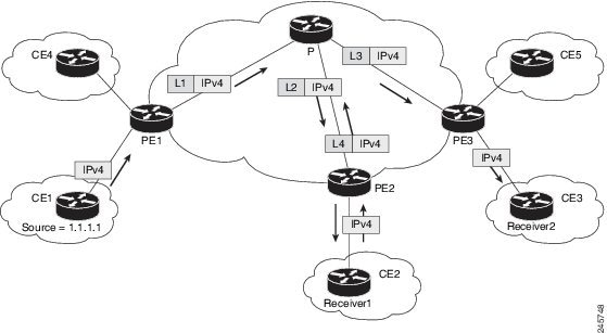


 Feedback