Configuring Pseudowire

This chapter provides information about configuring pseudowire (PW) features.

Pseudowire Overview

The following sections provide an overview of pseudowire.

Circuit Emulation Overview

Circuit Emulation (CEM) is a technology that provides a protocol-independent transport over IP networks. It enables proprietary or legacy applications to be carried transparently to the destination, similar to a leased line.

The Cisco router supports two pseudowire types that utilize CEM transport: Structure-Agnostic TDM over Packet (SAToP) and Circuit Emulation Service over Packet-Switched Network (CESoPSN). The following sections provide an overview of these pseudowire types.

Structure-Agnostic TDM over Packet

SAToP encapsulates time division multiplexing (TDM) bit-streams (T1, E1, T3, E3) as PWs over public switched networks. It disregards any structure that may be imposed on streams, in particular the structure imposed by the standard TDM framing.

The protocol used for emulation of these services does not depend on the method in which attachment circuits are delivered to the provider edge (PE) devices. For example, a T1 attachment circuit is treated the same way for all delivery methods, including copper, multiplex in a T3 circuit, a virtual tributary of a SONET/SDH circuit, or unstructured Circuit Emulation Service (CES).

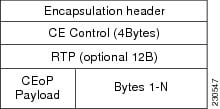
In SAToP mode the interface is considered as a continuous framed bit stream. The packetization of the stream is done according to IETF RFC 4553. All signaling is carried out transparently as a part of a bit stream. The figure below shows the frame format in Unstructured SAToP mode.

Figure 1. Unstructured SAToP Mode Frame Format

The table below shows the payload and jitter limits for the T1 lines in the SAToP frame format.

SAToP T1 Frame: Payload and Jitter Limits

Maximum Payload

Maximum Jitter

Minimum Jitter

Minimum Payload

Maximum Jitter

Minimum Jitter

960

32

10

192

64

2

The table below shows the payload and jitter limits for the E1 lines in the SAToP frame format.

SAToP E1 Frame: Payload and Jitter Limits

Maximum Payload

Maximum Jitter

Minimum Jitter

Minimum Payload

Maximum Jitter

Minimum Jitter

1280

32

10

256

64

2

For instructions on how to configure SAToP, see “Configuring Structure-Agnostic TDM over Packet” section on page 11-11.

Circuit Emulation Service over Packet-Switched Network

CESoPSN encapsulates structured TDM signals as PWs over public switched networks (PSNs). It complements similar work for structure-agnostic emulation of TDM bit streams, such as SAToP. Emulation of circuits saves PSN bandwidth and supports DS0-level grooming and distributed cross-connect applications. It also enhances resilience of CE devices due to the effects of loss of packets in the PSN.

CESoPSN identifies framing and sends only the payload, which can either be channelized T1s within DS3 or DS0s within T1. DS0s can be bundled to the same packet. The CESoPSN mode is based on IETF RFC 5086.

CESoPSN supports channel associated signaling (CAS) for E1 and T1 interfaces. CAS provides signaling information within each DS0 channel as opposed to using a separate signaling channel. CAS is also referred to as in-band signaling or robbed bit signaling.

Each supported interface can be configured individually to any supported mode. The supported services comply with IETF and ITU drafts and standards.

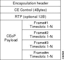
The figure below shows the frame format in CESoPSN mode.

Figure 2. Structured CESoPSN Mode Frame Format

The table below shows the payload and jitter for the DS0 lines in the CESoPSN mode.

CESoPSN DS0 Lines: Payload and Jitter Limits

DS0

Maximum Payload

Maximum Jitter

Minimum Jitter

Minimum Payload

Maximum Jitter

Minimum Jitter

1

40

32

10

32

256

8

2

80

32

10

32

128

4

3

120

32

10

33

128

4

4

160

32

10

32

64

2

5

200

32

10

40

64

2

6

240

32

10

48

64

2

7

280

32

10

56

64

2

8

320

32

10

64

64

2

9

360

32

10

72

64

2

10

400

32

10

80

64

2

11

440

32

10

88

64

2

12

480

32

10

96

64

2

13

520

32

10

104

64

2

14

560

32

10

112

64

2

15

600

32

10

120

64

2

16

640

32

10

128

64

2

17

680

32

10

136

64

2

18

720

32

10

144

64

2

19

760

32

10

152

64

2

20

800

32

10

160

64

2

21

840

32

10

168

64

2

22

880

32

10

176

64

2

23

920

32

10

184

64

2

24

960

32

10

192

64

2

25

1000

32

10

200

64

2

26

1040

32

10

208

64

2

27

1080

32

10

216

64

2

28

1120

32

10

224

64

2

29

1160

32

10

232

64

2

30

1200

32

10

240

64

2

31

1240

32

10

248

64

2

32

1280

32

10

256

64

2

Transportation of Service Using Ethernet over MPLS

Ethernet over MPLS (EoMPLS) PWs provide a tunneling mechanism for Ethernet traffic through an MPLS-enabled Layer 3 core network. EoMPLS PWs encapsulate Ethernet protocol data units (PDUs) inside MPLS packets and use label switching to forward them across an MPLS network. EoMPLS PWs are an evolutionary technology that allows you to migrate packet networks from legacy networks while providing transport for legacy applications. EoMPLS PWs also simplify provisioning, since the provider edge equipment only requires Layer 2 connectivity to the connected customer edge (CE) equipment. The Cisco router implementation of EoMPLS PWs is compliant with the RFC 4447 and 4448 standards.

The Cisco router supports VLAN rewriting on EoMPLS PWs. If the two networks use different VLAN IDs, the router rewrites PW packets using the appropriate VLAN number for the local network.

For instructions on how to create an EoMPLS PW, see . Configuring an Ethernet over MPLS Pseudowire.

CEM Configuration

This section provides information about how to configure CEM. CEM provides a bridge between a time-division multiplexing (TDM) network and a packet network, such as Multiprotocol Label Switching (MPLS). The router encapsulates the TDM data in the MPLS packets and sends the data over a CEM pseudowire to the remote provider edge (PE) router. Thus, function as a physical communication link across the packet network.

Configuration Guidelines and Restrictions

Not all combinations of payload size and dejitter buffer size are supported. If you apply an incompatible payload size or dejitter buffer size configuration, the router rejects it and reverts to the previous configuration.

Configuring a CEM Group

SUMMARY STEPS

  1. enable
  2. configure terminal
  3. controller {t1 | e1} slot/subslot/port
  4. cem-group group-number {unframed | timeslots timeslot }
  5. end

DETAILED STEPS

  Command or Action Purpose
Step 1

enable

Example:

Router> enable

Enables privileged EXEC mode.

  • Enter your password if prompted.

Step 2

configure terminal

Example:

Router# configure terminal

Enters global configuration mode.

Step 3

controller {t1 | e1} slot/subslot/port

Example:

Router(config)# controller t1 1/0

Enters controller configuration mode.

  • Use the slot and port arguments to specify the slot number and port number to be configured.

Note 

The slot number is always 0.

Step 4

cem-group group-number {unframed | timeslots timeslot }

Example:

Router(config-controller)# cem-group 6 timeslots 1-4,9,10

Creates a circuit emulation channel from one or more time slots of a T1 or E1 line.

  • The group-number keyword identifies the channel number to be used for this channel. For T1 ports, the range is 0 to 23. For E1 ports, the range is 0 to 30.

  • Use the unframed keyword to specify that a single CEM channel is being created including all time slots and the framing structure of the line.

  • Use the timeslots keyword and the timeslot argument to specify the time slots to be included in the CEM channel. The list of time slots may include commas and hyphens with no spaces between the numbers.

Step 5

end

Example:

Router(config-controller)# end 

Exits controller configuration mode and returns to privileged EXEC mode.

Using CEM Classes

A CEM class allows you to create a single configuration template for multiple CEM pseudowires. Follow these steps to configure a CEM class:


Note

The CEM parameters at the local and remote ends of a CEM circuit must match; otherwise, the pseudowire between the local and remote PE routers will not come up.


Note

You cannot apply a CEM class to other pseudowire types such as ATM over MPLS.


SUMMARY STEPS

  1. enable
  2. configure terminal
  3. class cem mycemclass
  4. payload-size 512
  5. dejitter-buffer 10
  6. idle-pattern 0x55
  7. exit
  8. interface cem 0/0
  9. no ip address
  10. cem 0
  11. cem class mycemclass
  12. xconnect 10.10.10.10 200 encapsulation mpls
  13. end

DETAILED STEPS

  Command or Action Purpose
Step 1

enable

Example:

Router> enable

Enables privileged EXEC mode.

  • Enter your password if prompted.

Step 2

configure terminal

Example:

Router# configure terminal

Enters global configuration mode.

Step 3

class cem mycemclass

Example:

Router(config)# class cem mycemclass

Creates a new CEM class

Step 4

payload-size 512

Example:

Router(config-cem-class)# payload-size 512

Enter the configuration commands common to the CEM class. This example specifies a sample rate and payload size.

Step 5

dejitter-buffer 10

Example:

Router(config-cem-class)# dejitter-buffer 10

This example specifies the dejitter buffer.

Step 6

idle-pattern 0x55

Example:

Router(config-cem-class)# idle-pattern 0x55

This example specifies the idle pattern.

Step 7

exit

Example:

Router(config-cem-class)# exit

Returns to the config prompt.

Step 8

interface cem 0/0

Example:

Router(config)# interface cem 0/0

Configure the CEM interface that you want to use for the new CEM class.

Step 9

no ip address

Example:

Router(config-if)# no ip address

Configure the CEM interface that you want to use for the new CEM class.

Step 10

cem 0

Example:

Router(config-if)# cem 0

Configure the CEM interface that you want to use for the new CEM class.

Step 11

cem class mycemclass

Example:

Router(config-if-cem)# cem class mycemclass

Configure the CEM interface that you want to use for the new CEM class.

Step 12

xconnect 10.10.10.10 200 encapsulation mpls

Example:

Router(config-if-cem)# xconnect 10.10.10.10 200 encapsulation mpls

Configure the CEM interface that you want to use for the new CEM class.

Note 

The use of the xconnect command can vary depending on the type of pseudowire you are configuring.

Step 13

end

Example:

Router(config-if-cem)# end

Exits the CEM interface.

CEM Parameters Configuration


Note

The CEM parameters at the local and remote ends of a CEM circuit must match; otherwise, the pseudowire between the local and remote PE routers will not come up.


Configuring Payload Size (Optional)

To specify the number of bytes encapsulated into a single IP packet, use the pay-load size command. The size argument specifies the number of bytes in the payload of each packet. The range is from 32 to 1312 bytes.

Default payload sizes for an unstructured CEM channel are as follows:

  • E1 = 256 bytes

  • T1 = 192 bytes

  • DS0 = 32 bytes

Default payload sizes for a structured CEM channel depend on the number of time slots that constitute the channel. Payload size (L in bytes), number of time slots (N), and packetization delay (D in milliseconds) have the following relationship: L = 8*N*D. The default payload size is selected in such a way that the packetization delay is always 1 millisecond. For example, a structured CEM channel of 16xDS0 has a default payload size of 128 bytes.

The payload size must be an integer of the multiple of the number of time slots for structured CEM channels.

Setting the Dejitter Buffer Size

To specify the size of the dejitter buffer used to compensate for the network filter, use the dejitter-buffer size command. The configured dejitter buffer size is converted from milliseconds to packets and rounded up to the next integral number of packets. Use the size argument to specify the size of the buffer, in milliseconds. The range is from 1 to 32 ms; the default is 5 ms.

Setting an Idle Pattern (Optional)

To specify an idle pattern, use the [no] idle-pattern pattern1 command. The payload of each lost CESoPSN data packet must be replaced with the equivalent amount of the replacement data. The range for pattern is from 0x0 to 0xFF; the default idle pattern is 0xFF.

Enabling Dummy Mode

Dummy mode enables a bit pattern for filling in for lost or corrupted frames. To enable dummy mode, use the dummy-mode [ last-frame | user-defined] command. The default is last-frame. The following is an example:


Router(config-cem)# dummy-mode last-frame

Setting a Dummy Pattern

If dummy mode is set to user-defined, you can use the dummy-pattern pattern command to configure the dummy pattern. The range for pattern is from 0x0 to 0xFF. The default dummy pattern is 0xFF. The following is an example:


Router(config-cem)# dummy-pattern 0x55

Shutting Down a CEM Channel

To shut down a CEM channel, use the shutdown command in CEM configuration mode. The shutdown command is supported only under CEM mode and not under the CEM class.

Configuring Structure-Agnostic TDM over Packet

SUMMARY STEPS

  1. enable
  2. configure terminal
  3. controller t1
  4. cem-group 4 unframed
  5. interface CEM0/4
  6. no ip address
  7. cem 4
  8. xconnect 30.30.30.2 304 encapsulation mpls
  9. exit

DETAILED STEPS

  Command or Action Purpose
Step 1

enable

Example:

Router> enable

Enables privileged EXEC mode.

Step 2

configure terminal

Example:

Router# configure terminal

Enters global configuration mode.

Step 3

controller t1

Example:

Router(config-controller)# controller t1

Configures the T1 or E1 interface.

Step 4

cem-group 4 unframed

Example:

Router(config-if)# cem-group 4 unframed

Assigns channels on the T1 or E1 circuit to the CEM channel. This example uses the unframed parameter to assign all the T1 timeslots to the CEM channel.

Step 5

interface CEM0/4

Example:

Router(config)# interface CEM0/4

Defines a CEM group.

Step 6

no ip address

Example:

Router(config-if)# no ip address

Defines a CEM group.

Step 7

cem 4

Example:

Router(config-if)# cem 4

Defines a CEM group.

Step 8

xconnect 30.30.30.2 304 encapsulation mpls

Example:

Router(config-if)# xconnect 30.30.30.2 304 encapsulation mpls

Binds an attachment circuit to the CEM interface to create a pseudowire. This example creates a pseudowire by binding the CEM circuit 304 to the remote peer 30.30.2.304.

Step 9

exit

Example:

Router(config)# exit

Exits configuration mode.

Note 

When creating IP routes for a pseudowire configuration, we recommend that you build a route from the xconnect address (LDP router-id or loopback address) to the next hop IP address, such as ip route 30.30.30.2 255.255.255.255 1.2.3.4

Configuring Circuit Emulation Service over Packet-Switched Network

Follow these steps to configure CESoPSN on the Cisco router.

SUMMARY STEPS

  1. Router> enable
  2. Router# configure terminal
  3. Router(config)# controller [e1|t1] 0/0
  4. Router(config-controller)# cem-group 5 timeslots 1-24
  5. Router(config-controller)# exit
  6. Router(config)# interface CEM0/5 Router(config-if-cem)# cem 5
  7. Router(config-if-cem)# xconnect 30.30.30.2 305 encapsulation mpls
  8. Router(config-if-cem)# exit

DETAILED STEPS

  Command or Action Purpose
Step 1

Router> enable

Enables privileged EXEC mode.

  • Enter your password if prompted.

Step 2

Router# configure terminal

Enters global configuration mode.

Step 3

Router(config)# controller [e1|t1] 0/0

Enters configuration mode for the E1 or T1 controller.

Step 4

Router(config-controller)# cem-group 5 timeslots 1-24

Assigns channels on the T1 or E1 circuit to the circuit emulation (CEM) channel. This example uses the timeslots parameter to assign specific timeslots to the CEM channel.

Step 5

Router(config-controller)# exit

Exits controller configuration.

Step 6

Router(config)# interface CEM0/5 Router(config-if-cem)# cem 5

Defines a CEM channel.

Step 7

Router(config-if-cem)# xconnect 30.30.30.2 305 encapsulation mpls

Binds an attachment circuit to the CEM interface to create a pseudowire. This example creates a pseudowire by binding the CEM circuit 5 to the remote peer 30.30.30.2.

Note 

When creating IP routes for a pseudowire configuration, we recommend that you build a route from the xconnect address (LDP router-id or loopback address) to the next hop IP address, such as ip route 30.30.30.2 255.255.255.255 1.2.3.4.

Step 8

Router(config-if-cem)# exit

Exits the CEM interface.

Configuring an Ethernet over MPLS Pseudowire

Ethernet over MPLS PWs allow you to transport Ethernet traffic over an existing MPLS network. The Cisco Router supports EoMPLS pseudowires on EVC interfaces.

For more information about Ethernet over MPLS Pseudowires, see the Transportation of Service Using Ethernet over MPLS chapter. For more information about how to configure MPLS, see the Cisco IOS XE 3S Configuration Guides. For more information about configuring Ethernet Virtual Connections (EVCs), see Cisco NCS 4200 Series Software Configuration Guide.

SUMMARY STEPS

  1. Router> enable
  2. Router# configure terminal
  3. Router(config)# interface gigabitethernet 0/0/4
  4. Router(config-if)#service instance 2 ethernet
  5. Router (config-if-srv)# encapsulation dot1q 2
  6. Router (config-if-srv)# xconnect 10.1.1.2 101 encapsulation mpls
  7. Router(config)# exit

DETAILED STEPS

  Command or Action Purpose
Step 1

Router> enable

Enables privileged EXEC mode.

  • Enter your password if prompted.

Step 2

Router# configure terminal

Enters global configuration mode.

Step 3

Router(config)# interface gigabitethernet 0/0/4

Specifies the port on which to create the pseudowire and enters interface configuration mode. Valid interfaces are physical Ethernet ports.

Step 4

Router(config-if)#service instance 2 ethernet

Configure an EFP (service instance) and enter service instance configuration) mode.

  • The number is the EFP identifier, an integer from 1 to 4000.

  • (Optional) ethernet name is the name of a previously configured EVC. You do not need to use an EVC name in a service instance.

Note 

You can use service instance settings such as encapsulation, dot1q, and rewrite to configure tagging properties for a specific traffic flow within a given pseudowire session. For more information, see Cisco NCS 4200 Series Software Configuration Guide .

Step 5

Router (config-if-srv)# encapsulation dot1q 2

Configure encapsulation type for the service instance.

  • default —Configure to match all unmatched packets.

  • dot1q —Configure 802.1Q encapsulation.

  • priority-tagged —Specify priority-tagged frames, VLAN-ID 0 and CoS value of 0 to 7.

  • untagged —Map to untagged VLANs. Only one EFP per port can have untagged encapsulation.

Step 6

Router (config-if-srv)# xconnect 10.1.1.2 101 encapsulation mpls

Binds the Ethernet port interface to an attachment circuit to create a pseudowire. This example uses virtual circuit (VC) 101 to uniquely identify the PW. Ensure that the remote VLAN is configured with the same VC.

Note 

When creating IP routes for a pseudowire configuration, we recommend that you build a route from the xconnect address (LDP router-id or loopback address) to the next hop IP address, such as ip route 10.30.30.2 255.255.255.255 10.2.3.4 .

Step 7

Router(config)# exit

Exits configuration mode.

Verifying the Interface Configuration

You can use the following commands to verify your pseudowire configuration:

  • show cem circuit —Displays information about the circuit state, administrative state, the CEM ID of the circuit, and the interface on which it is configured. If xconnect is configured under the circuit, the command output also includes information about the attached circuit.

    
    Router# show cem circuit ? 
      <0-504>    CEM ID
      detail     Detailed information of cem ckt(s)
      interface  CEM Interface
      summary    Display summary of CEM ckts
      |          Output modifiers
    
    
    Router# show cem circuit 
    CEM Int.       ID   Line      Admin     Circuit         AC
    --------------------------------------------------------------
    CEM0/1/0       1    UP        UP        ACTIVE          --/--
    CEM0/1/0       2    UP        UP        ACTIVE          --/--
    CEM0/1/0       3    UP        UP        ACTIVE          --/--
    CEM0/1/0       4    UP        UP        ACTIVE          --/--
    CEM0/1/0       5    UP        UP        ACTIVE          --/--
    
  • show cem circuit—D isplays the detailed information about that particular circuit.

    
    Router# show cem circuit 1 
    CEM0/1/0, ID: 1, Line State: UP, Admin State: UP, Ckt State: ACTIVE
    Idle Pattern: 0xFF, Idle cas: 0x8, Dummy Pattern: 0xFF
    Dejitter: 5, Payload Size: 40
    Framing: Framed, (DS0 channels: 1-5)
    Channel speed: 56
    CEM Defects Set
    Excessive Pkt Loss RatePacket Loss
    
    Signalling: No CAS
    Ingress Pkts:    25929                Dropped:             0
    Egress Pkts:     0                    Dropped:             0
    CEM Counter Details
    Input Errors:    0                    Output Errors:       0
    Pkts Missing:    25927                Pkts Reordered:      0
    Misorder Drops:  0                    JitterBuf Underrun:  1
    Error Sec:       26                   Severly Errored Sec: 26
    Unavailable Sec: 5                    Failure Counts:      1
    Pkts Malformed:  0
    
  • show cem circuit summary —Displays the number of circuits which are up or down per interface basis.

    
    Router# show cem circuit summary
    CEM Int.       Total Active  Inactive
    --------------------------------------
    CEM0/1/0       5     5       0
    

show running configuration —The show running configuration command shows detail on each CEM group.

Configuration Examples

The following sections contain sample pseudowire configurations.

Example: CEM Configuration

The following example shows how to add a T1 interface to a CEM group as a part of a SAToP pseudowire configuration. For more information about how to configure pseudowires, see the Pseudowire Configuration chapter.


Note

This section displays a partial configuration intended to demonstrate a specific feature.


controller T1 0/0/0
 framing unframed
 clock source internal
 linecode b8zs
 cablelength short 110
 cem-group 0 unframed

interface CEM0/0/0
 no ip address
 cem 0
  xconnect 18.1.1.1 1000 encapsulation mpls

Example: Ethernet over MPLS

PE 1 Configuration


!
mpls label range 16 12000 static 12001 16000
mpls label protocol ldp
mpls ldp neighbor 10.1.1.1 targeted ldp
mpls ldp graceful-restart
multilink bundle-name authenticated
!
!
!
!
redundancy
 mode sso
!
!
!
ip tftp source-interface GigabitEthernet0
!
!
interface Loopback0
 ip address 10.5.5.5 255.255.255.255

!
interface GigabitEthernet0/0/4
 no ip address
 negotiation auto
!
 service instance 2 ethernet
  encapsulation dot1q 2
  xconnect 10.1.1.1 1001 encapsulation mpls
 !
 service instance 3 ethernet
  encapsulation dot1q 3
  xconnect 10.1.1.1 1002 encapsulation mpls
 !
!
interface GigabitEthernet0/0/5
 ip address 172.7.7.77 255.0.0.0
 negotiation auto
 mpls ip
 mpls label protocol ldp
!
router ospf 1
 router-id 5.5.5.5
 network 5.5.5.5 0.0.0.0 area 0
 network 172.0.0.0 0.255.255.255 area 0
 network 10.33.33.33 0.0.0.0 area 0
 network 192.0.0.0 0.255.255.255 area 0
!

PE 2 Configuration


!
mpls label range 16 12000 static 12001 16000
mpls label protocol ldp
mpls ldp neighbor 10.5.5.5 targeted ldp
mpls ldp graceful-restart
multilink bundle-name authenticated
!
!
redundancy
 mode sso
!
!
!
ip tftp source-interface GigabitEthernet0
!
!
interface Loopback0
 ip address 10.1.1.1 255.255.255.255

!
interface GigabitEthernet0/0/4
 no ip address
 negotiation auto
!
 service instance 2 ethernet
  encapsulation dot1q 2
  xconnect 10.5.5.5 1001 encapsulation mpls
 !
 service instance 3 ethernet
  encapsulation dot1q 3
  xconnect 10.5.5.5 1002 encapsulation mpls
 !
!
interface GigabitEthernet0/0/5
 ip address 172.7.7.7 255.0.0.0
 negotiation auto
 mpls ip
 mpls label protocol ldp
!
router ospf 1
 router-id 10.1.1.1
 network 10.1.1.1 0.0.0.0 area 0
 network 172.0.0.0 0.255.255.255 area 0
 network 10.33.33.33 0.0.0.0 area 0
 network 192.0.0.0 0.255.255.255 area 0
!