Platform Specific Configurations

ENCS Switch Configuration

Access to the ENCS switch is restricted through Consent Token. Consent Token is a security feature that is used to authenticate the network administrator of an organization to access system shell with mutual consent from the network administrator and Cisco Technical Assistance Centre (Cisco TAC).


Note


  • From the switch console, there is access to debug mode and an advanced debug mode. Credentials of the local user are synchronized to access debug mode. Advanced debug uses unique credentials for each device that allows for additional debugging options for Cisco engineering. To enter either debug mode permission must be granted through Consent Token.

  • To configure any parameter on the ENCS switch portal, ensure that you add or remove parameters using separate transactions on the CLI. For example, adding and removing multiple VLANs from the ENCS switch portal is not supported in the same CLI transaction. Add a VLAN first and then remove the VLAN in a separate transaction.


ENCS Switch Portal Configuration

Switch Settings

The Switch option from the Cisco Enterprise NFVIS portal allows you to configure STP/RSTP, VLAN on specified ranges, RADIUS based authentication, and port channel load balancing for various switch ports. This section describes how to configure settings on the ENCS switch portal.

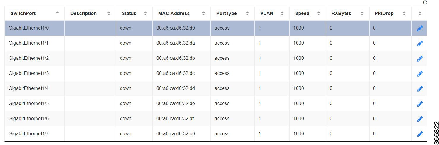
You can view the Switch Interface operational data and the statistics parameters in the following table:

Table 1. Switch Settings Interface

Parameter

Description

Values

SwitchPort

Specifies the switch interface name.

Description

Specifies the description of the interface.

Status

Specifies the status of the interface.

up or down

MAC Address

Specifies the MAC address of the interface.

PortType

Specifies the mode of the port interface.

Supported types are:

  • access

  • dot1q-tunnel

  • private-vlan

  • trunk

VLAN

Specifies the VLAN ID.

Range: 1-2349 and 2450-4093

Speed

Specifies the speed of the interface.

Speed:

  • 10 MBPS

  • 100 MBPS

  • 1000 MBPS

RxBytes

Specifies the received data on interface in bytes.

PktDrop

Specifies the number of packet drops.
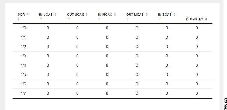
PORT

Specifies the port number.

IN-UCAST

Specifies the number of incoming unicast packets at the interface.

OUT-UCAST

Specifies the number of outgoing unicast packets at the interface.

IN-MCAST

Specifies the number of incoming multicast packets at the interface.

OUT-MCAST

Specifies the number of outgoing multicast packets at the interface.

IN-BCAST

Specifies the number of incoming broadcast packets at the interface.

OUT-BCAST

Specifies the number of outgoing broadcast packets at the interface.

Configuring Spanning Tree

Spanning Tree Protocol (STP) is a Layer 2 protocol that runs on bridges and switches. The main purpose of STP is to ensure that you do not create loops when you have redundant paths in your network.

The Spanning Tree option is enabled by default. You can click on edit and make the necessary settings or disable Spanning Tree if required.

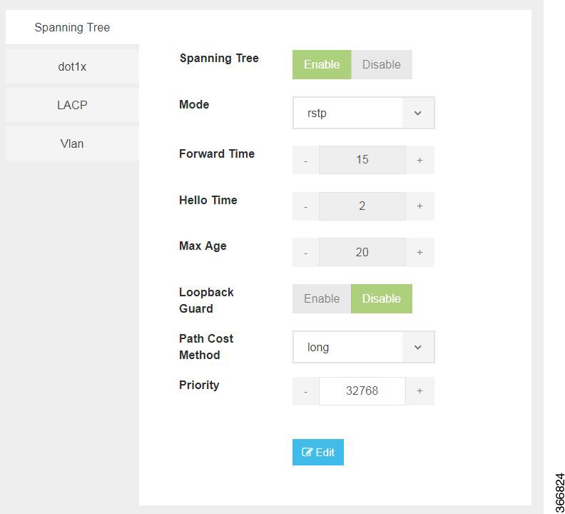
The configuration of spanning tree has the following parameters when it is enabled:

Table 2. Spanning Tree Parameters

Parameter

Description

Values

Spanning Tree

Specifies the state of the Spanning Tree.

Enable or Disable

The default value is Enable.

Mode

Specifies the mode of the Spanning Tree.

stp or rstp

Forward Time

Specifies the Spanning Tree forward time in seconds.

Range: 4-30 seconds

Hello Time

Specifies the Hello time in seconds.

Range: 1 to10 seconds

Max Age

Specifies the spanning-tree bridge maximum age in seconds.

Range: 6 to 40 seconds

Loopback Guard

Specifies the loopback guard status.

Enable or Disable

Path Cost Method

Specifies the speed of the interface.

Method:

  • long - for 32 bit based values for default port path costs.

  • short - 16 bit based values for default port path costs.

The default method is long.

Priority

Specifies the port priority.

Range: 0 to 61440 in steps of 4096

The default value is 32768.
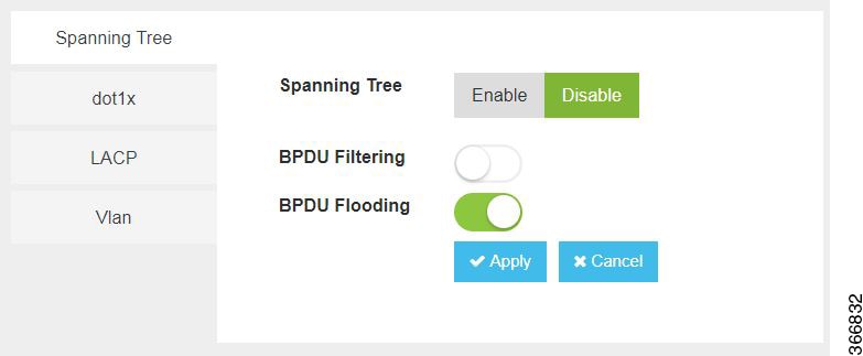
BPDU Filtering

Specifies that BPDU packets are filtered when the spanning tree is disabled on an interface.

BPDU Flooding

Specifies that BPDU packets are flooded unconditionally when the spanning tree is disabled on an interface.

Configuring Dot1x

This chapter describes how to configure dot1x port-based authentication on the Cisco Enterprise NFVIS portal. dot1x prevents unauthorized devices (clients) from gaining access to the network. It is a standard for media-level (Layer 2) access control, offering the capability to permit or deny network connectivity based on the identity of the end user or device. The dot1x is disabled by default. You can click on edit to enable dot1x.

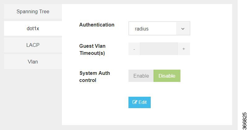
The configuration of dot1x has the following parameters:

Table 3. Dot1x Parameters

Parameter

Description

Values

Authentication

Specifies the authentication type for the port.

radius or none

The default value is radius.

Guest VLAN Timeout(s)

Specifies the time delay in seconds between enabling Dot1X (or port up) and adding the port to the guest VLAN.

Range: 30 to 180 seconds

System Auth control

Specifies the authentication control.

Enable or Disable

Configuring LACP

The Link Aggregation Control Protocol (LACP) enables you to bundle several physical ports together to form a single logical channel. LACP enables you to form a single Layer 2 link automatically from two or more Ethernet links. This protocol ensures that both ends of the Ethernet link are functional and are part of the aggregation group.

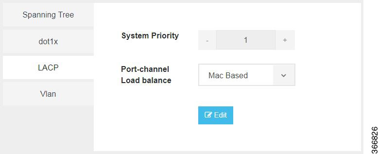
LACP uses the following parameters to control aggregation:

Table 4. LACP Parameters

Parameter

Description

Values

System Priority

Specifies the port priority.

Range: 1 to 65535

Port-channel load balance

Specifies the load balance of the port channel.

Mac Based or IP Based
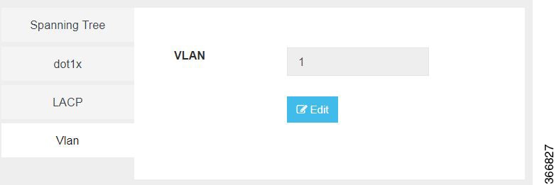
Configuring VLAN

You can use virtual LANs (VLANs) to divide the network into separate logical areas. VLANs can also be considered as broadcast domains. Any switch port can belong to a VLAN, and unicast, broadcast, and multicast packets are forwarded and flooded only to end stations in that VLAN. Each VLAN is considered a logical network, and packets destined for stations that do not belong to the VLAN must be forwarded through a router.

You can configure VLANs in the range <1-2349>|<2450-4093> for a specified switch port.


Note


  • When you use multiple Virtual Network Inteface Cards (VNICs) in your VLAN, ensure that each of the VNICs are configured within the VLAN network.

  • The Cisco ENCS hardware switch is typically connected to the Open vSwitch (OVS) using physical connections (like Ethernet cables) which are then represented as ports within the Open vSwitch configuration. When a VLAN is set up on the Cisco ENCS switch, perform the corresponding configuration on the OVS as well. Assign a VLAN tag to the OVS port that corresponds to the hardware switch port.

  • Use native VLANs for untagged traffic. If a hardware switch port is configured to use a certain VLAN as native, corresponding OVS port should also be configured to tag the untagged incoming traffic with the same VLAN. Allowed VLAN lists define which VLANs are allowed on a port.

  • While a hardware switch and OVS are logically connected, configurations do not automatically propagate between the two. Manually configure the both to ensure consistency and correct networking behavior.


Configuring General Settings

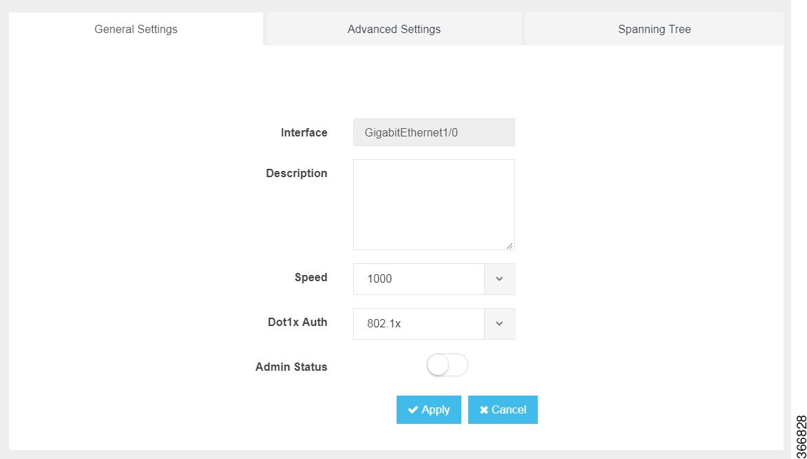
You can configure general settings using the following parameters for each switch interface:

  • Interface—Name of the interface

  • Description—Set the description per interface

  • Speed—10/100/1000 MBPS

  • Dot1x Auth—802.1x, mac or both

  • PoE Method—auto, never or four-pair

  • PoE Limit—0-60000mW

  • Admin Status—enable or disable

Configuring Advanced Settings

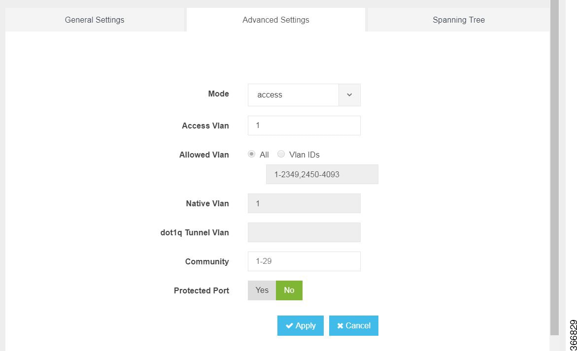
You can make the advanced settings using the following parameters for each switch interface:

  • Mode—access, dot1q-tunnel, private-vlan, or trunk

  • Access Vlan—Specifies the number of VLANs.

  • Allowed Vlan—All or VLAN IDs

  • Native Vlan—Specifies the VLAN ID. You can enter a value from one of the following ranges:

    • 1 to 2349

    • 2450 to 4093

  • Dot1q Tunnel Vlan—Specifies the Layer 2 tunnel port.

  • Community—Specifies the community number. Range: 1 to 29

  • Protected Port—Yes or No


Note


The VLAN configuration takes effect only if the global VLANs are also configured with the same values in Configuring VLAN.


Configuring Spanning Tree per Interface

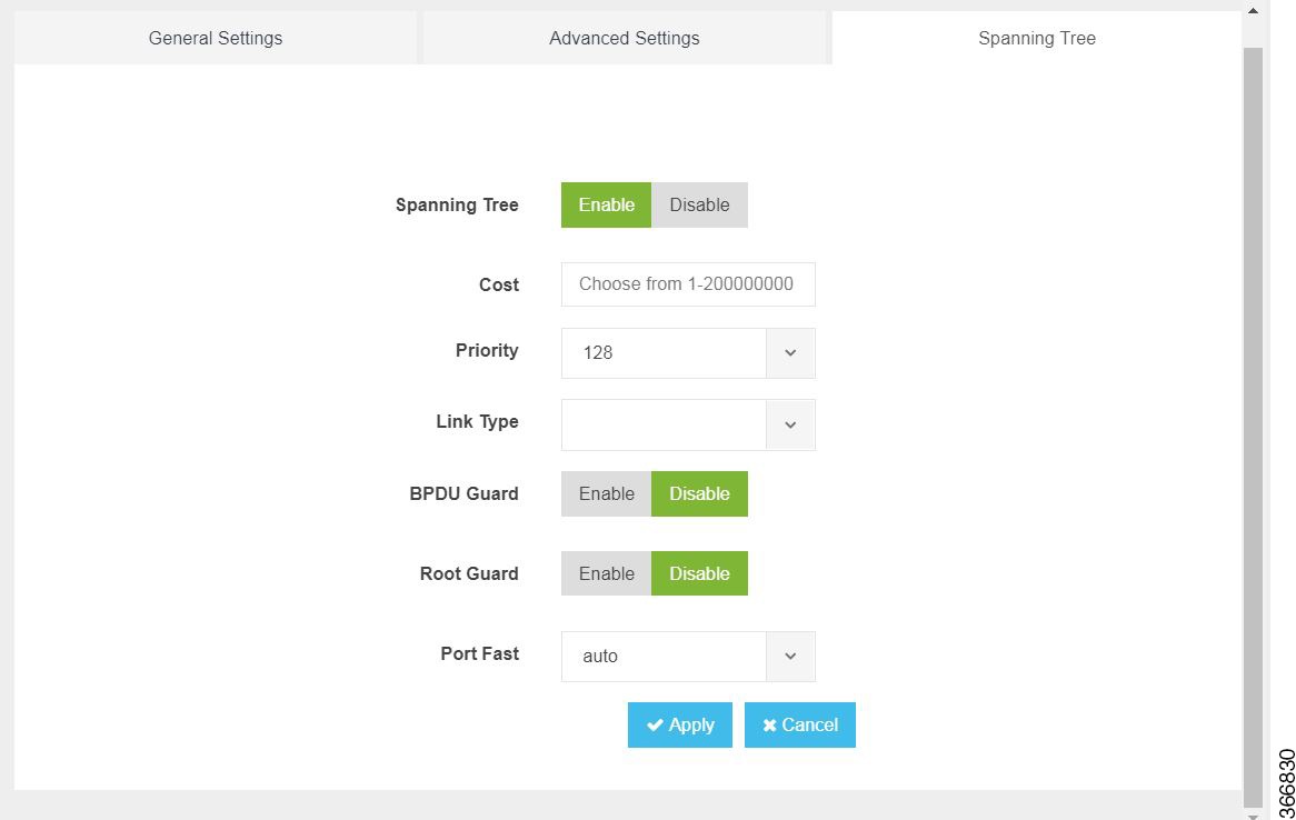
You can configure spanning tree for each switch interface using the following parameters:

  • Spanning Tree—Enable or Disable

  • Cost—Specifies the cost. Range: 1 to 200000000

  • Priority—Specifies the port priority. Range: 0 to 240, default value is 128

  • Link Type—point-to-point or shared

  • BPDU Guard—Enable or Disable

  • Root Guard—Enable or Disable

  • Port Fast—auto or enable

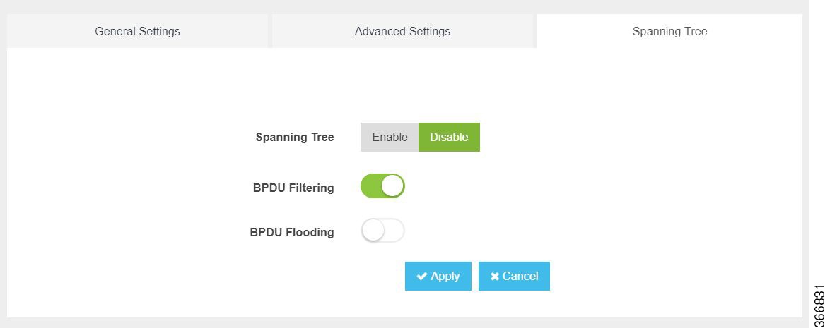
  • BPDU Filtering—Specifies that BPDU packets are filtered when the spanning tree is disabled

  • BPDU Flooding—Specifies that BPDU packets are flooded when the spanning tree is disabled

Configure Storm Control

Storm control is used to monitor incoming traffic levels and limit excessive flow of packets on any user facing switch port that could cause a traffic storm. Traffic storms can lead to device instability and unintended behavior.

You can configure storm control from Cisco NFVIS Portal, from Storm Control tab.

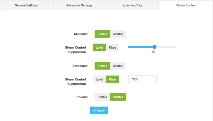
Storm control can be configured for specific type of traffic - unicast or multicast or broadcast. The suppression range can be in terms of a percentage level (1-100) or Kbps value (1-1000000).

Configure Additional WAN Transport Connectivity On ENCS Switch Ports

Table 5. Feature History

Feature Name

Release Information

Description

Configure Additional WAN Transport Connectivity On ENCS Switch Ports

NFVIS Release 4.10

This feature enables configuring additional Transport Locator (TLOC) an attachment point. The attachment point is where a Cisco WAN Edge device connects to a WAN transport using ENCS LAN ports as WAN ports. This is in addition to the currently available WAN connectivity options that is restricted to just two WAN ports.

Starting from NFVIS Release 4.10, map LAN SR-IOV (Single Root Input or Output Virtualization) with Cisco ISRv or Cisco Catalyst 8000V to configure additonal WAN transport connectivity on ENCS switch ports. The following are the changes to ENCS LAN and WAN ports connectivity:

  • The WAN circuit TLOC terminates on layer 3 ports (GE0-0 or GE0-1).

  • The WAN circuit TLOC physically connects to any switch port (GE1/0 - GE1/7).

  • The LAN traffic flows through the switchports (GE1/0 - GE1/7).


Note


Cisco Security Group Tag (SGT) is added to the LAN interfaces which are propagated to all the TLOCs that are handled by VNFs such as Cisco ISRv or Cisco Catalyst 8000V. For more information see, Cisco TrustSec Integration.


Prerequisites to Configure Additional WAN Transport Connectivity On ENCS Switch Ports

Setup Cisco ISRv or Cisco Catalyst 8000V devices using Cisco NFVIS.

Configure Additional WAN Transport Connectivity Using MPLS

This section provides an example configuration to configure additional WAN ports on ENCS switch ports with ISRv and Catalyst 8000V using MPLS:

  1. Enter the configuration mode:

    config-transaction
  2. Enter the sdwan mode:

    sdwan
  3. Configure the interface into a tunnel interface:

    tunnel interface
  4. Configure an interface type and enter the interface configuration mode:

    interface GigabitEthernet2
  5. Configure an encapsulation for a tunnel interface:

    encapsulation ipsec
  6. Assign a color to a WAN transport tunnel:

    color mpls
  7. Configure the services that are allowed on a tunnel interface:

    
    allow-service all
    no allow-service bgp
    allow-service dhcp
    allow-service dns
    allow-service icmp
    no allow-service sshd
    no allow-service netconf
    allow-service ntp
    no allow-service ospf
    no allow-service stun
    allow-service https
    no allow-service snmp
    no allow-service bfd

Here's the complete configuration example for configuring additional WAN ports on ENCS switch ports with ISRv and Catalyst 8000V using MPLS:

sdwan
interface GigabitEthernet2
tunnel-interface
encapsulation ipsec
color mpls
max-control-connections 0
allow-service all
no allow-service bgp
allow-service dhcp
allow-service dns
allow-service icmp
no allow-service sshd
no allow-service netconf
allow-service ntp
no allow-service ospf
no allow-service stun
allow-service https
no allow-service snmp
no allow-service bfd
!

Configure Additional WAN Transport Connectivity Using Biz Internet

This section provides an example configuration to configure additional WAN ports on ENCS switch ports with ISRv and Catalyst 8000V using biz internet:

  1. Enter the configuration mode:

    config-transaction
  2. Enter the sdwan mode:

    sdwan
  3. Configure the interface into a tunnel interface:

    tunnel interface
  4. Configure an interface type and enter the interface configuration mode:

    interface GigabitEthernet5.101
  5. Configure an encapsulation for a tunnel interface:

    encapsulation ipsec
  6. Restrict the biz internet colors:

    color biz internet restrict
  7. Configure the services that are allowed on a tunnel interface:

    
    no allow-service bgp
    allow-service dhcp
    allow-service dns
    allow-service icmp
    no allow-service sshd
    no allow-service netconf
    no allow-service ntp
    no allow-service ospf
    no allow-service stun
    allow-service https
    no allow-service snmp
    no allow-service bfd

Here's the complete configuration example for configuring additional WAN ports on ENCS switch ports with ISRv and Catalyst 8000V using biz internet:

sdwan
interface GigabitEthernet5.101
tunnel-interface
encapsulation ipsec
color biz-internet restrict
no allow-service bgp
allow-service dhcp
allow-service dns
allow-service icmp
no allow-service sshd
no allow-service netconf
no allow-service ntp
no allow-service ospf
no allow-service stun
allow-service https
no allow-service snmp
no allow-service bfd
!

Configure Additional WAN Transport Connectivity Using Public Internet

This section provides an example configuration to configure additional WAN ports on ENCS switch ports with ISRv and using public internet:

  1. Enter the configuration mode:

    config-transaction
  2. Enter the sdwan mode:

    sdwan
  3. Configure the interface into a tunnel interface:

    tunnel interface
  4. Configure an interface type and enter the interface configuration mode:

    interface GigabitEthernet6
  5. Configure an encapsulation for a tunnel interface:

    encapsulation ipsec
  6. Restrict the public internet colors:

    color public internet restrict
  7. Configure the services that are allowed on a tunnel interface:

    
    no allow-service bgp
    allow-service dhcp
    allow-service dns
    allow-service icmp
    no allow-service sshd
    no allow-service netconf
    allow-service ntp
    no allow-service ospf
    no allow-service stun
    allow-service https
    no allow-service snmp
    no allow-service bfd

Here's the complete configuration example for configuring additional WAN ports on ENCS switch ports with ISRv and Catalyst 8000V using public internet:

sdwan
interface GigabitEthernet6
tunnel-interface
encapsulation ipsec
color public-internet restrict
no allow-service bgp
allow-service dhcp
allow-service dns
allow-service icmp
no allow-service sshd
no allow-service netconf
allow-service ntp
no allow-service ospf
no allow-service stun
allow-service https
no allow-service snmp
no allow-service bfd
!

Configuration Example of Additional WAN Transport Connectivity to Cisco ISRv or Catalyst 8000V

The following example shows the interfaces mapped to Cisco ISRv or Cisco Catalyst 8000V VM:

Name: S200-CE1
Deployment Name : S200-CE1
VM Group Name : S200-CE1
State: ALIVE
Internal State: VM_ALIVE_STATE
Bootup Time: 600
Image: isrv-universalk9.17.03.03.tar.gz
Flavor: ISRv-medium

VCPU# Memory(MB) Disk(MB)
----------------------------
4 4096 8192

Low Latency: true
VCPU CPU CORE SOCKET
-----------------------
0 2 2 0 
1 3 3 0 
2 4 4 0 
3 5 5 0

NICID VNIC NETWORK IP MAC-ADDRESS MODEL PORT-FORWARD 
---------------------------------------------------------------------------------------
0 vnic0 int-mgmt-net 10.20.0.2 52:54:00:cf:41:cc virtio  <----- Internal Monitoring
1 vnic1 LAN-SRIOV-20 - 52:54:00:90:3b:8c None <---- connects to GE1/0 for TLOC MPLS
2 vnic2 LAN-SRIOV-21 - 52:54:00:8a:c1:a1 None <---- host on LAN (service VPN/VRF)
3 vnic3 LAN-SRIOV-22 - 52:54:00:9c:17:db None <---- host on LAN (service VPN/VRF)
4 vnic4 LAN-SRIOV-23 - 52:54:00:f6:12:eb None <---- connects to GE1/6 for TLOC Biz-Internet
5 vnic5 GE0-0-SRIOV-1 - 52:54:00:e8:19:74 None <---- connects to GE0-0 for TLOC Public-Internet
6 vnic6 GE0-1-SRIOV-1 - 52:54:00:53:d4:d7 None <------ unused

Verify Mapping of LAN SR-IOV with Cisco ISRv or Cisco Catalyst 8000V Using Cisco ISRv or Cisco Catalyst 8000V CLI

The following is a sample output from the show sdwan control connections command:

router# show sdwan control connections
PEER PEER CONTROLLER 
PEER PEER PEER SITE DOMAIN PEER PRIV PEER PUB GROUP 
TYPE PROT SYSTEM IP ID ID PRIVATE IP PORT PUBLIC IP PORT LOCAL COLOR PROXY STATE UPTIME ID 
----------------------------------------------------------------------------------------------------------------------------------------------------------------------------------------
vsmart dtls 10.0.0.201 10000 1 192.10.10.200 12446 192.10.10.200 12446 public-internet No up 19:00:27:09 0 
vbond dtls 0.0.0.0 0 0 10.10.0.3 12346 10.10.0.3 12346 biz-internet - connect 0 
vbond dtls 0.0.0.0 0 0 10.10.0.3 12346 10.10.0.3 12346 public-internet - up 19:00:27:09 0 
vmanage dtls 10.0.0.101 10000 0 192.10.10.100 12446 192.10.10.100 12446 public-internet No up 19:00:27:09 0

Configuring vBranch High Availability

High availability design provides redundancy for WAN, LAN, ENCS device, vRouter, vFirewall VNF level redundancy.

A branch site can have two routers for redundancy. If vEdge-cloud router is chosen, Each of the vedge-cloud router maintains:

  • A secure control plane connection, via a DTLS connection, with each vSmart controller in its domain

  • A secure data plane connection with the other vEdge routers at the site

Because both vEdge routers receive the same routing information from the vSmart controllers, each one is able to continue to route traffic if one should fail, even if they are connected to different transport providers.

Two firewalls are placed in a group and their configuration is synchronized to prevent a single point of failure on your network. A heartbeat connection between the firewall peers ensures seamless failover in the event that a peer goes down. Setting up two firewalls in an HA pair provides redundancy and allows you to ensure business continuity.

Prerequisites for vBranch HA

The WAN links are active on both Cisco ENCS1 and Cisco ENCS2. Each of the ENCS WAN link is connected to the WAN network (most cases with two SPs), with two ENCSs in an active-active mode.

The LAN facing links of both Cisco ENCS devices are connected to an external switch (as an uplink), and all the devices on the LAN segment are also connected to the external switch. There should be no LAN device connecting directly to the Cisco ENCS internal switch.

Two vRouters and the Two vFirewalls have full mesh L3 connectivity.

VMs and VNFs on both ENCS devices must be configured identical.

SD-Branch HA Design and Topology

In HA design, there are two sets of VLANs. Traffic path is between the VNFs and traffic from or towards LAN.

To protect against cable connection issue and box failure, there is back-to-back cable between ENCS and connection from each ENCS to the external switch.

When using Cisco ENCS and Cisco switches, common expectation is to use PVST+, detect loops and switch specific ports to BLOCKING mode. ENCS switch does not support PVST (Per VLAN spanning tree). By Default, RSTP could end up blocking ENCS port back-to-back connection, this will result in blocking traffic path between the VNFs.

The recommended solution is to use MSTP in ENCS and the external switches. The following topology and configuration provides a step-by-step procedure with reasoning for specific configuration use. There are two instances of MSTP created. One for handling traffic path between VNFs and the second for handling traffic from or towards LAN.


Note


In cases where external switch cannot be configured for MSTP, RSTP is used and the two links back-2-back between ENCS is not in port-channel.

  • One of the links carries traffic between VNFs by configuring disable spanning tree. The second back-to-back link between ENCS processes RSTP and forward or block for the traffic from or towards LAN.

  • From each of the ENCS, a third physical link connects to the external switch. This also forwards or blocks the traffic from or towards LAN depending on the RSTP decisions.


Physical Device Connections

VM and Service Chain Network Connection

Figure 1. ENCS-Left
Figure 2. ENCS-Right

Note


In the absence of firewall in the design, the router is directly connected to the LAN side. Pt-to-Pt network extends the TLOC connection across the ENCS devices and VRRP is enabled in the router LAN facing connection.


Isolating LAN and Transit Link Traffic for vBranch HA

Traffic from or towards LAN and traffic between the VNFs are isolated by configuring different VLANs for each traffic since both links are connected to the same ENCS internal switch. If you do not isolate the traffic, both LAN traffic and transit link will flow through the same internal switch on the Cisco ENCS.

Enable Port Tracking and Virtual NIC Update

The configured VNICs tracks the state of the ports based on the PNICs notifications. To verify the state of the port, use show interface or ethtool commands. You can also use commands specific to the VM, that displays the interface link state.

To configure track state on GE0-0 & GE0-1:


configure terminal
pnic GE0-0 track-state ROUTER 1
end

ENCS-Left# support show ifconfig GE0-0

GE0-0: flags=4611<UP,BROADCAST,ALLMULTI,MULTICAST>  mtu 9216
        ether 70:db:98:c3:df:28  txqueuelen 1000  (Ethernet)

To configure track state on switch port:


configure terminal
switch interface gigabitEthernet 1/3 track-state FIREWALL 4
end

ENCS-Left# show vm_lifecycle deployments FIREWALL


Name: FIREWALL
Deployment Name : FIREWALL
VM Group Name : FIREWALL
State: ALIVE
Internal State: VM_INERT_STATE
Bootup Time: -1
Image: Palo-Alto-8.1.3.tar.gz
Flavor: VM-100


VCPU#  Memory(MB)  Disk(MB)
----------------------------
2      7168        61440


Low Latency: true
VCPU  CPU  CORE  SOCKET
-----------------------
0     3      3     0
1     2      2     0


NICID  VNIC   NETWORK  IP   MAC-ADDRESS        MODEL    PORT-FORWARD
-----------------------------------------------------------------------------
0      vnic6  mgmt-net -    52:54:00:2b:72:d2  virtio
1      vnic7  Untrust  -    52:54:00:eb:a3:e7  virtio
2      vnic8  HA1      -    52:54:00:f4:de:e5  virtio
3      vnic9  HA2      -    52:54:00:12:f8:21  virtio
4      vnic10  Trust    -    52:54:00:7a:6b:e9  virtio


ENCS-Left# support show ifconfig vnic10

vnic10: flags=4163<UP,BROADCAST,RUNNING,MULTICAST>  mtu 9216
        inet6 fe80::fc54:ff:fe7a:6be9  prefixlen 64  scopeid 0x20<link>
        ether fe:54:00:7a:6b:e9  txqueuelen 4000  (Ethernet)

Packet Flow for SD-Branch HA

This section explains high-level packet flow in non-failure and failure cases.

Non-Failure Case

In the non-failure case, both ENCS devices are Active, up and running

  • LAN to WAN through the ENCS1 Firewall and ENCS1 Router

  • LAN to WAN through the ENCS1 Firewall and ENCS2 Router

  • WAN to LAN through ENCS1 Router and ENCS1 Firewall

  • WAN to LAN through ENCS2 Router and ENCS1 Firewall

Failure Case

Following are failures that a router must be designed and configured to adapt

The conditions that trigger a firewall failover are:

  • One or more of the monitored interfaces fail. (Link Monitoring)

  • One or more of the destinations specified on the firewall cannot be reached. (Path Monitoring)

  • The firewall does not respond to heartbeat polls. (Heartbeat Polling and Hello messages)

Configuration Examples and Usage Description

ENCS-Left and ENCS-Right with Same Config

Description or Reasons for configuration


networks network wan-net
 bridge wan-br
!
networks network HA1
 vlan   [ 126 ]
 trunk  false
 bridge lan-br
!
networks network HA2
 vlan   [ 127 ]
 trunk  false
 bridge lan-br
!
networks network Trust
 vlan   [ 128 ]
 bridge lan-br
!
networks network Untrust
 vlan   [ 998 ]
 bridge lan-br
!
networks network mgmt-net
 vlan   [ 100 ]
 trunk  false
 bridge lan-br
!
networks network pt-2-pt
 vlan   [ 996 997 ]
 bridge lan-br

In a HA design involving a router or Firewall, there are 3 to 6 paths required. ENCS platform has 2 WAN facing ports and 8 LAN facing ports.

  • WAN facing ports are reserved for connection to WAN circuits.

  • LAN facing ports are the only set of available ports for creating the 3 to 6 path required.

Between VNFs and LAN, OVS or SR-IOV VFs and physical switch ports are the two Layer2 entities to traverse.


!
 vlan 1
!
 vlan 100
 !
 vlan 126
 !
 vlan 127
 !
 vlan 128
 !
 vlan 996
 !
 vlan 997
 !
 vlan 998
 !
 spanning-tree enable
 spanning-tree mode mst
 spanning-tree mst 2 priority 61440
 spanning-tree mst configuration
  name mst_LAN
  instance 1 vlan 996-998
  instance 2 vlan 100,126-128
!

VLAN must be explicitly created before they are used in the interfaces.

Enable MSTP. For MST group 2 carrying “Traffic towards/from LAN”, force the External Switch to become the ROOT using the “mst <group> priority <value>” CLI. The Higher the value, lower the chance of becoming spanning-tree ROOT.

“priority” configuration is NOT required for the MST group 1 carrying “Traffic between VNFs”. There is NO loop possibility for MST group 1 VLANs.


nfvis# show running-config switch
switch
interface gigabitEthernet1/1
  no shutdown
  channel-group 1 mode auto
 !
 interface gigabitEthernet1/2
  no shutdown
  channel-group 1 mode auto
!
switch
 interface port-channel1
  negotiation auto
  no shutdown
  spanning-tree mst 1 cost 200000000
  spanning-tree mst 2 cost 200000000
  switchport mode trunk
  switchport trunk native vlan 1
  switchport trunk allowed vlan 100,126-128,996-998
 !

For the back-to-back ENCS connection, link redundancy is achieved using port-channel configuration. Interfaces that are belong to a port-channel group use configuration from “interface port-channel x”

Goal is to prefer the direct links from ENCS to the External Switch for “Traffic towards/from LAN”. In ENCS back-to-back connection, Spanning tree cost is HIGH for MST group carrying “Traffic towards/from LAN”. This config will block one of the ENCS back-to-back interfaces for breaking the loop for MST group carrying “Traffic towards/from LAN”.

Status of MST instances.

For MST instance 1, “Traffic between the VNFs”, back-to-back portchannel link is root and forwading state.

For MST instance 2, “Traffic from/towards the LAN”, links connected to External Switch are in forwarding state, path via back-to-back portchannel link is “Blocking state”. If one of the Links fail between ENCS and External switch, portchannel path for MST instance 2 will be unblocked.


ENCS-Left# show switch vlan detailed

VLAN              TAGGED
ID    VLAN  NAME  PORTS        UNTAGGED PORTS       CREATED BY
-----------------------------------------------------------------------
1     1     1     None         gi0,gi4-6,te2,po2-4   DefaultVoiceVLAN
100   100   100   gi3,te2,po1  gi7                   Manual
126   126   126   gi3,te2,po1  None                  Manual
127   127   127   gi3,te2,po1  None                  Manual
128   128   128   gi3,te2,po1  None                  Manual
996   996   996   te2,po1      None                  Manual
997   997   997   te2,po1      None                  Manual
998   998   998   te2,po1      None                  Manual

ENCS-Left# show switch spanning-tree mstp summary

spanning-tree mstp summary ist-info summary admin-status enabled
spanning-tree mstp summary ist-info summary Operation-mode MSTP
spanning-tree mstp summary ist-info summary Port-Cost-Method long
spanning-tree mstp summary ist-info summary Loopback-guard disabled
spanning-tree mstp summary ist-info root Priority 32768
spanning-tree mstp summary ist-info root Address 70:db:98:c3:df:14
spanning-tree mstp summary ist-info root Cost 0
spanning-tree mstp summary ist-info root Port LAG1
spanning-tree mstp summary ist-info root Hello-Time 2
spanning-tree mstp summary ist-info root Max-Age 20
spanning-tree mstp summary ist-info root Forward-Delay 15
spanning-tree mstp summary ist-info bridge Priority 32768
spanning-tree mstp summary ist-info bridge Address 70:db:98:c3:df:a0
spanning-tree mstp summary ist-info bridge Hello-Time 2
spanning-tree mstp summary ist-info bridge Max-Age 20
spanning-tree mstp summary ist-info bridge Forward-Delay 15
spanning-tree mstp summary ist-info 
…..
…..

INSTANCE  PRIORITY  DSG ROOT ADDRESS   BRIDGE ADDRESS
----------------------------------------------------------
1         32768     70:db:98:c3:df:14  70:db:98:c3:df:a0
2         61440     f0:b2:e5:56:e4:80  70:db:98:c3:df:a0

INST                  PRIO.
ID    PORT   STATE    NBR    COST     STS         ROLE
--------------------------------------------------------------
1     gi1/0  enabled  128.1  2000000  disabled    disabled
1     gi1/3  enabled  128.4  20000    forwarding  designated
1     gi1/4  enabled  128.5  2000000  disabled    disabled
1     gi1/5  enabled  128.6  2000000  disabled    disabled
1     gi1/6  enabled  128.7  2000000  disabled    disabled
1     gi1/7  enabled  128.8  2000000  disabled    disabled
2     gi1/0  enabled  128.1  2000000  disabled    disabled
2     gi1/3  enabled  128.4  20000    forwarding  root
2     gi1/4  enabled  128.5  2000000  disabled    disabled
2     gi1/5  enabled  128.6  2000000  disabled    disabled
2     gi1/6  enabled  128.7  2000000  disabled    disabled
2     gi1/7  enabled  128.8  2000000  disabled    disabled
INST                 PRIO.
ID    PORT  STATE    NBR       COST       STS         ROLE
-----------------------------------------------------------------
1     po1   enabled  128.1000  10000      forwarding  root
1     po2   enabled  128.1001  2000000    disabled    disabled
1     po3   enabled  128.1002  2000000    disabled    disabled
1     po4   enabled  128.1003  2000000    disabled    disabled
2     po1   enabled  128.1000  200000000  blocking    alternate
2     po2   enabled  128.1001  2000000    disabled    disabled
2     po3   enabled  128.1002  2000000    disabled    disabled
2     po4   enabled  128.1003  2000000    disabled    disabled

ENCS-Left#

ENCS-Right# show switch vlan detail

VLAN              TAGGED
ID    VLAN  NAME  PORTS        UNTAGGED PORTS       CREATED BY
-----------------------------------------------------------------------
1     1     1     None         gi0,gi4-6,te2,po2-4   DefaultVoiceVLAN
100   100   100   gi3,te2,po1  gi7                   Manual
126   126   126   gi3,te2,po1  None                  Manual
127   127   127   gi3,te2,po1  None                  Manual
128   128   128   gi3,te2,po1  None                  Manual
996   996   996   te2,po1      None                  Manual
997   997   997   te2,po1      None                  Manual
998   998   998   te2,po1      None                  Manual

ENCS-Right# show switch spanning-tree mstp summary

spanning-tree mstp summary ist-info summary admin-status enabled
spanning-tree mstp summary ist-info summary Operation-mode MSTP
spanning-tree mstp summary ist-info summary Port-Cost-Method long
spanning-tree mstp summary ist-info summary Loopback-guard disabled
spanning-tree mstp summary ist-info root Priority 32768
spanning-tree mstp summary ist-info root Address 70:db:98:c3:df:14
spanning-tree mstp summary ist-info root Cost 0
spanning-tree mstp summary ist-info root Port 0
spanning-tree mstp summary ist-info root Hello-Time 2
spanning-tree mstp summary ist-info root Max-Age 20
spanning-tree mstp summary ist-info root Forward-Delay 15
spanning-tree mstp summary ist-info bridge Priority 32768
spanning-tree mstp summary ist-info bridge Address 70:db:98:c3:df:14
spanning-tree mstp summary ist-info bridge Hello-Time 2
spanning-tree mstp summary ist-info bridge Max-Age 20
spanning-tree mstp summary ist-info bridge Forward-Delay 15
spanning-tree mstp summary ist-info 
……
……

INSTANCE  PRIORITY  DSG ROOT ADDRESS   BRIDGE ADDRESS
----------------------------------------------------------
1         32768     70:db:98:c3:df:14  70:db:98:c3:df:14
2         61440     f0:b2:e5:56:e4:80  70:db:98:c3:df:14

INST                  PRIO.
ID    PORT   STATE    NBR    COST     STS         ROLE
--------------------------------------------------------------
1     gi1/0  enabled  128.1  2000000  disabled    disabled
1     gi1/3  enabled  128.4  20000    forwarding  designated
1     gi1/4  enabled  128.5  2000000  disabled    disabled
1     gi1/5  enabled  128.6  2000000  disabled    disabled
1     gi1/6  enabled  128.7  2000000  disabled    disabled
1     gi1/7  enabled  128.8  2000000  disabled    disabled
2     gi1/0  enabled  128.1  2000000  disabled    disabled
2     gi1/3  enabled  128.4  20000    forwarding  root
2     gi1/4  enabled  128.5  2000000  disabled    disabled
2     gi1/5  enabled  128.6  2000000  disabled    disabled
2     gi1/6  enabled  128.7  2000000  disabled    disabled
2     gi1/7  enabled  128.8  2000000  disabled    disabled

INST                 PRIO.
ID    PORT  STATE    NBR       COST       STS         ROLE
------------------------------------------------------------------
1     po1   enabled  128.1000  10000      forwarding  designated
1     po2   enabled  128.1001  2000000    disabled    disabled
1     po3   enabled  128.1002  2000000    disabled    disabled
1     po4   enabled  128.1003  2000000    disabled    disabled
2     po1   enabled  128.1000  200000000  forwarding  designated
2     po2   enabled  128.1001  2000000    disabled    disabled
2     po3   enabled  128.1002  2000000    disabled    disabled
2     po4   enabled  128.1003  2000000    disabled    disabled
ENCS-Right#

From the above summary output, MST instances indicates ID and associated VLAN, and then displays all interfaces as part of VLAN instances. This behaviour differs from the way MST instances are displayed on other Cisco switching platforms.

External Switch MST Configuration


Note


It is recommended that VLAN 996-998 is not allowed through the interfaces connecting to ENCS-Left and ENCS-Right. As a result, the external switch MSTP does not participate for VLAN 996-998.


Table 6.

vlan 100,126-128
!
spanning-tree mode mst
spanning-tree extend system-id
spanning-tree uplinkfast
!
spanning-tree mst configuration
 name mst_LAN
 instance 1 vlan 996-998
 instance 2 vlan 100, 126-128
!
interface GigabitEthernet1/0/1
 switchport trunk allowed vlan 100,126-128
 switchport mode trunk
!
interface GigabitEthernet1/0/2
 switchport trunk allowed vlan 100,126-128
 switchport mode trunk

VLANs carrying “Traffic between the VNFs” are NOT sent to the External Switch.

MST instance priority and MST link COST are kept default in the External Switch.

MST Priority and COST Configuration in ENCS ensure the External switch is the root and the Interfaces in the External switch connecting to ENCS are in Forwarding state.


Note


VLANs carrying traffic between VNFs are not used in external switch and not configured in any interface.


Switch#show spanning-tree mst detail

##### MST0    vlans mapped:   1-99,101-125,129-995,999-4094   
Bridge        address f0b2.e556.e480  priority      32768 (32768 sysid 0)
Root          address 70db.98c3.df14  priority      32768 (32768 sysid 0)
              port    Gi1/0/2         path cost     0        
Regional Root address 70db.98c3.df14  priority      32768 (32768 sysid 0)
                                      internal cost 20000     rem hops 19
Operational   hello time 2 , forward delay 15, max age 20, txholdcount 6 
Configured    hello time 2 , forward delay 15, max age 20, max hops    20

GigabitEthernet1/0/1 of MST0 is alternate blocking 
Port info             port id          128.1  priority    128  cost       20000
Designated root       address 70db.98c3.df14  priority  32768  cost           0
Design. regional root address 70db.98c3.df14  priority  32768  cost       10000
Designated bridge     address 70db.98c3.dfa0  priority  32768  port id    128.4
Timers: message expires in 5 sec, forward delay 0, forward transitions 0
Bpdus sent 27905, received 31061

GigabitEthernet1/0/2 of MST0 is root forwarding 
Port info             port id          128.2  priority    128  cost       20000
Designated root       address 70db.98c3.df14  priority  32768  cost           0
Design. regional root address 70db.98c3.df14  priority  32768  cost           0
Designated bridge     address 70db.98c3.df14  priority  32768  port id    128.4
Timers: message expires in 5 sec, forward delay 0, forward transitions 1
Bpdus sent 27904, received 31070

##### MST2    vlans mapped:   100,126-128
Bridge        address f0b2.e556.e480  priority      32770 (32768 sysid 2)
Root          this switch for MST2

GigabitEthernet1/0/1 of MST2 is designated forwarding 
Port info             port id          128.1  priority    128  cost       20000
Designated root       address f0b2.e556.e480  priority  32770  cost           0
Designated bridge     address f0b2.e556.e480  priority  32770  port id    128.1
Timers: message expires in 0 sec, forward delay 0, forward transitions 1
Bpdus (MRecords) sent 27905, received 31061

GigabitEthernet1/0/2 of MST2 is designated forwarding 
Port info             port id          128.2  priority    128  cost       20000
Designated root       address f0b2.e556.e480  priority  32770  cost           0
Designated bridge     address f0b2.e556.e480  priority  32770  port id    128.2
Timers: message expires in 0 sec, forward delay 0, forward transitions 1
Bpdus (MRecords) sent 27904, received 31070

Switch#

CIMC Secure Overlay Support

Table 7. Feature History

Feature Name

Release Information

Description

CIMC Secure Overlay Support

NFVIS 4.4.1

This feature enables you to recover NFVIS when it becomes unresponsive. CIMC periodically monitors NFVIS health and when NFVIS health check fails, CIMC establishes a secure tunnel to the remote location. You can then log in to CIMC from the remote site to troubleshoot and recover NFVIS.

The CIMC secure overlay feature is a disaster recovery feature to recover an unresponsive NFVIS. NFVIS is managed from a remote location using a secure (IPsec) tunnel. If NFVIS hangs and does not recover by itself, you must reboot or reinstall NFVIS. With this feature, CIMC periodically monitors NFVIS health. CIMC gets NFVIS secure tunnel details when a secure tunnel is set up from NFVIS to the remote location. When NFVIS health check fails, CIMC waits for an hour by default for NFVIS to recover by itself. If NFVIS does not recover, CIMC establishes a secure tunnel to the remote site.

CIMC can access the remote site at the same NFVIS external IP address. At the remote site, you can log in to CIMC and do the necessary troubleshooting to recover NFVIS. After NFVIS is back up, the CIMC secure tunnel is broken and secure tunnel is established between NFVIS and the remote site again.


Note


For this feature to work:

  • Secure IPSec tunnel should be configured on NFVIS.

  • The feature should be enabled in CIMC during deployment.


The following example shows how to enable secure overlay feature on CIMC:


ENCS# scope ipsec-tunnel 
ENCS/ipsec-tunnel# show detail 
    Enable Failover: no
    NFVIS Down Timeout: 3600
    Tunnel Status: NO_TUNNEL
    Seconds to Failover: 0
ENCS/ipsec-tunnel# set ?
  cli                     CLI options
  nfvis-down-timeout      Number of seconds CIMC waits before starting ipsec tunnel to remote
  tunnel-failover-enable  Enables failover of ipsec tunnel when NFVIS is down

ENCS/ipsec-tunnel# set tunnel-failover-enable yes
ENCS/ipsec-tunnel# set nfvis-down-timeout 3600
ENCS/ipsec-tunnel# commit
ENCS/# show detail 
    Enable Failover: yes
    NFVIS Down Timeout: 3600
    Tunnel Status: NO_TUNNEL
    Seconds to Failover: 0 
ENCS/ipsec-tunnel# show
Enable Failover NFVIS Down Timeout Tunnel Status    Seconds to Failover
--------------- ------------------ ---------------------- -------------------
 yes             3600               TUNNEL_ESTABLISHED     0      

The CIMC tunnel status can be one of the following:

  • TUNNEL_ESTABLISHED = all ok and remote can login to CIMC

  • TUNNEL_CONFIG_MISSING = IPsec config was not transferred to CIMC

  • TUNNEL_ERROR = Runtime error

  • UNKNOWN_ERROR

CIMC TACACS Support

Table 8. Feature History

Feature Name

Release Information

Description

CIMC TACACS Support

NFVIS 4.2.1

CIMC TACACS configuration support enabled on NFVIS.

TACACS+ is a security protocol that provides centralized validation of users attempting to gain access to a router or network access server. TACACS+ services are maintained in a database on a TACACS+ server running, typically, on a UNIX or Windows NT workstation. You must configure a TACACS+ server before you configure the TACACS+ features on your network access server and make them available.

On the TACACS+ server, ensure you configure Cisco attribute-value (AV) pair privilege level (priv-lvl) for Cisco Integrated Management Controller (CIMC) service for the minimum privilege level of administrators and operators.

In CIMC TACACS configuration, privilege level 14 is assigned to the administrator role, and privilege level 9 is assigned to the operator role. This means a user with privilge level 14 or higher has admin privileges when the user logs into the system, and a user with privilege level 9 or higher has all privileges of an operator at the time of login.

Privilege level below 9 has the read-only privileges.

These two are optional arguments. By default admin-priv is 15 and oper-priv is 11.

To configure a TACACS server on CIMC:


Server /# scope tacacs
Server /tacacs# set tacacs-server ip-address
Server /tacacs*# set tacacs-key <keystring>
Server /tacacs*# set tacacs-enable yes
Server /tacacs*# set admin-priv 12
Server /tacacs*# set oper-priv 5
Server /tacacs*# commit
Server /tacacs# show detail

To verify the TACACS+ server configuration:


Server/tacacs# show detail

tacacs Settings:
    Server domain name or IP address:
    Enable tacacs: yes
    shared-secret key: ******
    admin-priv: 14
    oper-priv: 10

For more information about this feature, see TACACS+ Server.

LTE PIM Module on Cisco Catalyst 8200 UCPE

The LTE PIM modules provide 4G LTE cellular connectivity on the Cisco Catalyst 8200 UCPE platform. The following LTE PIM modules are supported on the Cisco Catalyst 8200 UCPE platform:

  • P-LTE-GB

  • P-LTE-IN

  • P-LTE-US

  • P-LTE-VZ

  • P-LTEA-EA

  • P-LTEA-LA

Limitations

The following are the limitations when you use LTE PIM modules on Cisco Catalyst 8200 UCPE platform:

  • Only one SIM card is supported at a time. If both SIMs are present, SIM in slot 0 is used. To use SIM in slot 1, slot 0 should be empty.

  • IPv6 is not supported.

  • Only 4G LTE cellular features mentioned in this section are supported on the LTE PIM module on the Cisco Catalyst 8200 UCPE platform.

Remote Access to Cisco Catalyst 8200 UCPE through LTE PIM Module

Remote access to Cisco Catalyst 8200 UCPE platform through LTE PIM module is supported. This requires users to obtain cellular SIM with static IP address from service providers. After the cellular SIM with static IP address is obtained, you can use remote protocol like SSH to remotely access the Cisco Catalyst 8200 UCPE platform.


MacBook:~ $ ssh admin@192.168.100.101
admin@192.168.100.101's password:


Cisco Network Function Virtualization Infrastructure Software (NFVIS)

NFVIS Version: 4.4.1-FC2

Copyright (c) 2015-2020 by Cisco Systems, Inc.
Cisco, Cisco Systems, and Cisco Systems logo are registered trademarks of Cisco
Systems, Inc. and/or its affiliates in the U.S. and certain other countries.

The copyrights to certain works contained in this software are owned by other
third parties and used and distributed under third party license agreements.
Certain components of this software are licensed under the GNU GPL 2.0, GPL 3.0,
LGPL 2.1, LGPL 3.0 and AGPL 3.0.


admin connected from 128.168.241.172 using ssh on C8200-NFVIS
C8200-NFVIS#

You can also access Cisco Catalyst 8200 UCPE through a portal.

Show Commands

The following commands are used to display LTE PIM module's information.

The following example shows all cellular information using the show cellular command:


C8200-NFVIS# show cellular
cellular 1/0
 details IPv4 address =     192.168.100.101
 details Default Gateway Address =  192.168.100.102
 details Interface subnet mask =  255.255.255.252
 details Interface name =   int-CELL-1-0
 details Interface Status =  up
 details DNS IP Address =   198.224.173.135
 details Modem Status =     Call_Connected
 hardware Modem Firmware Version =                                         SWI9X30C_02.33.03.00
 hardware Device Model ID =                                                EM7455
 hardware International Mobile Subscriber Identity(IMSI) =                 311480148702353
 hardware International Mobile Equipment Identity (IMEI) =                 356129070591075
 hardware Integrated Circuit Card ID (ICCID) =                             89148000001470156497
 hardware Mobile Subscriber Intergrated Services Digital Network Number (MSISDN) =  4085550087
 hardware Factory Serial Number (FSN) =                                    LF911203620410
 hardware Current Modem Temperature =                                      37 deg C
 hardware PRI SKU ID =                                                     1102526
 hardware PRI Version =                                                    002.079_001
 hardware Carrier =                                                        VERIZON
 hardware OEM PRI Version =                                                000.016
 hardware Modem Status =                                                   Modem Online
 network Current System Time =     2020/11/15/23/35/12
 network Network Selection Mode =  AUTO
 network Current Service Status =  Packet switched
 network Mobile Country Code(MCC) =  311
 network Mobile Network Code(MNC) =  480
 network Current Roaming Status =  HOME
 network Network =                 Verizon
 network Packet Switch domain(PS) state =  Attached
 network EMM State =               Registered
 network EMM Sub state =           Normal-Service
 network EMM Connection State =    2
 network Tracking Area Code (TAC) =  7936
 network Cell ID =                 7962134
 network Network MTU =             1428
 radio-details Radio Power Mode =           online
 radio-details Radio Access Technology(RAT) Preference =  AUTO
 radio-details Radio Access Technology(RAT) Selected =  LTE
 radio-details LTE RX Channel Number =      2075
 radio-details LTE TX Channel Number =      20075
 radio-details LTE Band =                   4
 radio-details LTE Bandwidth =              15 MHz
 radio-details Current RSSI =               -73 dBm
 radio-details Current RSRP =               -103 dBm
 radio-details Current RSRQ =               -10 dB
 radio-details Current SNR =                5 dB
 radio-details PCI =                        169
Profile 3, Packet Session Status = ACTIVE
Call end mode = None
Session disconnect reason type = None(0)
Session disconnect reason = None(0)
PDN 0
Back off timer is NOT running
Back off error count = 0
Back off timer index = 0
Back off timer array (in minutes) = 0 1 1 1 5 10 15 30 60
Cellular interface back-off is not enforced
Period of back-off = 0 minute(s)
 profile-details 1
  PDP-Type       IPv4v6
  APN-Name       ims
  state          INACTIVE
  PDP-Address    0.0.0.0
  Authentication None
  Username
  Password
 profile-details 2
  PDP-Type       IPv4v6
  APN-Name       vzwadmin
  state          INACTIVE
  PDP-Address    0.0.0.0
  Authentication None
  Username
  Password
 profile-details 3
  PDP-Type       IPv4v6
  APN-Name       we01.VZWSTATIC
  state          ACTIVE
  PDP-Address    192.168.100.101
  Authentication None
  Username
  Password
 profile-details 4
  PDP-Type       IPv4v6
  APN-Name       vzwapp
  state          INACTIVE
  PDP-Address    0.0.0.0
  Authentication None
  Username
  Password
 profile-details 5
  PDP-Type       IPv4v6
  APN-Name       vzw800
  state          INACTIVE
  PDP-Address    0.0.0.0
  Authentication None
  Username
  Password
 profile-details 6
  PDP-Type       IPv4v6
  APN-Name       vzwclass6
  state          INACTIVE
  PDP-Address    0.0.0.0
  Authentication None
  Username
  Password
 status Firmware Upgrade Status =  "Not Initiated"
 status DM Logging Status =  Stopped
SIM
ID   SIM STATUS
-------------------
0    OK
1    Not inserted

C8200-NFVIS#

The following examples shows the individual cellular information using the show cellular 1/0 [connection | details | hardware | network | profile-details | radio-details | status] command:

connection : Cellular connection information


C8200-NFVIS# show cellular 1/0 connection
Profile 3, Packet Session Status = ACTIVE
Call end mode = None
Session disconnect reason type = None(0)
Session disconnect reason = None(0)
PDN 0
Back off timer is NOT running
Back off error count = 0
Back off timer index = 0
Back off timer array (in minutes) = 0 1 1 1 5 10 15 30 60
Cellular interface back-off is not enforced
Period of back-off = 0 minute(s)
C8200-NFVIS#

details : Cellular basic information


C8200-NFVIS# show cellular 1/0 details
details IPv4 address =     192.168.100.101
details Default Gateway Address =  192.168.100.102
details Interface subnet mask =  255.255.255.252
details Interface name =   int-CELL-1-0
details Interface Status =  up
details DNS IP Address =   198.224.173.135
details Modem Status =     Call_Connected
C8200-NFVIS#

hardware : Cellular hardware information


C8200-NFVIS# show cellular 1/0 hardware
hardware Modem Firmware Version =                                         SWI9X30C_02.33.03.00
hardware Device Model ID =                                                EM7455
hardware International Mobile Subscriber Identity(IMSI) =                 311480148702353
hardware International Mobile Equipment Identity (IMEI) =                 356129070591075
hardware Integrated Circuit Card ID (ICCID) =                             89148000001470156497
hardware Mobile Subscriber Intergrated Services Digital Network Number (MSISDN) =  4085550087
hardware Factory Serial Number (FSN) =                                    LF911203620410
hardware Current Modem Temperature =                                      37 deg C
hardware PRI SKU ID =                                                     1102526
hardware PRI Version =                                                    002.079_001
hardware Carrier =                                                        VERIZON
hardware OEM PRI Version =                                                000.016
hardware Modem Status =                                                   Modem Online
C8200-NFVIS#

network : Cellular network information


C8200-NFVIS#
C8200-NFVIS# show cellular 1/0 network
network Current System Time =     2020/11/15/23/39/52
network Network Selection Mode =  AUTO
network Current Service Status =  Packet switched
network Mobile Country Code(MCC) =  311
network Mobile Network Code(MNC) =  480
network Current Roaming Status =  HOME
network Network =                 Verizon
network Packet Switch domain(PS) state =  Attached
network EMM State =               Registered
network EMM Sub state =           Normal-Service
network EMM Connection State =    2
network Tracking Area Code (TAC) =  7936
network Cell ID =                 7962134
network Network MTU =             1428
C8200-NFVIS#

profile-details : Cellular profile details


C8200-NFVIS# show cellular 1/0 profile-details
profile-details 1
 PDP-Type       IPv4v6
 APN-Name       ims
 state          INACTIVE
 PDP-Address    0.0.0.0
 Authentication None
 Username
 Password
profile-details 2
 PDP-Type       IPv4v6
 APN-Name       vzwadmin
 state          INACTIVE
 PDP-Address    0.0.0.0
 Authentication None
 Username
 Password
profile-details 3
 PDP-Type       IPv4v6
 APN-Name       we01.VZWSTATIC
 state          ACTIVE
 PDP-Address    192.168.100.101
 Authentication None
 Username
 Password
profile-details 4
 PDP-Type       IPv4v6
 APN-Name       vzwapp
 state          INACTIVE
 PDP-Address    0.0.0.0
 Authentication None
 Username
 Password
profile-details 5
 PDP-Type       IPv4v6
 APN-Name       vzw800
 state          INACTIVE
 PDP-Address    0.0.0.0
 Authentication None
 Username
 Password
profile-details 6
 PDP-Type       IPv4v6
 APN-Name       vzwclass6
 state          INACTIVE
 PDP-Address    0.0.0.0
 Authentication None
 Username
 Password
C8200-NFVIS#

radio-details : Cellular radio details


C8200-NFVIS# show cellular 1/0 radio-details
radio-details Radio Power Mode =           online
radio-details Radio Access Technology(RAT) Preference =  AUTO
radio-details Radio Access Technology(RAT) Selected =  LTE
radio-details LTE RX Channel Number =      2075
radio-details LTE TX Channel Number =      20075
radio-details LTE Band =                   4
radio-details LTE Bandwidth =              15 MHz
radio-details Current RSSI =               -72 dBm
radio-details Current RSRP =               -103 dBm
radio-details Current RSRQ =               -17 dB
radio-details Current SNR =                7 dB
radio-details PCI =                        169
C8200-NFVIS#
C8200-NFVIS#

status : Cellular status details


C8200-NFVIS# show cellular 1/0 status
status Firmware Upgrade Status =  "Not Initiated"
status DM Logging Status =  Stopped
SIM
ID   SIM STATUS
-------------------
0    OK
1    Not inserted

C8200-NFVIS#

The following example shows the Tx and Rx information on the LTE PIM module using the show bridge-settings cellular-br command:


C8200-NFVIS# show bridge-settings cellular-br
bridge-settings cellular-br
 ip-info interface cellular-br
 ip-info ipv4_address 192.168.100.101
 ip-info netmask 255.255.255.252
 ip-info link-local ipv6 address fe80::7c88:e1ff:de8c:bbc5
 ip-info link-local ipv6 prefixlen 64
 ip-info global ipv6 address ::
 ip-info global ipv6 prefixlen 0
 ip-info mac_address 6f:82:d1:8e:bf:5c
 ip-info mtu  1428
 ip-info txqueuelen 1000
 stats rx_packets 13295
 stats rx_bytes 979420
 stats rx_errors 0
 stats rx_dropped 0
 stats rx_overruns 0
 stats rx_frame 0
 stats tx_packets 11529
 stats tx_bytes 8147515
 stats tx_errors 0
 stats tx_dropped 0
 stats tx_overruns 0
 stats tx_carrier 0
 stats tx_collisions 0
 vlan tag untagged
 dhcp disabled
 dhcp-ipv6 disabled
 slaac-ipv6 disabled
 dpdk-enabled false
C8200-NFVIS#

The following example shows how to verify the available PIM module:


C8200-UCPE-1N8# show chassis compute inventory pim-modules
POWER
SLOT/BAY/PORT PID TYPE DESCRIPTION STATUS
------------------------------------------------------
0/1/0 P-LTE-US 0x4a10 - on

C8200-UCPE-1N8#
C8200-UCPE-1N8# show chassis
chassis serial FOC241106RG
chassis pid C8200-UCPE-1N8
chassis uuid 4ce1767c-05d0-0000-2903-0f0f000a0b05
chassis bios-version C8200-UCPE_1.0.040920201359
chassis hardware-version V01
chassis compute inventory cpu units CPU0
vendor "Intel(R) Corporation"
family "Pentium 4"
thread-count 8
version "Intel(R) Atom(TM) CPU C3758 @ 2.20GHz"
speed 2200
core-count 8
status "Populated, Enabled"
signature "Type 0, Family 6, Model 95, Stepping 1"
chassis compute inventory memory units DIMM0 "BANK 0"
capacity 8192
channel-speed 2666
channel-type DDR4
type-detail "Synchronous Registered (Buffered)"
manufacturer "SK Hynix"
serial 434263FD
asset-tag "BANK 0 DIMM0 AssetTag"
part-number HMA81GR7CJR8N-VK
data-width 72
chassis compute inventory memory units DIMM1 "BANK 0"
manufacturer "NO DIMM"
serial "NO DIMM"
asset-tag "NO DIMM"
part-number "NO DIMM"
VENDOR MODEL CAPACITY
------------------------------------
CISCO eMMC HS-SD/MMC 31.79
ATA SAMSUNG MZ7LH3T8 3840.76

POWER
SLOT/BAY/PORT PID TYPE DESCRIPTION STATUS
------------------------------------------------------
0/1/0 P-LTE-US 0x4a10 - on

MAX PRODUCT
INPUT OUTPUT ID
------------------------
100 90 -

C8200-UCPE-1N8# 

Verifying LTE PIM Module Network Connectivity

After Cisco Catalyst 8200 UCPE boots up with a supported LTE PIM and a carrier SIM card, you can verify if the LTE PIM module is connected to the carrier network using the show cellular 1/0 details command.

The following example shows how to verify if the LTE PIM module is connected:


C8200-NFVIS# show cellular 1/0 details
details IPv4 address =     101.144.109.57  <-- IP address obtained
details Default Gateway Address =  101.144.109.58
details Interface subnet mask =  255.255.255.252
details Interface name =   int-CELL-1-0
details Interface Status =  up
details DNS IP Address =   101.224.173.135
details Modem Status =     Call_Connected  <-- Cellular call connected
C8200-NFVIS#

For a successful network connection:

  1. The LTE PIM module should be able to obtain an IP address.

    • Example here is 101.144.109.57.

    • If the SIM card has a dynamic IP address, this IP address would change over time. This works the same way as dynamic IP address assignment with wired network.

  2. Modem status should show as Call_Connected.

  3. Ping to any public IP network should be successful (8.8.8.8).

If any of the above are incorrect, see the troubleshooting section below.

LTE PIM Module LED

For information on LTE PIM module's LED colors and behaviors, see LTE LED Details.

Online Insertion and Removal (OIR) of LTE PIM Module

You can replace the LTE PIM module without affecting the Cisco Catalyst 8200 UCPE platform system operations with the online insertion and removal (OIR) operation. OIR commands are issued before removing and after installing an LTE PIM. When you perform OIR, use an identical or another variation of LTE PIM module to replace the original one.

Command

chassis compute inventory pim-modules units 0/1/0 [reload | start | stop]


Note


Removing the LTE PIM module without executing the chassis compute inventory pim-modules units 0/1/0 stop command is not supported.


Examples


C8200-NFVIS#
C8200-NFVIS# chassis compute inventory pim-modules units 0/1/0 stop
Are you sure you want to stop this module? [no,yes] yes
C8200-NFVIS#
C8200-NFVIS#
C8200-NFVIS# show cellular 1/0 details
details IPv4 address =     0.0.0.0
details Default Gateway Address =  0.0.0.0
details Interface subnet mask =  0.0.0.0
details Interface name =   int-CELL-1-0
details Interface Status =  down
details DNS IP Address =   0.0.0.0
details Modem Status =     Disconnected
C8200-NFVIS#
C8200-NFVIS#
C8200-NFVIS# show chassis | begin SLOT
SLOT/BAY/PORT  PRODUCT ID   SERIAL  REVISION  NUMBER  MAC ADDRESS
-------------------------------------------------------------------------
0/2/0          NIM-LTEA-EA  -       0x1       -       00:5d:73:48:e4:80

                                               POWER
SLOT/BAY/PORT  PID        TYPE    DESCRIPTION  STATUS
-------------------------------------------------------
0/1/0          P-LTEA-EA  0x4710  -            off

       MAX     PRODUCT
INPUT  OUTPUT  ID
------------------------
100    90      -

C8200-NFVIS#

C8200-NFVIS# chassis compute inventory pim-modules units 0/1/0 start
Are you sure you want to start this module? [no,yes] yes
C8200-NFVIS#
C8200-NFVIS#
C8200-NFVIS# show cellular 1/0 details
details IPv4 address =     192.168.100.101
details Default Gateway Address =  192.168.100.102
details Interface subnet mask =  255.255.255.252
details Interface name =   int-CELL-1-0
details Interface Status =  up
details DNS IP Address =   198.224.173.135
details Modem Status =     Call_Connected
C8200-NFVIS#
C8200-NFVIS#
C8200-NFVIS# show chassis | begin SLOT
SLOT/BAY/PORT  PRODUCT ID   SERIAL  REVISION  NUMBER  MAC ADDRESS
-------------------------------------------------------------------------
0/2/0          NIM-LTEA-EA  -       0x1       -       00:5d:73:48:e4:80

                                               POWER
SLOT/BAY/PORT  PID        TYPE    DESCRIPTION  STATUS
-------------------------------------------------------
0/1/0          P-LTEA-EA  0x4710  -            on

       MAX     PRODUCT
INPUT  OUTPUT  ID
------------------------
100    90      -

C8200-NFVIS#

Turning LTE PIM Module's Radio On/Off

The following examples show how to turn the LTE PIM's radio off or on using the cellular 1/0 modem-radio-off and cellular 1/0 modem-radio-on commands:

C8200-NFVIS#
C8200-NFVIS# cellular 1/0 modem-radio-off
C8200-NFVIS#
C8200-NFVIS# show cellular 1/0 radio-details
radio-details Radio Power Mode =           offline
radio-details Offline Reason =             None
radio-details Radio Access Technology(RAT) Preference =  AUTO
radio-details Radio Access Technology(RAT) Selected =  AUTO
radio-details Current RSSI =               -128 dBm
radio-details Channel-Number =             0
radio-details Band =                       Unknown
radio-details ECI0 =                       -2 dBm
C8200-NFVIS#

C8200-NFVIS# cellular 1/0 modem-radio-on
C8200-NFVIS#
C8200-NFVIS# show cellular 1/0 radio-details
radio-details Radio Power Mode =           online 
radio-details Radio Access Technology(RAT) Preference =  AUTO
radio-details Radio Access Technology(RAT) Selected =  LTE
radio-details LTE RX Channel Number =      2075
radio-details LTE TX Channel Number =      20075
radio-details LTE Band =                   4
radio-details LTE Bandwidth =              15 MHz
radio-details Current RSSI =               -76 dBm
radio-details Current RSRP =               -106 dBm
radio-details Current RSRQ =               -15 dB
radio-details Current SNR =                8 dB
radio-details PCI =                        169
C8200-NFVIS#

Resetting Modem on the LTE PIM Module

The following example shows how to reset the LTE PIM's modem using the cellular 1/0 modem-reset command:

C8200-NFVIS#
C8200-NFVIS# show cellular 1/0 hardware
hardware Modem Firmware Version =                                         SWI9X30C_02.33.03.00
hardware Device Model ID =                                                EM7455
hardware International Mobile Subscriber Identity(IMSI) =                 311480148702353
hardware International Mobile Equipment Identity (IMEI) =                 356129070591075
hardware Integrated Circuit Card ID (ICCID) =                             89148000001470156497
hardware Mobile Subscriber Intergrated Services Digital Network Number (MSISDN) =  4083180087
hardware Factory Serial Number (FSN) =                                    LF911203620410
hardware Current Modem Temperature =                                      36 deg C
hardware PRI SKU ID =                                                     1102526
hardware PRI Version =                                                    002.079_001
hardware Carrier =                                                        VERIZON
hardware OEM PRI Version =                                                000.016
hardware Modem Status =                                                   Modem Online
C8200-NFVIS#
C8200-NFVIS#
C8200-NFVIS# cellular 1/0 modem-reset
C8200-NFVIS#
C8200-NFVIS#
C8200-NFVIS# show cellular 1/0 hardware
hardware Modem Firmware Version =                                         None
hardware Device Model ID =                                                None
hardware International Mobile Subscriber Identity(IMSI) =                 None
hardware International Mobile Equipment Identity (IMEI) =                 None
hardware Integrated Circuit Card ID (ICCID) =                             None
hardware Mobile Subscriber Intergrated Services Digital Network Number (MSISDN) =  None
hardware Factory Serial Number (FSN) =                                    None
hardware Current Modem Temperature =                                      None
hardware PRI SKU ID =                                                     None
hardware PRI Version =                                                    None
hardware Carrier =                                                        None
hardware OEM PRI Version =                                                None
hardware Modem Status =                                                   None <-- modem is down
C8200-NFVIS#
C8200-NFVIS#
C8200-NFVIS# show cellular 1/0 hardware
hardware Modem Firmware Version =                                         SWI9X30C_02.33.03.00
hardware Device Model ID =                                                EM7455
hardware International Mobile Subscriber Identity(IMSI) =                 311480148702353
hardware International Mobile Equipment Identity (IMEI) =                 356129070591075
hardware Integrated Circuit Card ID (ICCID) =                             89148000001470156497
hardware Mobile Subscriber Intergrated Services Digital Network Number (MSISDN) =  4083180087
hardware Factory Serial Number (FSN) =                                    LF911203620410
hardware Current Modem Temperature =                                      36 deg C
hardware PRI SKU ID =                                                     1102526
hardware PRI Version =                                                    002.079_001
hardware Carrier =                                                        VERIZON
hardware OEM PRI Version =                                                000.016
hardware Modem Status =                                                   Modem Online <-- modem back up
C8200-NFVIS#

Modifying Profile on the LTE PIM Module

The following examples show how to create and delete LTE PIM's cellular profile using the cellular profile create [apn-name | authentication | interface-id | pdp-type | profile-id] and cellular profile delete [apn-name | authentication | interface-id | pdp-type | profile-id] commands:

C8200-NFVIS# show cellular 1/0 profile-details | begin "profile-details 7"
C8200-NFVIS#   <-- cellular profile does not exist
C8200-NFVIS#
C8200-NFVIS# cellular profile create apn-name test-apn authentication None interface-id 1/0 pdp-type IPv4 profile-id 7
resp Profile Management Cmd Executed successfully
C8200-NFVIS#
C8200-NFVIS#
C8200-NFVIS# show cellular 1/0 profile-details | begin "profile-details 7"
profile-details 7   <-- profile created
 PDP-Type       IPv4
 APN-Name       test-apn
 state          INACTIVE
 PDP-Address    0.0.0.0
 Authentication None
 Username
 Password
C8200-NFVIS#
C8200-NFVIS#
C8200-NFVIS# cellular profile delete apn-name test-apn authentication None interface-id 1/0 pdp-type IPv4 profile-id 7
resp Profile Management Cmd Executed successfully
C8200-NFVIS#
C8200-NFVIS#
C8200-NFVIS# show cellular 1/0 profile-details | begin "profile-details 7"
C8200-NFVIS#   <-- profile deleted
C8200-NFVIS#

DM Log Collection on LTE PIM Module

Diagnostic Monitor (DM) is a Qualcomm proprietary protocol. Diagnostic software tools, such as Sierra Wireless SwiLog and Qualcomm QXDM, are based on DM protocol. These tools can be used to capture data transactions between the modem and the network over the RF interface, which makes them useful tools for troubleshooting 3G and 4G data connectivity or performance issues.

To start DM log collection

The following example shows how to start DM log collection using the dm-log enable command:

C8200-NFVIS# config terminal
Entering configuration mode terminal
C8200-NFVIS(config)# controller cellular 1/0
C8200-NFVIS(config-cellular-1/0)# dm-log enable
C8200-NFVIS(config-cellular-1/0)# commit
Commit complete.
C8200-NFVIS(config-cellular-1/0)# end
C8200-NFVIS#

Note


DM log rotation is enabled by default.

To stop DM log collection

The following example shows how to stop DM log collection using the no dm-log enable command:

C8200-NFVIS# config terminal
Entering configuration mode terminal
C8200-NFVIS(config)# controller cellular 1/0
C8200-NFVIS(config-cellular-1/0)# no dm-log enable
C8200-NFVIS(config-cellular-1/0)# commit
Commit complete.
C8200-NFVIS(config-cellular-1/0)# end
C8200-NFVIS#

To view DM log collection status

The following example shows how to view the status of DM log collection using the show cellular 1/0 status command:

C8200-NFVIS# show cellular 1/0 status
status Firmware Upgrade Status =  "Not Initiated"
status DM Logging Status =  Started <-- DM log enabled
SIM
ID   SIM STATUS
-------------------
0    OK
1    Not inserted

C8200-NFVIS#

C8200-NFVIS# show cellular 1/0 status
status Firmware Upgrade Status =  "Not Initiated"
status DM Logging Status =  Stopped <-- DM log not enabled
SIM
ID   SIM STATUS
-------------------
0    OK
1    Not inserted

C8200-NFVIS#

To retrieve the collected DM log file

Download the system's tech-support file.

To configure DM log non-default filter

  • SCP the DM log filter onto C8200-UCPE-1N8.

    scp <username>@<server_ip>:<dm_log_filter_file> intdatastore:<dm_log_filter_file>

    Example:

     scp admin@192.19.145.241:/home/gpsmask.sqf intdatastore:gpsmask.sqf
  • Configure specific DM log filter.

    dm-log filter-path /data/intdatastore/uploads/<dm_log_filter_file>


    Note


    To enable DM log collection with DM log filter, need to issue “commit” twice:

    1st time: after configure DM log filter

    2nd time: after enable DM log collection


    Example:

      
    C8200-NFVIS# config terminal
      Entering configuration mode terminal
      C8200-NFVIS(config)# controller cellular 1/0
      C8200-NFVIS(config-cellular-1/0)# dm-log filter-path /data/intdatastore/uploads/gpsmask.sqf
      C8200-NFVIS(config-cellular-1/0)# commit <-- need to execute before enable DM log 
      Commit complete.
      C8200-NFVIS(config-cellular-1/0)#
      C8200-NFVIS(config-cellular-1/0)# dm-log enable
      C8200-NFVIS(config-cellular-1/0)# commit <-- need to execute again
      Commit complete.
      C8200-NFVIS(config-cellular-1/0)# end
      C8200-NFVIS#   
    

Note


When you use an invalid filter or mistype the filter's name, a DM log file of 0 byte size will be created.

To remove DM log filter

The following example shows how to remove DM log filter using the no dm-log filter-path command:


C8200-NFVIS# config term
Entering configuration mode terminal
C8200-NFVIS(config)# controller cellular 1/0
C8200-NFVIS(config-cellular-1/0)# no dm-log filter-path
C8200-NFVIS(config-cellular-1/0)# commit
Commit complete.
C8200-NFVIS(config-cellular-1/0)# end
C8200-NFVIS#

Firmware Upgrade LTE PIM Module’s Modem

From time to time, the LTE PIM's modem requires firmware upgrade to obtain fixes for cellular modem's issues. Firmware upgrade on the LTE PIM module can be done with the following procedure.

  1. Obtain firmware and/or OEM PRI files and put them into a server the C8200-UCPE-1N8 can SCP from.


    Note


    You can find the latest firmware files at https://www.cisco.com/c/en/us/support/interfaces-modules/lte-wireless-wan-interfaces/series.html


    Caution


    Use only Cisco certified firmware. Using a firmware version not certified by Cisco may impact the wireless service provider network adversely.


  2. SCP the firmware or OEM PRI files from the external source to /data/indatastore/uploads folder of the C8200-UCPE-1N8.

    scp <username>@<server_ip>:<fw_file> intdatastore:<fw_file>

    Example:

    scp admin@192.19.145.241:/fw_folder/WP76xx_02.28.03.01_ATT_002.071_000.spk intdatastore:wp7603_02.28.03.01_ATT.spk
  3. Firmware upgrade the LTE PIM's modem.

    cellular 1/0 upgrade-firmware path /data/intdatastore/uploads/


    Note


    • Firmware upgrade process will take up to 15 minutes. During this time the modem will be unusable. Please do not remove power or reload the C8200-UCPE-1N8 during the firmware upgrade process.

    • Firmware upgrade status can be seen with show cellular 1/0 status command.


  4. Delete the firmware or OEM PRI files from the /data/indatastore/uploads folder of the C8200-UCPE-1N8.

    system file-delete file name /data/intdatastore/uploads/<fw_file>


    Note


    • There can only be 1 firmware/OEM PRI file in the /data/indatastore/uploads folder for each firmware upgrade process.

    • For EM74xx modems' firmware upgrade, only have 1 .CWE and 1 .NVU files in the folder.

    • For WP76xx modems' firmware upgrade, only have 1 .SPK file in the folder.

    • For EM74xx modems' and WP76xx modems' OEM PRI upgrade, only have 1 .NVU file in the folder.


Enabling Debug to Troubleshooting LTE PIM Module

Enable debugs to troubleshoot cellular issues can be done with the following procedures:

  1. Find out the current system logging level.

    show system logging-level

    
    C8200-NFVIS# show system logging-level
      system logging-level configuration info
      system logging-level operational warning
      C8200-NFVIS#
    
  2. Set logging level for both configuration and operational to debug.

    system set-log level debug logtype all

    C8200-NFVIS# system set-log level debug logtype all
      C8200-NFVIS#
      C8200-NFVIS# show system logging-level
      system logging-level configuration debug
      system logging-level operational debug
      C8200-NFVIS#
    
  3. Enable debug for cellular logging traces.

    cellular debug eng-mode mode enable

      C8200-NFVIS#
      C8200-NFVIS# cellular debug eng-mode mode enable
      C8200-NFVIS#
    
  4. Disable debug for cellular logging traces.

    cellular debug eng-mode mode disable

    C8200-NFVIS#
      C8200-NFVIS# cellular debug eng-mode mode disable
      C8200-NFVIS#
    
  5. Put system logging level back

    system set-log level <critical | debug | error | info | warning> logtype <all | configuration | operational>

    C8200-NFVIS#
      C8200-NFVIS# system set-log level info logtype configuration
      C8200-NFVIS# system set-log level warning logtype operational
      C8200-NFVIS#
      C8200-NFVIS# show system logging-level
      system logging-level configuration info
      system logging-level operational warning
      C8200-NFVIS#
    

To retrieve the debug log file

Download the system tech-support file.

Troubleshooting

Check the following use cases if the LTE PIM does not have cellular network connectivity:

  • Verify that the LTE PIM module is inserted and recognized by the Cisco Catalyst 8200 UCPE. The following example shows how to verify the same using the command show chassis command:

    
    C8200-NFVIS# show chassis
    chassis serial   FGL2352LLC8
    chassis pid      C8200-UCPE-1N8
    chassis uuid     4c710d27-b960-0000-2903-0f0f000a0b05
    chassis bios-version C8200-UCPE_1.01.042820201140
    chassis hardware-version V01
    chassis compute inventory cpu units CPU0
     vendor       "Intel(R) Corporation"
     family       "Pentium 4"
     thread-count 8
     version      "Intel(R) Atom(TM) CPU C3758 @ 2.20GHz"
     speed        2200
     core-count   8
     status       "Populated, Enabled"
     signature    "Type 0, Family 6, Model 95, Stepping 1"
    chassis compute inventory memory units DIMM0 "BANK 0"
     capacity      8192
     channel-speed 2666
     channel-type  DDR4
     type-detail   "Synchronous Registered (Buffered)"
     manufacturer  Smart
     serial        30304754
     asset-tag     "BANK 0 DIMM0 AssetTag"
     part-number   SR5721G812APGDAME2
     data-width    72
    chassis compute inventory memory units DIMM1 "BANK 0"
     manufacturer "NO DIMM"
     serial       "NO DIMM"
     asset-tag    "NO DIMM"
     part-number  "NO DIMM"
    VENDOR  MODEL            CAPACITY
    -----------------------------------
    CISCO   eMMC  HS-SD/MMC  31.79
    
                                        HARDWARE  PART
    SLOT/BAY/PORT  PRODUCT ID   SERIAL  REVISION  NUMBER  MAC ADDRESS
    -------------------------------------------------------------------------
    0/2/0          NIM-LTEA-EA  -       0x1       -       00:5d:73:48:e4:80
    
                                                   POWER
    SLOT/BAY/PORT  PID        TYPE    DESCRIPTION  STATUS
    -------------------------------------------------------
    0/1/0          P-LTEA-EA  0x4710  -            on   <--- LTE PIM module is recognized and power on.
    
           MAX     PRODUCT
    INPUT  OUTPUT  ID
    ------------------------
    100    90      -
    
    C8200-NFVIS#
    

    If the LTE PIM module is not recognized, try to reinsert the LTE PIM module.

  • Verify if the SIM card is detected by the LTE PIM module. The following example shows how to verify the same using the show cellular 1/0 status command:

    
    C8200-NFVIS# show cellular 1/0 status
    status Firmware Upgrade Status =  "Not Initiated"
    status DM Logging Status =  Stopped
    SIM
    ID   SIM STATUS
    -------------------
    0    OK             <-- SIM card is detected.
    1    Not inserted
    
    C8200-NFVIS#
    

    If the SIM card is not detected, perform OIR of the LTE PIM module and re-seat the SIM card.

  • Verify if the LTE PIM module is attached to the cellular network. The following example shows how to verify the same using the show cellular 1/0 network command:

    
    C8200-NFVIS# show cellular 1/0 network
    network Current System Time =     2020/12/20/6/56/2
    network Network Selection Mode =  AUTO
    network Current Service Status =  Packet switched
    network Mobile Country Code(MCC) =  311
    network Mobile Network Code(MNC) =  480
    network Current Roaming Status =  HOME
    network Network =                 Verizon
    network Packet Switch domain(PS) state =  Attached  <-- LTE PIM module is attached to the Verizon network.
    network EMM State =               Registered
    network EMM Sub state =           Normal-Service
    network EMM Connection State =    2
    network Tracking Area Code (TAC) =  7936
    network Cell ID =                 7967246
    network Network MTU =             1428
    C8200-NFVIS#
    

    If the LTE PIM module is not attached to the cellular network, continue on to the next bullet.

  • Verify the LTE module has cellular signal or reception. The following example shows how to verify the same using the show cellular 1/0 radio-details command:

    
    C8200-NFVIS# show cellular 1/0 radio-details
    radio-details Radio Power Mode =           online
    radio-details Radio Access Technology(RAT) Preference =  AUTO
    radio-details Radio Access Technology(RAT) Selected =  LTE
    radio-details LTE RX Channel Number =      2075
    radio-details LTE TX Channel Number =      20075
    radio-details LTE Band =                   4
    radio-details LTE Bandwidth =              15 MHz
    radio-details Current RSSI =               -71 dBm
    radio-details Current RSRP =               -105 dBm
    radio-details Current RSRQ =               -11 dB
    radio-details Current SNR =                7 dB
    radio-details PCI =                        169
    C8200-NFVIS#
    
    Table 9. Reference Radio Signal Quality

    RSSI (dBm)

    RSRP (dBm)

    RSRQ (dB)

    SNR (dB)

    Excellent

    > -65

    > -84

    > -5

    > 12.5

    Good

    -65 to -75

    -85 to -102

    -9 to -5

    10 to 12.5

    Fair

    -75 to -85

    -103 to -111

    -12 to -9

    7 to 10

    Poor

    < -85

    < -111

    < -12

    < 7

    • RSSI – Represents the entire received power including the wanted power from the serving cell as well as all co-channel power and other sources of noise.

    • RSRP – The average power received from a single reference signal and its typical range is around -44dbm (good) to -140dbm(bad).

    • RSRQ – Indicates quality of the received signal and its range is typically -19.5dB(bad) to -3dB (good).

    • SNR – The signal-to-noise ratio of the given signal

    If the cellular signal or reception is not good, try to place the cellular antenna at a location where it can pick up good signal or reception.

  • Verify the LTE module has correct cellular profile configuration. The following example shows how to verify the same using the show cellular 1/0 profile-details command:

    
    C8200-NFVIS# show cellular 1/0 profile-details
    profile-details 1
     PDP-Type       IPv4v6
     APN-Name       ims
     state          INACTIVE
     PDP-Address    0.0.0.0
     Authentication None
     Username
     Password
    profile-details 2
     PDP-Type       IPv4v6
     APN-Name       vzwadmin
     state          INACTIVE
     PDP-Address    0.0.0.0
     Authentication None
     Username
     Password
    profile-details 3
     PDP-Type       IPv4v6
     APN-Name       we01.VZWSTATIC
     state          ACTIVE
     PDP-Address    101.144.109.57
     Authentication None
     Username
     Password
    profile-details 4
     PDP-Type       IPv4v6
     APN-Name       vzwapp
     state          INACTIVE
     PDP-Address    0.0.0.0
     Authentication None
     Username
     Password
    profile-details 5
     PDP-Type       IPv4v6
     APN-Name       vzw800
     state          INACTIVE
     PDP-Address    0.0.0.0
     Authentication None
     Username
     Password
    profile-details 6
     PDP-Type       IPv4v6
     APN-Name       vzwclass6
     state          INACTIVE
     PDP-Address    0.0.0.0
     Authentication None
     Username
     Password
    C8200-NFVIS#
    

    Before you configure, check with your cellular network carrier for the correct values.

  • Verify cellular back-off feature is running or not. When this feature is running, it means that the LTE PIM module is performing necessary back-off operations in order to work smoothly with the provider network. The network provider side initiates this back-off request and the reason for such action depends on the code.

    The following example shows how to verify if the LTE PIM module's cellular back-off feature is running or not, use the show cellular 1/0 connection command:

    
    C8200-NFVIS# show cellular 1/0 connection
    Profile 3, Packet Session Status = ACTIVE
    Call end mode = None
    Session disconnect reason type = None(0)
    Session disconnect reason = None(0)
    PDN 0
    Back off timer is NOT running  <-- cellular back-off feature is not running
    Back off error count = 0
    Back off timer index = 0
    Back off timer array (in minutes) = 0 1 1 1 5 10 15 30 60
    Cellular interface back-off is not enforced
    Period of back-off = 0 minute(s)
    C8200-NFVIS#
    

    If the LTE PIM module has cellular back-off feature running, verify that the cellular profile is configured correctly. If it is configured correctly and you continue to see cellular back-off feature running, check with your cellular network carrier for the reason of back-off.

    For more information on cellular back-off feature, see Cellular Back-Off.

  • Verify that there is a routing table for LTE PIM module's cellular interface or cellular-br. The following example shows how to verify the same using the support show router command:

    
    C8200-NFVIS# support show route
    default via 101.144.109.58 dev cellular-br metric 10  <--- default route is through the cellular-br
    10.20.0.0/24 dev int-mgmt-net-br proto kernel scope link src 10.20.0.1
    166.144.109.56/30 dev cellular-br proto kernel scope link src 166.144.109.57
    192.168.1.0/24 dev lan-br proto kernel scope link src 192.168.1.1
    192.168.10.0/24 dev csxbr proto kernel scope link src 192.168.10.11
    C8200-NFVIS#


    If there are multiple default routes, ensure that the cellular-br metric is lower than the other default route.

  • Troubleshooting your LTE PIM for cellular network connectivity can also be done through the LEDs located at the front of the LTE PIM module. For more information on the LED behaviors, see 4G LTE-Advanced LEDs.

External Storage for Cisco ENCS 5400 and Cisco Cloud Services Platforms

Table 10. Feature History
Feature Name Release Information Description
Support for External Storage for Cisco Cloud Services Platforms NFVIS 4.6.1 External disks are supported for Cisco Cloud Services Platforms (CSP).

Restrictions for External Storage for Cisco ENCS 5400 and Cisco Cloud Services Platforms

  • A maximum of two RAID groups can be configured for Cisco ENCS 5400 and a maximum of three RAID groups for CSP platforms.

Information about External Storage for Cisco ENCS 5400 and Cisco Cloud Services Platforms

For details on supported storage type, number of storage devices and, RAID modes on each hardware, see the table below:

Device

Storage Details

ENCS 5400

Cisco 5400 Enterprise Network Compute System Hardware Installation Guide


Note


RAID controller is optional on ENCS 5400.


RAID configurations are performed from Cisco IMC for each hardware platform. For UCS-E and CSP devices, all RAID configurations should be performed before installing the NFVIS software. For ENCS 5400, because the OS installation is done on internal SSD, RAID configurations can also be done after the NFVIS software is installed.

This table provides information about the number of RAID groups supported on each platform and the NFVIS release in which the support was introduced:

Platform Release introduced Number of RAID groups supported

ENCS 5400

NFVIS 3.8 release

Two RAID groups:

First group—extdatastore1

Other group—extdatastore2

Cisco CSP

NFVIS 4.6 release

Three RAID groups:

First group—intdatastore (the OS is installed in this group)

Second group—extdatastore1

Third group—extdatastore2

UCS-E Single-Wide series

NFVIS 3.5 release

One RAID group for fresh installation

UCS-E Double-Wide series

NFVIS 3.x release and previous releases

One RAID group

NFVIS 4.1 release

Two RAID groups


Note


Power off the system before you remove or insert disks in ENCS 5400.


To display the number of external disks on the system, use the show system ext-disks command.


nfvis# show system ext-disks 

NAME           
---------------
extdatastore1

To display the disk space on an external disk, use the show system disk-space command.


nfvis# show system disk-space 

ASSOCIATED                                   
          PHYSICAL    TOTAL  SIZE  SIZE       USE      
DISK NAME DISK        SIZE   USED  AVAILABLE  PERCENT  
------------------------------------------------------------
lv_data        sde2        99G    4.3G  94G        5%       
lv_var         sde2        3.9G   245M  3.4G       7%       
lv_root        sde2        7.8G   1.9G  5.5G       26%      
extdatastore1  sda         917G   77M   871G       1%    

Note


For more information on the drives and how to create them, see Managing Storage Adapters

Support for 40G Dual Port and Quad-Split NICs on Cisco Cloud Services Platforms

Table 11. Feature History
Feature Name Release Information Description

Support for 40G Dual Port and Quad-Split NICs in Cisco Cloud Services Platforms

NFVIS 4.7.1

Starting from this release, the 40G network interface card (NIC) supports dual port modes on Cisco Cloud Services Platform (CSP).

Prerequisites for 40G Dual Port and Quad-Split NICs on Cisco CSP

  • Remove the physical network interface card (PNIC) from all networking configurations such as DPDK and SRIOV networks.

  • Remove the PNIC from all bridges.

  • Remove the PNIC from the port channel.

  • Remove the PNIC or virtual functions (VF) of the PNIC from any deployed VM.

Restrictions for 40G Dual Port and Quad-Split NICs on Cisco CSP

  • Plug-n-play of the 40G NIC card is not supported.

  • The breakout and unbreakout commands should not be executed when a Backup and Restore function is in progress.

  • The breakout and unbreakout commands should not be executed when a Factory Default function is in progress.


Note


In a NFVIS Backup and Restore, the NIC card configuration mode must be the same on both the source system and the destination system. If the NIC card configuration is different, the restore command is rejected. For more information, see Appendix.


Information About 40G Dual Port and Quad-Split NICs on Cisco CSP

This feature enables the 40G NIC to support two modes on Cisco CSP:
  • 2x40 mode – two ports of 40G speed each.
  • 4x10 mode – four ports of 10G speed each.

You can convert the 40G NIC from 2x40G mode to 4x10G mode and vice-versa using the breakout commands.

Configure 40G Dual Port and Quad-Split NICs on Cisco CSP Using the CLI

To display the current PNIC modes and adapter information, use the following breakout commands:

nfvis# show pnic-breakout

nfvis# show nic
To change the PNIC mode from 2x40 to 4x10, use the following breakout command:
nfvis# hostaction pnic-breakout device 1 mode 4x10
To change the PNIC mode from 4x10 to 2x40, use the following un-breakout command:
nfvis# hostaction pnic-breakout device 1 mode 2x40

In case of a Return Material Authorization (RMA) of the NIC, you can forcefully breakout or un-breakout between the 2x40G mode and 4x10G mode. For more information on the RMA solution for a 40G NIC, see Appendix.

To forcefully breakout from 2x40 mode to 4x10 mode, use the following command:
nfvis# hostaction pnic-breakout force device 1 mode 4x10
To forcefully un-breakout from 4x10 mode to 2x40 mode, use the following command:
nfvis# hostaction pnic-breakout force device 1 mode 2x40

Configuration Examples for 40G Dual Port and Quad-Split NICs on Cisco CSP

  1. The following example shows how to change the PNIC mode from 2x40 to 4x10:
    
    nfvis# hostaction pnic-breakout device 1 mode 4x10 
    Warning: Will reboot the system after the mode is changed on the 40G PNIC. All PNIC configuration like adminstatus, duplex, lldp, promiscuous, speed, sriov, track-state will be lost and set to default.
    Are you sure you want to perform the PNIC breakout?  [no,yes] yes
    
    System message at 2021-06-02 21:15:36...
    Commit performed ny via tcp using system.
    
    Broadcast message from root@nfvis (Wed 2021-06-02 21:15:36 UTC):
    
    The system is going down for reboot at Wed 2021-06-02 21:16:36 UTC!
  2. The following example shows how to change the PNIC mode from 4x10 to 2x40:
    
    nfvis# hostaction pnic-breakout device 1 mode 2x40 
    Warning: Will reboot the system after the mode is changed on the 40G PNIC. All PNIC configuration like adminstatus, duplex, lldp, promiscuous, speed, sriov, track-state will be lost and set to default.
    Are you sure you want to perform the PNIC breakout?  [no,yes] yes
    
    System message at 2021-06-02 21:15:36...
    Commit performed ny via tcp using system.
    
    Broadcast message from root@nfvis (Wed 2021-06-02 21:15:36 UTC):
    
    The system is going down for reboot at Wed 2021-06-02 21:16:36 UTC!
  3. The following example shows how to forcefully breakout from the 2x40G mode to 4x10G mode:
    
    nfvis# hostaction pnic-breakout force device 1 mode 4x10
    Warning: Will reboot the system after the mode is changed on the 40G PNIC. All PNIC configuration like adminstatus, duplex, lldp, promiscuous, speed, sriov, track-state will be lost and set to default.
    Are you sure you want to perform the PNIC breakout?  [no,yes] yes
    
    Broadcast message from root@nfvis (Wed 2021-06-02 21:38:53 UTC):
    
    The system is going down for reboot at Wed 2021-06-02 21:39:53 UTC!
  4. The following example shows how to forcefully un-breakout from the 4x10 mode to 2x40 mode:
    
    nfvis# hostaction pnic-breakout force device 1 mode 2x40 
    Warning: Will reboot the system after the mode is changed on the 40G PNIC. All PNIC configuration like adminstatus, duplex, lldp, promiscuous, speed, sriov, track-state will be lost and set to default.
    Are you sure you want to perform the PNIC breakout?  [no,yes] yes
    
    Broadcast message from root@nfvis (Wed 2021-06-02 22:02:40 UTC):
    
    The system is going down for reboot at Wed 2021-06-02 22:03:40 UTC!

Verify PNIC Mode Change on a 40G Dual Port and Quad-Split NICs on Cisco CSP

The following example show how to display the current PNIC modes and adapter information:

nfvis# show pnic-breakout

DEVNO  PCI  VENDOR  DEVID  ADAPTER                                       MODE      PNICS        
-----------------------------------------------------------------------------------------------------
1      5e   8086    1583   Cisco(R) Ethernet Converged NIC XL710-QDA2    2x40  ['eth2-1', 'eth2-2'] 

nfvis# show nic

SLOTID  ADAPTER                              VENDOR  DEVID  MODE  DEVNO  PNICS                                     
-------------------------------------------------------------------------------------------------------------------
1       Intel X520 dual port adapter         8086    10fb   NA    NA     ['eth1-1', 'eth1-2']                      
3       Intel X710-DA4 Quad Port 10Gb SFP+   8086    1572   NA    NA     ['eth3-1', 'eth3-2', 'eth3-3', 'eth3-4']  
        converged NIC                                                                                              
2       Intel XL710-QDA2 Dual Port 40Gb      8086    1583   2x40  1      ['eth2-1', 'eth2-2']                      
        QSFP converged NIC                                                                                         
5       Intel i350 Quad Port 1Gb Adapter     8086    1521   NA    NA     ['eth5-1', 'eth5-2', 'eth5-3', 'eth5-4']  
4       Intel X520 dual port adapter         8086    10fb   NA    NA     ['eth4-1', 'eth4-2']                      
6       Intel X520 dual port adapter         8086    10fb   NA    NA     ['eth6-1', 'eth6-2']