Cloud onRamp for Colocation

As more applications move to the cloud, the traditional approach of backhauling traffic over expensive WAN circuits to a data center is no longer relevant. The conventional WAN infrastructure was not designed for accessing applications in the cloud. The infrastructure is expensive and introduces unnecessary latency that degrades the experience.

Network architects are reevaluating the design of the WANs to achieve the following:

  • Support a cloud transition.

  • Reduce network costs.

  • Increase the visibility and manageability of the cloud traffic.

The architects are turning to Software-Defined WAN (SD-WAN) fabric to take advantage of inexpensive broadband Internet services and to route intelligently a trusted SaaS cloud-bound traffic directly from remote branches.

With the Cisco SD-WAN Cloud onRamp for Colocation solution built specifically for colocation facilities, the solution routes the traffic to the best-permissible path from branches and remote workers to where all applications are hosted. The solution also allows distributed enterprises to have an alternative to enabling direct internet access at the branch and enhance their connectivity to infrastructure-as-a-service (IaaS) and software-as-a-service (SaaS) providers.

The solution provides enterprises with multiple distributed branch offices that are clustered around major cities or spread over several countries the ability to regionalize the routing services in colocation facilities. Reason being, these facilities are physically closer to the branches and can host the cloud resources that the enterprise needs to access. So, essentially by distributing a virtual Cisco SD-WAN over a regional architecture of colocation centers, the processing power is brought to the cloud edge.

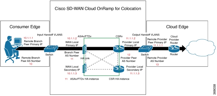
The following image shows how you can aggregate the access to the multicloud applications from multiple branches to regional colocation facilities.

Figure 1. Cisco SD-WAN Cloud onRamp for CoLocations

The solution can serve four specific types of enterprises:

  • Multinational companies that cannot use direct internet connections to the cloud and SaaS platforms due to security restrictions and privacy regulations.

  • Partners and vendors without Cisco SD-WAN but still need connectivity to their customers. They do not want to install SD-WAN routing appliances in their site.

  • Global organizations with geographically distributed branch offices that require high bandwidth, optimum application performance, and granular security.

  • Remote access that need secure VPN connections to an enterprise over inexpensive direct internet links.

The Cisco SD-WAN Cloud onRamp for Colocation solution can be hosted within certain colocation facilities by a colocation IaaS provider. You can select the colocation provider that meets your needs in a region on a regional basis as long as it supports the necessary components.

Deploy Cloud onRamp for Colocation Solution

This topic outlines the sequence of how to get started with the colo devices and build clusters on Cisco vManage. Once a cluster is created and configured, you can follow the steps that are required to activate the cluster. Understand how to design service groups or service chains and attach them to an activated cluster. The supported Day-N operations are also listed in this topic.

  1. Complete the solution prerequisites and requirements. See Prerequisites and Requirements of Cloud onRamp for Colocation Solution .

    • Complete wiring the CSP devices (set up CIMC for initial CSP access) and Cisco Catalyst 9500-40X or Cisco Catalyst 9500-48Y4C switches (set up console server) along with OOB or management switches. Power on all devices.

    • Set up and configure DHCP server. See Provision DHCP Server per Colocation.

  2. Verify the installed version of Cisco NFVIS and install NFVIS, if necessary. See Install Cisco NFVIS Cloud OnRamp for Colocation on Cisco CSP.

  3. Set up or provision a cluster. A cluster constitutes of all the physical devices including CSP devices, and Cisco Catalyst 9500-40X or Cisco Catalyst 9500-48Y4C switches. See Get Started with Cisco SD-WAN Cloud onRamp for CoLocation Solution.

  4. Activate a cluster. See Create and Activate Clusters.

  5. Design service group or service chain. See Manage Service Groups.


    Note

    You can design a service chain and create a service group anytime before creating clusters or activating clusters after all VMs are uploaded to the repository.
  6. Attach or Detach service group and service chains to a cluster. See Attach or Detach a Service Group in a Cluster.


    Note

    Service chains can be attached to a cluster after the cluster is active.
  7. (Optional) Perform all Day-N operations.

Manage Cloud onRamp for Colocation Devices

You can add CSP devices, Catalyst 9500-40X devices, and VNFs through Cisco vManage.

Add Cloud OnRamp Colocation Devices

You can add CSP devices, switch devices, and VNFs using Cisco vManage. When you order the Cisco SD-WAN Cloud onRamp for Colocation solution product identifier (PID), the device information is available from the smart account that can be accessed by Cisco vManage.

Before you begin

Ensure that the setup details are as follows:
  • Cisco SD-WAN setup details such as, Cisco vManage IP address and credentials, Cisco vBond IP address and credentials

  • NFVIS setup details such as, Cisco CSP device CIMC IP address and credentials or UCSC CIMC IP address and credentials

  • Able to access both the switch consoles

Procedure


Step 1

From the Cisco vManage menu, choose Tools > SSH Terminal to start an SSH session with Cisco vManage.

Step 2

Choose a CSP device or a switch device.

Step 3

Enter the username and password for the CSP device or switch device, and click Enter.

Step 4

Get the PID and serial number (SN) of a CSP device.

The following sample output shows the PID for one of the CSP devices.

CSP# show pl
platform-detail hardware_info Manufacturer "Cisco Systems Inc"
platform-detail hardware_info PID CSP-5444
platform-detail hardware_info SN WZP224208MB
platform-detail hardware_info hardware-version 74-105773-01
platform-detail hardware_info UUID da39edec-d831-e549-b663-9e407afd5ac6
platform-detail hardware_info Version 4.6.0-15

The output shows both the CSP device PID and serial number.

Step 5

Get the serial number of both the Catalyst 9500 switch devices.

The following sample shows the serial number of the first switch.

Switch1# show version
Cisco IOS XE Software, Version 17.03.03
Cisco IOS Software [Amsterdam], Catalyst L3 Switch Software (CAT9K_IOSXE), Version 17.3.3, RELEASE SOFTWARE (fc2)
Technical Support: http://www.cisco.com/techsupport
Copyright (c) 1986-2021 by Cisco Systems, Inc.
Compiled Fri 26-Feb-21 02:01 by mcpre
Technology Package License Information: 

------------------------------------------------------------------------------
Technology-package                                     Technology-package
Current                        Type                       Next reboot  
------------------------------------------------------------------------------
network-advantage   	Smart License                 	 network-advantage   
dna-advantage       	Subscription Smart License    	 dna-advantage                 
AIR License Level: AIR DNA Advantage
Next reload AIR license Level: AIR DNA Advantage


Smart Licensing Status: Registration Not Applicable/Not Applicable

cisco C9500-40X (X86) processor with 1331521K/6147K bytes of memory.
Processor board ID FCW2229A0RK
1 Virtual Ethernet interface
96 Ten Gigabit Ethernet interfaces
4 Forty Gigabit Ethernet interfaces
2048K bytes of non-volatile configuration memory.
16777216K bytes of physical memory.
1638400K bytes of Crash Files at crashinfo:.
1638400K bytes of Crash Files at crashinfo-1:.
11264000K bytes of Flash at flash:.
11264000K bytes of Flash at flash-1:.

Base Ethernet MAC Address          : 00:aa:6e:f3:02:00
Motherboard Assembly Number        : 73-18140-03
Motherboard Serial Number          : FOC22270RF8
Model Revision Number              : D0
Motherboard Revision Number        : B0
Model Number                       : C9500-40X
System Serial Number               : FCW2229A0RK
CLEI Code Number                   : 

From this output, you can know the Catalyst 9500 switch series and the serial number.

Step 6

Create a .CSV file with the PID and serial number records for all the CSP devices and Catalyst 9500 switches in a colocation cluster.

For example, from the information available from Steps 4,5, the CSV-formatted file can be as follows:

C9500-40,FCW2229A0RK CSP-5444,SN WZP224208MB
Note 

You can create a single .CSV file for all devices in a colocation cluster.

Step 7

Upload all the CSP and switch devices using Cisco vManage. For more information, see Uploading a device authorized serial number file.


After upload, you can see all the CSP and switch devices listed in the table of devices.

Delete Cloud OnRamp for Colocation Devices

To delete the CSP devices from Cisco vManage, perform the following steps:

Before you begin

Ensure that you consider the following:

Procedure


Step 1

From the Cisco vManage menu, choose Configuration > Certificates.

Step 2

For the desired device, click and choose Invalid.

Step 3

In the Configuration > Certificates window, click Send to Controller.

Step 4

In the Configuration > Devices window, for the desired device, click and choose Delete WAN Edge.

Step 5

Click OK to confirm the deletion of the device.


Deleting a device removes the serial and chassis numbers from the WAN edge router serial number list, and also permanently removes the configuration from Cisco vManage.

Manage Clusters

Use the Cloud onRamp for Colocation screen to configure a colocation cluster and service groups that can be used with the cluster.

The three steps to configure are:

A colocation cluster is a collection of two to eight CSP devices and two switches. The supported cluster templates are:

  • Small cluster—2 Cisco Catalyst 9500-40X or Cisco Catalyst 9500-48Y4C+2 CSP

  • Medium Cluster—2 Cisco Catalyst 9500-40X or Cisco Catalyst 9500-48Y4C+4 CSP

  • Large Cluster—2 Cisco Catalyst 9500-40X or Cisco Catalyst 9500-48Y4C+6 CSP

  • X-Large Cluster—2 Cisco Catalyst 9500-40X or Cisco Catalyst 9500-48Y4C+8 CSP


Note

Ensure that you add a minimum of two CSP devices one-by-one to a cluster. You can keep adding three, four, and so on, up to a maximum of eight CSP devices. You can edit a Day-N configuration of any cluster, and add pairs of CSP devices to each site up to a maximum of eight CSP devices.


Ensure that all devices that you bring into a cluster have the same software version.


Note

You can’t use the CSP-5444 and CSP-5456 devices in the same cluster.


Following are the cluster states:

  • Incomplete—When a cluster is created from the Cisco vManage interface without providing the minimum requirement of two CSP devices and two switches. Also, cluster activation is not yet triggered.

  • Inactive—When a cluster is created from the Cisco vManage interface after providing the minimum requirement of two CSP devices and two Switches, and cluster activation is not yet triggered.

  • Init—When the cluster activation is triggered from the Cisco vManage interface and Day-0 configuration push to the end devices is pending.

  • Inprogress—When one of the CSP devices within a cluster comes up with control connections, the cluster moves to this state.

  • Pending—When the Day-0 configuration push is pending or VNF install is pending.

  • Active—When a cluster is activated successfully and NCS has pushed the configuration to the end device.

  • Failure—If Cisco Colo Manager has not been brought up or if any of the CSP devices that failed to receive an UP event.

A cluster transitioning to an active state or failure state is as follows:

  • Inactive > Init > Inprogress > Pending > Active—Success

  • Inactive > Init > Inprogress > Pending > Failure—Failure

Provision and Configure Cluster

This topic describes about activating a cluster that enables deployment of service chains.

To provision and configure a cluster, perform the following:

  1. Create a colocation cluster by adding two to eight CSP devices and two switches.

    CSP devices can be added to a cluster and configured using Cisco vManage before bringing them up. You can configure CSP devices and Catalyst 9K switches with the global features such as, AAA, default user (admin) password, NTP, syslog, and more.

  2. Configure colocation cluster parameters including IP address pool input such as, service chain VLAN pool, VNF management IP address pool, management gateway, VNF data plane IP pool, and system IP address pool.

  3. Configure a service group.

    A service group consists of one or more service chains.


    Note

    You can add a service chain by selecting one of the predefined or validated service chain template, or create a custom one. For each service chain, configure input and output VLAN handoff and service chain throughput or bandwidth, as mentioned.


  4. Configure each service chain by selecting each VNF from the service template. Choose a VNF image that is already uploaded to the VNF repository to bring up the VM along with required resources (CPU, memory, and disk). Provide the following information for each VNF in a service chain:

    • The specific VM instance behavior such as, HA, shared VM can be shared across service chains.

    • Day-0 configuration values for tokenized keys and not part of the VLAN pool, management IP address, or data HA IP address. The first and last VMs handoff-related information such as peering IP and autonomous system values must be provided. The internal parameters of a service chain are automatically updated by Cisco vBond Orchestrator from the VLAN, or Management, or Data Plane IP address pool provided.

  5. Add the required number of service chains for each service group and create the required number of service groups for a cluster.

  6. To attach a cluster to a site or location, activate the cluster after all configuration is complete.

    You can watch the cluster status change from In progress to active or error in the Task View window.

To edit a cluster:

  1. Modify the activated cluster by adding or deleting service groups or service chains.

  2. Modify the global features configuration such as, AAA, system setting, and more.

You can predesign a service group and service chain before creating a cluster. You can then attach the service group with a cluster after the cluster is active.

Create and Activate Clusters

This topic provides the steps on how you can form a cluster with CSP devices, Cisco Catalyst switches as a single unit, and provision the cluster with cluster-specific configuration.

Before you begin

  • Ensure that you synchronize the clocks for Cisco vManage and CSP devices. To synchronize a clock for CSP devices, configure the NTP server for CSP devices when you enter information about cluster settings.

  • Ensure that you configure the NTP server for Cisco vManage and Cisco vBond Orchestrator. To configure the NTP server, see the Cisco SD-WAN System and Interface Configuration Guide.

  • Ensure that you configure the OTP for the CSP devices to bring up the CSP devices. See Bring Up Cloud Services Platform in Cisco SD-WAN Cloud OnRamp for Colocation Solution Guide.

  • Ensure that you power on both the Catalyst 9500 switches and ensure that they are operational.

Procedure


Step 1

From the Cisco vManage menu, choose Cisco vManage, click Configuration > Cloud OnRamp for Colocation.

  1. Click Configure & Provision Cluster.

  2. Provide the following information:

    Table 1. Cluster Information

    Field

    Description

    Cluster Name

    The cluster name can contain 128 alphanumeric characters.

    Description

    The description can contain 2048 alphanumeric characters.

    Site ID

    The overlay network site identifier. Ensure that the value you enter for Site ID is similar to the organizations Site ID structure for the other Cisco SD-WAN overlay elements.

    Location

    The location can contain 128 alphanumeric characters.

    Cluster Type

    To configure a cluster in a multitenant mode so that it can be shared across multiple tenants, choose Shared.

    Note 

    In the single-tenant mode, the cluster type Non Shared is selected by default.

  3. To configure switches, click a switch icon in the Switches box. In the Edit Switch dialog box, enter a switch name and choose the switch serial number from the drop-down list. Click Save.

    The switch name can contain128 alphanumeric characters.

    The switch serial numbers that you view in the drop-down list are obtained and integrated with Cisco vManage using the PnP process. These serial numbers are assigned to switches when you order Cisco SD-WAN Cloud onRamp for Colocation solution PID on the CCW and procure the switch devices.

    Note 

    You can keep the serial number field blank for switch devices and CSP devices, design your colocation cluster, and then edit the cluster later to add the serial number after you procure the devices. However, you can’t activate a cluster with the CSP devices or switch devices without the serial numbers.

  4. To configure another switch, repeat Step c.

  5. To configure CSP devices, click a CSP icon in the Appliances box. The Edit CSP dialog box is displayed. Provide a CSP device name and choose the CSP serial number from the drop-down list. Click Save.

    The CSP device name can contain 128 alphanumeric characters.

  6. Configure OTP for the CSP devices to bring up the devices.

  7. To add remaining CSP devices, repeat Step e.

  8. Click Save.

    After you create a cluster, on the cluster configuration window, an ellipsis enclosed in a yellow circle appears next to a device where the serial number isn't assigned for the device. You can edit a device to enter the serial numbers.
  9. To edit a CSP device configuration, click a CSP icon, and perform the process mentioned in substep e.

  10. To set the mandatory and optional global parameters for a cluster, on the cluster configuration page, enter the parameters for Cluster Configuration. See Cluster Configuration.

  11. Click Save.

    You can view the cluster that you created in a table on the cluster configuration page.
Step 2

To activate a cluster,

  1. Click a cluster from the cluster table.

  2. For the desired cluster, click and choose Activate.


When you activate the cluster, Cisco vManage establishes a DTLS tunnel with the CSP devices in the cluster, where it connects with the switches through Cisco Colo Manager. When the DTLS tunnel connection is running, a CSP device in the cluster is chosen to host the Cisco Colo Manager. Cisco Colo Manager starts up and Cisco vManage sends global parameter configurations to the CSP devices and Cisco Catalyst 9500 switches. For information about cluster activation progress, see Progress of Cluster Activation.

Note

In Cisco vManage Release 20.7.x and earlier releases, the Cisco Colo Manager (CCM) and CSP device configuration tasks time out 30 minutes after the tasks are created. In the case of long-running image installation operations, these configuration tasks may time out and fail, while the cluster activation state continues to be in a pending state.

From Cisco vManage Release 20.8.1, the CCM and CSP device configuration tasks time out 30 minutes after the last heartbeat status message that Cisco vManage received from the target devices. With this change, long-running image installation operations do not cause configuration tasks to fail after a predefined interval of time after task creation.


Cluster Configuration

The cluster configuration parameters are:

Login Credentials
  1. On the Cluster Topology window, click Add next to Credentials. In the Credentials configuration window, enter the following:

    • (Mandatory) Template Name—The template name can contain 128 alphanumeric characters.

    • (Optional) Description—The description can contain 2048 alphanumeric characters.

  2. Click New User.

    • In the Name field, enter the username.

    • In the Password field, enter the password and confirm the password in the Confirm Password field.

    • In the Role drop-down list, select administrators.

  3. Click Add.

    The new user with username, password, and role with action appears.
  4. Click Save.

    The login credentials for the new user are added.

  5. To cancel the configuration, click Cancel.

  6. To edit the existing credential for the user, click Edit and save the configuration.

Resource Pool
  1. On the Cluster Topology window, click Add next to Resource Pool. In the Resource Pool configuration window, enter values for the following fields:

    • Name—The name of the IP address pool should contain 128 alphanumeric characters.

    • Description—The description can contain 2048 alphanumeric characters.

  2. In the DTLS Tunnel IP field, enter the IP addresses to be used for the DTLS tunnel. To enter multiple IP addresses, separate them by commas. To enter a range, separate the IP addresses with a hyphen (for example, 172.16.0.180-172.16.255.190).

  3. In the Service Chain VLAN Pool field, enter the VLAN numbers to be used for service chains. To enter multiple numbers, separate them by commas. To enter a numeric range, separate the numbers with a hyphen (for example, 1021-2021).

    Consider the following points when entering the VLAN information:

    1002-1005 are the reserved VLAN values, and they shouldn’t be used in the cluster creation VLAN pool.


    Note

    Valid VNF VLAN pool: 1010-2000 and 1003-2000

    Invalid: 1002-1005 (shouldn’t be used)


    Caution

    1002-1005 isn't allowed for configuration. The VLANs tht are allowed should be contiguous.


    Example: Enter data VLAN pool as 1006-2006. Ensure that this VLAN range isn’t used in the Input/Output VLAN during service chain creations.

  4. In the VNF Data Plane IP Pool field, enter the IP addresses to be used for auto configuring data plane on a VNF interface. To enter multiple IP addresses, separate them by commas. To enter a range, separate the IP addresses with a hyphen (for example, 10.0.0.1-10.0.0.100).

  5. In the VNF Management IP Pool field, enter the IP addresses to be used for the VNF. To enter multiple IP addresses, separate them by commas. To enter a range, separate the IP addresses with a hyphen (for example, 192.168.30.99-192.168.30.150).


    Note

    These addresses are IP addresses for secure interfaces.


  6. In the Management Subnet Gateway field, enter the IP address of the gateway to the management network. It enables DNS to exit the cluster.

  7. In the Management Mask field, enter the mask value for the failover cluster. For example, /24 and not 255.255.255.0

  8. In the Switch PNP Server IP field, enter the IP address of the switch device.


    Note

    The IP address of the switch is automatically fetched from the management pool, which is the first IP address. You can change it if a different IP address is configured in the DHCP server for the switch.


  9. Click Save.

Port Connectivity
Table 2. Feature History

Feature Name

Release Information

Description

Flexible Topologies

Cisco SD-WAN Release 20.3.1

Cisco vManage Release 20.3.1

Cisco NFVIS Release 4.2.1

This feature provides the ability to flexibly insert the NIC cards and interconnect the devices (CSP devices and Catalyst 9500 switches) within the Cloud onRamp for Colocation cluster. Any CSP ports can be connected to any port on the switches. The Stackwise Virtual Switch Link (SVL) ports can be connected to any port and similarly the uplink ports can be connected to any port on the switches.

Support for SVL Port Configuration on 100G Interfaces

Cisco SD-WAN Release 20.8.1

Cisco vManage Release 20.8.1

Cisco NFVIS Release 4.8.1

With this feature, you can configure SVL ports on 100-G Ethernet interfaces of Cisco Catalyst 9500-48Y4C switches, thus ensuring a high level of performance and throughput.

Prerequisites for Configuring SVL and Uplink Ports
  • When configuring the SVL and uplink ports, ensure that the port numbers you configure on Cisco vManage match the physically cabled ports.

  • Ensure that you assign serial numbers to both the switches. See Create and Activate Clusters.

Configure SVL and Uplink Ports
  • On the Cluster Topology window, click Add next to Port Connectivity.

    In the Port Connectivity configuration window, both the configured switches appear. Hover over a switch port to view the port number and the port type.


Note

For more information about SVL and uplink ports, see Wiring Requirements in the Cisco SD-WAN Cloud OnRamp for Colocation Solution Guide.


Change Default SVL and Uplink Ports

Before you change the default port number and port type, note the following information about Cisco Catalyst 9500-40X and Cisco Catalyst 9500-48Y4C switches:

  • From Cisco vManage Release 20.8.1, you can configure two SVL ports and one Dual-Active Detection (DAD) port when creating a colocation cluster with two Cisco Catalyst 9500-40X switches or two Cisco Catalyst 9500-48Y4C switches.

  • To ensure that SVL and DAD ports are configured correctly for Cisco Catalyst 9500-48Y4C switches, note the following information:

    • Configure the SVL ports on same-speed interfaces, that is, either 25-G interfaces or 100-G interfaces. Ensure that both switches have the same configuration.

    • Configure the DAD port only on 25-G interfaces on both switches.

    • In case of an existing cluster, you can change the SVL ports only if it is inactive.

    • A cluster created in releases earlier than Cisco vManage Release 20.8.1 automatically displays two SVL ports and one DAD port after the upgrade to Cisco vManage Release 20.8.1.

  • In case of Cisco Catalyst 9500-40X switches, you must configure the SVL and DAD ports on 10-G interfaces on both switches.

  • The following are the default SVL, DAD, and uplink ports of Cisco Catalyst 9500 switches:

    Cisco Catalyst 9500-40X

    • SVL ports: Te1/0/38-Te1/0/39, and Te2/0/38-Te2/0/39

      In Cisco vManage Release 20.7.x and earlier releases, the default SVL ports are Te1/0/38-Te1/0/40 and Te2/0/38-Te2/0/40.

    • DAD ports: Te1/0/40 and Te2/0/40

    • Uplink ports: Te1/0/36, Te2/0/36 (input VLAN handoff), Te1/0/37, and Te2/0/37 (output VLAN handoff)

    Cisco Catalyst 9500-48Y4C

    • SVL ports: Hu1/0/49-Hu1/0/50 and Hu2/0/49-Hu2/0/50

      In Cisco vManage Release 20.7.x and earlier releases, the default SVL ports are Twe1/0/46-Twe1/0/48 and Twe2/0/46-Twe2/0/48.

    • DAD ports: Twe1/0/48 and Twe2/0/48

    • Uplink ports: Twe1/0/44, Twe2/0/44 (input VLAN handoff), Twe1/0/45, and Twe2/0/45 (output VLAN handoff) for 25-G throughput.

  • I, E, and S represent the ingress, egress, and SVL ports, respectively.

  • Ensure that the physical cabling is the same as the default configuration, and click Save.

To change the default ports when the connectivity is different for SVL and uplink ports, perform the following:

  1. If both the switches are using the same ports:

    1. Click a port on a switch that corresponds to a physically connected port.

    2. To add the port configuration to the other switch, check the Apply change check box.

    If both the switches aren’t using the same ports:

    1. Click a port on Switch1.

    2. Choose a port type from the Port Type drop-down list.

    3. Click a port on Switch2 and then choose the port type.

  2. To add another port, repeat step 1.

  3. Click Save.

  4. To edit port connectivity information, in the Cluster Topology window, click Edit next to Port Connectivity.


    Note

    You can modify the SVL and uplink ports of a cluster when the cluster hasn’t been activated.


  5. To reset the ports to default settings, click Reset.

The remaining ports (SR-IOV and OVS) on the Cisco CSP devices and the connections with switches are automatically discovered using Link Layer Discovery Protocol (LLDP) when you activate a cluster. You don't need to configure those ports.

Cisco Colo Manager (CCM) discovers switch neighbor ports and identifies whether all Niantic and Fortville ports are connected. If any port isn’t connected, CCM sends notifications to Cisco vManage that you can view in the task view window.

NTP

Optionally, configure the NTP server for the cluster:

  1. On the Cluster Topology window, click Add next to NTP. In the NTP configuration window, enter the following:

    • Template Name—Name of the NTP template should be in alphanumeric characters and the name should contain upto 128 characters.

    • Description—The description should be in alphanumeric characters and can be upto 2048 characters.

  2. In the Preferred server field, enter the IP address of the primary NTP server.

  3. In the Backup server field, enter the IP address of the secondary NTP server.

  4. Click Save.

    The NTP servers are added.

  5. To cancel the NTP server configuration, click Cancel.

  6. To edit the NTP server configuration details, click Edit.

Syslog Server

Optionally, configure the syslog parameters for the cluster:

  1. On the Cluster Topology window, click Add next to Syslog. In the Syslog configuration window, enter the following:

    • Template Name—Name of the system template should be in alphanumeric characters and the name can contian upto 128 characters.

    • Description—The description can be up to 2048 characters and can contain only alphanumeric characters.

  2. In the Severity drop-down list, choose the severity of syslog messages to be logged.

  3. To add a new syslog server, click New Server.

    Type the IP address of a syslog server.

  4. Click Save.

  5. To cancel the configuration, click Cancel.

  6. To edit the existing syslog server configuration, click Edit and save the configuration.

TACACS Authentication
Table 3. Feature History

Feature Name

Release Information

Description

TACACS Authentication

Cisco SD-WAN Release 20.3.1

Cisco vManage Release 20.3.1

This feature allows you to configure the TACACS authentication for users accessing the Cisco CSP and Cisco Catalyst 9500 devices. Authenticating the users using TACACS validates and secures their access to the Cisco CSP and Cisco Catalyst 9500 devices.

The TACACS authentication determines the valid users who can access the Cisco CSP and Cisco Catalyst 9500 devices after a cluster is active.

Points to consider

  • By default, the admin users with Role-based access control (RBAC) are authorized to access the Cisco CSP and Cisco Catalyst 9500 devices.

  • Do not configure the same user with different passwords when configuring using TACACS and RBAC. If same user with a different password is configured on TACACS and RBAC, the RBAC user and password authentication is used. For information about how to configure RBAC on the devices, see Login Credentials.

To authenticate users:

  1. To add TACACS server configuration, on the Cluster Topology window, click Other Settings > Add next to TACACS.

    To edit TACACS server configuration, in the Cluster Topology window, click Other Settings > Edit next to TACACS.

    In the TACACS configuration window, enter information about the following:

    • Template Name—The TACACS template name can contain 128 alphanumeric characters.

    • (Optional) Description—The description can contain 2048 alphanumeric characters.

  2. To add a new TACACS server, click + New TACACS SERVER.

    • In Server IP Address, enter the IPv4 address.

      Use IPv4 addresses for hostnames of TACACS server.

    • In Secret enter the password and confirm the password in Confirm Secret.

  3. Click Add

    The new TACACS server details are listed in the TACACS configuration window.


    Note

    You can add a maximum of four TACACS servers.


  4. To add another TACACS server, repeat step 2 to step 3.

    When authenticating users, if the first TACACS server is not reachable, the next server is verified until all the four servers are verified.

  5. Click Save.

  6. To delete a TACACS server configuration, choose a row from the TACACS server details list and click Delete under Action.


    Note

    To modify an existing TACACS server information, ensure to delete a TACACS server and then add a new server.


  7. To view the TACACS server configuration, in Cisco vManage, click Configuration > Devices.

    For the desired Cisco CSP device or Cisco Catalyst 9500 switch, click ... and choose Running Configuration.

Backup Server Settings

Points to Consider

  • If you don't use an NFS server, Cisco vManage can’t successfully create backup copies of a CSP device for future RMA requirements.

  • The NFS server mount location and configurations are same for all the CSP devices in a cluster.

  • Don't consider an existing device in a cluster as the replacement CSP device.


    Note

    If a replacement CSP device isn’t available, wait until the device appears in Cisco vManage.


  • Don't attach further service chains to a cluster after you identify that a CSP device in the cluster is faulty.

  • The backup operation on a CSP device creates backup files containing NFVIS configuration and VMs (if VMs are provisioned on the CSP device). You can use the following information for reference.

    • An automated backup file is generated and is in the format:

      serial_number + "_" + time_stamp + ".bkup"

      For example,
      WZP22180EW2_2020_06_24T18_07_00.bkup
    • An internal state model is maintained that specifies the status of the overall backup operation and internal states of each backup component:

      • NFVIS: A configuration backup of the CSP device as an xml file, config.xml.

      • VM_Images: All VNF tar.gz packages in data/intdatastore/uploads which are listed individually.

      • VM_Images_Flavors: The VM images such as, img_flvr.img.bkup.

      • Individual tar backups of the VNFs: The files such as, vmbkp.

    • The backup.manifest file contains information of files in the backup package and their checksum for verification during restore operation.

To create backup copies of all CSP devices in a cluster, perform the following steps:

  1. On the Cluster Topology window, click Add next to Backup.

    To edit backup server settings, on the Cluster Topology window, click Edit next to Backup

    In the Backup configuration window, enter information about the following fields:

    • Mount Name—Enter the name of the NFS mount after mounting an NFS location.

    • Storage Space—Enter the disk space in GB.

    • Server IP: Enter the IP address of the NFS server.

    • Server Path: Enter the folder path of the NFS server such as, /data/colobackup

    • Backup: Click Backup to enable it.

    • Time: Set a time for scheduling the backup operation.

    • Interval: Choose from the options to schedule a periodic backup process.

      • Daily: The first backup is created a day after the backup configuration is saved on the device, and everyday thereafter.

      • Weekly: The first backup is created seven days after the backup configuration is saved on the device, and every week thereafter.

      • Once: The backup copy is created on a chosen day and it's valid for the entire lifetime of a cluster. You can choose a future calendar date.

  2. Click Save.

  3. To view the status of the previous five backup operations, use the show hostaction backup status command. To know about the backup status configuration command, see Backup and Restore NFVIS and VM Configurations. To use this command:

    1. In Cisco vManage, click the Tools > SSH Terminal screen to start an SSH session with Cisco vManage.

    2. Choose the CSP device.

    3. Enter the username and password for the CSP device and click Enter to log in to the CSP device and run the show hostaction backup status command.

Restore CSP Device

You can perform the restore operation only by using the CLI on the CSP device that you're restoring.

  1. Use the mount nfs-mount storage command to mount NFS:

    For more information, see Network File System Support.


    Note

    To access the backup file, the configuration for mounting an NFS file system should match the faulty device. You can view this information from other healthy CSP devices as the NFS mount location and configurations are same for all the CSP devices. To view and capture the information, you can do one of the following:

    • In the Cluster Topology window, click Add next to Backup.

    • Use the show running-config command to view the active configuration that is running on a CSP device.


    mount nfs-mount storage { mount-name | server_ip | server_ip | server_path | server_path | storage_space_total_gb | storage_space_total_gb | storage_type | storage_type }

    For example, mount nfs-mount storage nfsfs/ server_ip 172.19.199.199 server_path /data/colobackup/ storage_space_total_gb 100.0 storagetype nfs

  2. Restore the backup information on a replacement CSP device using the hostaction restore command:

    For example,

    hostaction restore except-connectivity file-path nfs:nfsfs/WZP22180EW2_2020_06_24T18_07_00.bkup

    Note

    Specify the except-connectivity parameter to retain the connectivity with the NFS server mounted in Step 2.


  3. Use the show hostaction backup status command to view the status of the previous five backup images and their operational status.

    Also, you can view the backup images from the notifications available on the Cisco vManage Monitor > Logs > Events page.


    Note

    In Cisco vManage Release 20.6.x and earlier releases, you can view the backup images from the notifications available on the Cisco vManage Monitor > Events page.


  4. Use the show hostaction restore-status command on the CSP device to view the status of the overall restore process and each component such as system, image and flavors, VM and so on.

  5. To fix any failure after viewing the status, perform a factory default reset of the device.


    Note

    The factory default reset sets the device to default configuration. Therefore, before performing the restore operation from Steps 1-4 on the replacement device, verify that all the restore operation prerequisites are met.


To know more about how to configure the restore operation on CSP devices, see Backup and Restore NFVIS and VM Configurations.

Progress of Cluster Activation

Table 4. Feature History

Feature Name

Release Information

Description

Monitor Cluster Activation Progress

Cisco SD-WAN Release 20.1.1

This feature displays the cluster activation progress at each step and shows any failures that may occur during the process. The process of activating a cluster takes approximately 30 minutes or longer, and you can monitor the progress using the Cisco vManage task view window and events from the Monitoring page.

To check cluster activation status after activating a cluster, view the progress on the task view window:


Note

In Cisco vManage Release 20.7.x and earlier releases, Cisco Colo Manager (CCM) bring up and activation progress is reported as part of the CLOUD ONRAMP CCM task. This task shows the seven steps in the CCM bring up and activation sequence and indicates whether the sequence was successfully completed or not. The Push Feature Template Configuration task shows the status of the RBAC settings configuration push.

From Cisco vManage Release 20.8.1, CLOUD ONRAMP CCM task is completed when Cisco vManage receives CCM Healthy from the target CSP device. The Push Feature Template Configuration task shows the seven steps in the CCM bring up and activation sequence and indicates whether the sequence was successfully completed or not, along with the status of the RBAC settings configuration push.


Figure 2. Cluster Activation (Cisco vManage Release 20.7.x and earlier)
Figure 3. CLOUD ONRAMP CCM Task (Cisco vManage Release 20.8.1 and later)
Figure 4. Push Feature Template Configuration Task (Cisco vManage Release 20.8.1 and later)

Perform the following verification steps:

  1. To view cluster state and change the state:

    1. From the Cisco vManage menu, choose Configuration > Cloud onRamp for Colocation. For the cluster that is goes into a "PENDING" state, click ..., and choose Sync. This action moves a cluster back to an "ACTIVE" state.

    2. To view if a cluster moves back to an "ACTIVE" state, you can view the successful activation for the cluster.

  2. To view the service groups present on CSP devices, from the Cisco vManage menu, choose Monitor > Devices > Colocation Cluster.

    Cisco vManage Release 20.6.x and earlier: To view the service groups present on CSP devices, from the Cisco vManage menu, choose Monitor > Network > Colocation Clusters.

    Choose a cluster and then choose a CSP device. You can choose and view other CSP devices.

  3. To check if cluster is activated from a CSP device:

    1. From the Cisco vManage menu, choose Configuration > Devices.

    2. View device status of all the CSP devices and ensure that they are in synchronization with Cisco vManage.

    3. View the state of CSP devices and verify that the certificates are installed for CSP devices.


    Note

    If the state of CSP devices doesn’t show "cert installed" for more than five minutes after CSP activation through OTP, see .


    After a cluster is activated from a CSP device, the Cisco Colo Manager (CCM) performs the cluster activation tasks on the Cisco NFVIS host.

  4. To view if CCM is enabled for a CSP device,

    1. From the Cisco vManage menu, choose Monitor > Devices.

      Cisco vManage Release 20.6.x and earlier: From the Cisco vManage menu, choose Monitor > Network.

    2. Click Colocation Cluster.

      Cisco vManage Release 20.6.x and earlier: Click Colocation Clusters.

      View whether CCM is enabled for specific CSP devices.

  5. To monitor CCM health,

    1. From the Cisco vManage menu, choose Monitor > Devices.

      Cisco vManage Release 20.6.x and earlier: From the Cisco vManage menu, choose Monitor > Network.

    2. Click Colocation Cluster.

      Cisco vManage Release 20.6.x and earlier: Click Colocation Clusters.

      View whether CCM is enabled for the desired CSP devices.

    3. For the CCM-enabled CSP device, click the CSP device.

    4. To view CCM health, click Colo Manager.

    If the Cisco Colo Manager status doesn’t change to "HEALTHY" after "STARTING", see the "Troubleshoot Cisco Colo Manager Issues" topic in the Cisco SD-WAN Cloud OnRamp for Colocation Solution Guide .

    If the status of Cisco Colo Manager changes to "HEALTHY" after "STARTING" but the status of Cisco Colo Manager shows IN-PROGRESS for more than 20 minutes after the switch configurations are already complete, see the Switch devices are not calling home to PNP or Cisco Colo Manager topic in the Cisco SD-WAN Cloud OnRamp for Colocation Solution Guide.

View Cluster

To view cluster configuration, perform the following steps:

Procedure


Step 1

From the Cisco vManage menu, choose Configuration > Cloud OnRamp for Colocation.

Step 2

For the desired cluster, click ... and choose View.

The Cluster window displays the switch devices and CSP devices in the cluster and shows the cluster settings that are configured.

You can only view the global parameters of a cluster, configuration of switch devices and CSP devices.
Step 3

Click Cancel to return to the Cluster window.


Edit Cluster

To modify any existing cluster configuration such as global parameters, perform the following steps:

Procedure


Step 1

From the Cisco vManage menu, choose Configuration > Cloud OnRamp for Colocation

Step 2

For the desired cluster, click ... and choose Edit.

The Cluster window displays the switch devices and CSP devices in the cluster and shows the cluster settings that are configured.

Step 3

In the cluster design window, you can modify some of the global parameters. Based on whether a cluster is in active or inactive state, you can perform the following operations on a cluster:

  1. Inactive state:

    • Edit all global parameters, and the Resource Pool parameter.

    • Add more CSP devices (up to eight).

    • Can’t edit the name or serial number of a switch or CSP device. Instead, delete the CSP or switch and add another switch or CSP with a different name and serial number.

    • Delete an entire cluster configuration.

  2. Active state:

    • Edit all global parameters, except the Resource Pool parameter.

      Note 

      You can't change the Resource pool parameter when the cluster is active. However, the only option to change the Resource Pool parameter is to delete the cluster and recreate it with the correct Resource Pool parameter.

    • Can’t edit the name or serial number of a switch or CSP device.

    • Can’t delete a cluster in an active state.

    • Add more CSP devices (up to eight).

Step 4

Click Save Cluster.


Add CSP Device to Cluster

You can add and configure the CSP devices using Cisco vManage.

Before you begin

Ensure that the Cisco NFVIS version that you use is same for all the CSP devices in the cluster.

Procedure


Step 1

From the Cisco vManage menu, choose Configuration > Cloud OnRamp for Colocation

Step 2

For the desired cluster, click ... and choose Add/Delete CSP.

Step 3

To add a CSP device, click + Add CSP. The Add CSP dialog box appears. Enter a name and choose the CSP device serial number. Click Save.

Step 4

To configure a CSP device, click the CSP icon in the CSP box. The Edit CSP dialog box appears. Enter a name and choose the CSP device serial number. Click Save.

The name can contain 128 alphanumeric characters.

Note 

To bring up the CSP devices, ensure that you configure the OTP for the devices.

Figure 5. Add a CSP Device
Step 5

Click Save.

Step 6

After saving, perform the onscreen configuration instructions as shown in the following images:

Step 7

To check whether the CSP device is added, use the Task View window that displays a list of all running tasks.


Delete CSP Devices from Cluster

You can delete CSP devices using Cisco vManage.

Procedure


Step 1

From the Cisco vManage menu, choose Configuration > Cloud OnRamp for Colocation

Step 2

For the desired cluster, click ... and choose Add/Delete CSP.

Step 3

To delete a CSP device, click the CSP icon from the Appliances box.

Step 4

Click Delete.

Step 5

Click Save.

Step 6

Perform the onscreen instructions to proceed with the deletion as shown in the following images.

Step 7

Reset the CSP devices to factory-default settings.

Step 8

To decommission invalid CSP devices, from the Cisco vManage menu, choose Configuration > Devices.

Step 9

For the CSP devices that are in the deactivated cluster, click the ... and choose Decommission WAN Edge.

This action provides new tokens to the devices.


If an HA service chain is deployed on a CSP device that is deleted, the corresponding HA service chains are deleted from the CSP device that hosts the HA instances.

Delete CSP with CCM

Procedure

Step 1

Determine the CSP device that hosts the CCM.

Step 2

If CCM Enabled is true on a CSP device and you decide to delete this CSP device, for the device, click ... and choose Add/Delete CSP.

From the Montior window, you can view whether CCM is enabled. The following image shows how where you can view the CCM status.

Figure 6. CSP Device with CCM

When the CSP device that you choose to remove from a cluster, runs the service chain monitoring service and CCM, ensure that you click Sync for the cluster. Clicking the sync button starts the service chain health monitoring service on a different CSP device and continues monitoring the existing service chain health.

Ensure that Cisco vManage has control connections to all the CSP devices for a cluster so that it can bring up CCM instance on another CSP device.

Note 

For Cisco vManage Release 20.8.x and earlier releases, if you delete a CSP device hosting a CCM instance, you have to add a CSP device to bring up the CCM instance on one or more of the CSP devices.


After you delete a CSP device with CCM, the CCM instance starts on another CSP device on the cluster.

Note

The service chain monitoring is disabled until the CCM instance doesn't start in any of the remaining CSP devices.


Replace Cisco CSP Devices After RMA

SUMMARY STEPS

  1. From the Cisco vManage menu, choose Configuration > Cloud OnRamp for Colocation
  2. For the desired cluster, click ... and choose RMA.
  3. Do the following in the RMA dialog box:

DETAILED STEPS


Step 1

From the Cisco vManage menu, choose Configuration > Cloud OnRamp for Colocation

Step 2

For the desired cluster, click ... and choose RMA.

Step 3

Do the following in the RMA dialog box:

  1. Select Appliance: Choose a CSP device that you want to replace.

    All CSP devices in a specific colocation cluster are displayed in the format, CSP Name-<Serial Number>.

  2. Choose a serial number for a new CSP device from the drop-down list.

  3. Click Save.


After saving, you can view the configuration.

Return of Materials of Cisco CSP Devices

Table 5. Feature History

Feature Name

Release Information

Description

RMA Support for Cisco CSP Devices

Cisco SD-WAN Release 20.5.1

Cisco vManage Release 20.5.1

This feature allows you to replace a faulty CSP device by creating backup copies of the device, and then restoring the replacement device to a state it was in before the replacement. The VMs running in HA mode operate uninterrupted with continuous flow of traffic during device replacement.

You can now create backup copies and restore NFVIS configurations and VMs.

Points to Consider

  • You can use Network File Storage (NFS) servers to create regular backup copies of the CSP devices.

  • If you’re using an external NFS server for the backup operation, ensure that you maintain and clean the NFS directory regularly. This maintenance ensures that the NFS server has sufficient space for the incoming backup packages.

  • If you don’t use NFS servers, don't configure the backup server settings using Cisco vManage. However, if you're not configuring the backup server settings, you can't restore the replacement device. You can use delete CSP to remove the faulty device, add a new CSP device, and then start provisioning the service chains onto the added CSP device.

RMA Process for Cisco CSP Devices

Ensure that you perform the Return of Materials (RMA) process in the following order:

  1. Create a backup copy of all the CSP devices in a cluster using Cisco vManage. See Backup Server Settings.


    Note

    During CSP device replacement, create a backup copy of the device in the NFS server when creating a cluster using Cisco vManage. Perform one of the following if you’re bringing up a cluster or editing an existing cluster.

    • Bring up a colocation cluster: At the time of cluster creation and activation, provide information about the NFS storage server and backup intervals. If the backup task fails on a CSP device, the device returns an error, but the cluster activation continues. Ensure that you update the cluster after addressing the failure and wait for a successful cluster activation.

    • Edit a colocation cluster: For an existing active cluster, edit the cluster and provide information about the NFS storage server and backup intervals.


  2. Contact Cisco Technical Support to get a replacement CSP device. See Cisco Cloud Services Platform 5000 Hardware Installation Guide for more information about replacing a CSP device.

  3. Rewire the replacement Cisco CSP device with the Cisco Catalyst 9500 switches to move the wiring of the faulty device to the replacement device.

  4. Verify that the Cisco CSP ISO image running on the replacement device is the same that was running on the faulty device.

  5. Restore the replacement device using CLI.

Prerequisites and Restrictions for Backup and Restore of CSP Devices

Prerequisites

Backup Operation

  • The connectivity to the NFS server from CSP devices should be established before configuring the backup server settings using Cisco vManage.

  • The backup directory on the NFS server should have write permission.

  • The external NFS server should be available, reachable, and maintained. The maintenance of the external NFS server requires you to check the available storage space and network reachability regularly.

  • The schedule for the backup operation should be synced with the local date and time on the CSP device.

Restore Operation

  • The replacement device should have the same resources as the faulty device. These resources are, Cisco NFVIS image version, CPU, memory and storage as the faulty CSP device.

  • The connectivity between the replacement device and switch ports should be same as the faulty device and switches.

  • The PNIC wiring of the replacement device should match the faulty device on the Catalyst 9500 switches.

    For example,

    If slot-1/port-1 (eth1-1) on the faulty device is connected to switch-1 and port, 1/0/1, then connect slot-1/port-1 (eth1-1) of the replacement device to the same switch port, such as switch-1 and port, 1/0/1.

  • The onboarding of the replacement device should be completed using the PnP process for CSP devices.

  • To prevent the loss of backup access during the restore operation, the configuration for mounting an NFS server to access the backup package should match the configuration on the faulty device.

    You can view configuration information from other CSP devices as the NFS mount location and configurations are same for all the CSP devices. To view the active configuration that is running on a healthy CSP device, use the show running-config command. Use this active configuration information when creating a mount point during the restore operation.

    For example,

    nfvis# show running-config mount 
    mount nfs-mount storage nfsfs/
    storagetype            nfs
    storage_space_total_gb 123.0
    server_ip              172.19.199.199
    server_path            /data/colobackup/
    !
  • The authentication of the replacement device with the Cisco SD-WAN controllers using the OTP process should be completed after restoring the replacement device.


    Note

    Use the request activate chassis-number chassis-serial-number token token-number command to authenticate a device by logging in to Cisco NFVIS.


  • The replacement device shouldn't have any configuration other than the configuration of the faulty device.

Restrictions

Backup Operation

  • The periodic backup operation doesn't start during the upgrade of a CSP device.

  • If the NFS folder path isn't available on the NFS server, the backup operation doesn't start.

  • Only one backup operation can occur at a specific time.

  • The backup operation fails if the available disk space on the NFS server is less than the combined size of the VM export size and tar.gz VM packages.

  • The backup device information can only be restored on a replacement CSP device and not on any existing device that is already part of the cluster.

  • The NFS mount configurations can’t be updated after they are configured for a CSP device. To update, delete the NFS configuration and reapply an updated configuration to the NFS server and reconfigure the backup schedule. Perform this update when the backup operation isn't in progress.

Restore Operation

  • Only one restore operation can occur at a specific time.

  • If a backup file doesn’t exist in the NFS server, the restore operation doesn't start.

  • The restore operation isn't supported when you convert a cluster from a single tenant mode to multitenant mode, and conversely.

Remove Cluster

To decommission an entire cluster , perform the following steps:

Procedure


Step 1

From the Cisco vManage menu, choose Configuration > Certificates.

Step 2

Verify the Validate column for the CSP devices that you wish to delete, and click Invalid.

Step 3

For the invalid devices, click Send to Controllers.

Step 4

From the Cisco vManage menu, choose Configuration > Cloud OnRamp for Colocation.

Step 5

For the cluster that has invalid CSP devices, click ... and choose Deactivate.

If the cluster is attached to one or more service groups, a message appears that displays the service chains hosting the VMs that are running on the CSP device and whether you can continue with the cluster deletion. However, although you confirm the deletion of a cluster, you’re not allowed to remove the cluster without detaching the service groups that are hosted on this CSP device. If the cluster isn’t attached to any service group, a message appears that gets a confirmation from you about the cluster deletion.

Note 

You can delete the cluster, if necessary, or can keep it in deactivated state.

Step 6

To delete the cluster, choose Delete.

Step 7

Click Cancel if you don't wish to delete the cluster.

Step 8

To decommission invalid devices, from the Cisco vManage menu, choose Configuration > Devices.

Step 9

For the devices that are in the deactivated cluster, click ... and choose Decommission WAN Edge.

This action provides new tokens to your devices.

Step 10

Reset the devices to the factory default by using the command:

factory-default-reset all

Step 11

Log into Cisco NFVIS by using admin as the login name and Admin123# as the default password.

Step 12

Reset switch configuration and reboot switches. See the Troubleshooting chapter in Cisco SD-WAN Cloud OnRamp for Colocation Solution Guide.


Reactivate Cluster

To add new CSP devices or when CSP devices are considered for RMA process, perform the following steps:

Procedure


Step 1

From the Cisco vManage menu, choose Configuration > Devices.

Step 2

Locate the devices that are in a deactivated cluster.

Step 3

Get new token from Cisco vManage for the devices.

Step 4

Log into Cisco NFVIS using admin as the login name and Admin123# as the default password.

Step 5

Use the request activate chassis-number chassis-serial-number token token-number command.

Step 6

Use Cisco vManage to configure the colocation devices and activate the cluster. See Create and Activate Clusters.

If you've deleted the cluster, recreate and then activate it.

Step 7

From the Cisco vManage menu, choose Configuration > Certificates. Locate and verify status of the colocation devices.

Step 8

For the desired device that should be valid, click Valid.

Step 9

For the valid devices, click Send to Controllers.


Manage Service Groups

A service group consists of one or more service chains. You can configure a service group using Cisco vManage. A service chain is the structure of a network service, and consists of a set of linked network functions.

Create Service Chain in a Service Group

A service group consists of one or more service chains.
Table 6. Feature History

Feature Name

Release Information

Feature Description

Monitor Service Chain Health

Cisco SD-WAN Release 19.2.1

This feature lets you configure periodic checks on the service chain data path and reports the overall status. To enable service chain health monitoring, NFVIS version 3.12.1 or later should be installed on all CSP devices in a cluster.

Procedure


From the Cisco vManage menu, choose Configuration > Cloud OnRamp for Colocation

  1. Click Service Group and click Create Service Group. Enter the service group name, description, and colocation group.

    The service group name can contain 128 alphanumeric characters.

    The service group description can contain 2048 alphanumeric characters.

    For a multitenant cluster, choose a colocation group or a tenant from the drop-down list. For a single-tenant cluster, the colocation group admin is chosen by default.

  2. Click Add Service Chain.

  3. In the Add Service Chain dialog box, enter the following information:

    Table 7. Add Service Chain Information

    Field

    Description

    Name

    The service chain name can contain 128 alphanumeric characters.

    Description

    The service chain description can contain alphanumeric 2048 characters.

    Bandwidth

    The service chain bandwidth is in Mbps. The default bandwidth is 10 Mbps and you can configure a maximum bandwidth of 5 Gbps.

    Input Handoff VLANS and Output Handoff VLANS

    The Input VLAN handoff and output VLAN handoff can be comma-separated values (10, 20), or a range from 10–20.

    Monitoring

    A toggle button that allows you to enable or disable service chain health monitoring. The service chain health monitoring is a periodic monitoring service that checks health of a service chain data path and reports the overall service chain health status. By default, the monitoring service is disabled.

    A service chain with subinterfaces such as, SCHM (Service Chain Health Monitoring Service) can only monitor the service chain including the first VLAN from the subinterface VLAN list.

    The service chain monitoring reports status based on end-to-end connectivity. Therefore, ensure that you take care of the routing and return traffic path, with attention to the Cisco SD-WAN service chains for better results.

    Note 
    • Ensure that you provide input and output monitoring IP addresses from input and output handoff subnets. However, if the first and last VNF devices are VPN terminated, you don't need to provide input and output monitoring IP addresses.

      For example, if the network function isn’t VPN terminated, the input monitoring IP can be 192.0.2.1/24 from the inbound subnet, 192.0.2.0/24. The inbound subnet connects to the first network function and the output monitoring IP can be, 203.0.113.11/24 that comes from outbound subnet, 203.0.113.0/24 of the last network function of a service chain.

    • If the first or last VNF firewall in a service chain is in transparent mode, you can't monitor these service chains.

    Service Chain

    A topology to choose from the service chain drop-down list. For a service chain topology, you can choose any of the validated service chains such as, Router - Firewall - Router, Firewall, Firewall - Router. See the Validated Service Chains topic in Cisco SD-WAN Cloud OnRamp Colocation Solution Guide. You can also create a customized service chain. See Create Custom Service Chain.
  4. In the Add Service Chain dialog box, click Add.

    Based on the service chain configuration information, a graphical representation of the service group with all the service chains and the VNFs automatically appear in the design view window. A VNF or PNF appears with a "V" or "P" around the circumference for a virtual a physical network function. It shows all the configured service chains within each service group. A check mark next to the service chain indicates that the service chain configuration is complete.

    After you activate a cluster, attach it with the service group and enable monitoring service for the service chain, when you bring up the CSP device where CCM is running. Cisco vManage chooses the same CSP device to start the monitoring service. The monitoring service monitors all service chains periodically in a round robin fashion by setting the monitoring interval to 30 minutes. See Monitor Cloud onRamp Colocation Clusters.

  5. In the design view window, to configure a VNF, click a VNF in the service chain.

    The Configure VNF dialog box appears.
  6. Configure the VNF with the following information and perform the actions, as appropriate:

    Note 

    The following fields are available from Cisco vManage Release 20.7.1:

    • Disk Image/Image Package (Select File)

    • Disk Image/Image Package (Filter by Tag, Name and Version)

    • Scaffold File (Select File)

    • Scaffold File (Filter by Tag, Name and Version)

    Table 8. VNF Properties of Router and Firewall

    Field

    Description

    Image Package

    Choose a router, firewall package.

    Disk Image/Image Package (Select File)

    Choose a tar.gz package or a qcow2 image file.

    Disk Image/Image Package (Filter by Tag, Name and Version)

    (Optional) Filter an image or a package file based on the name, version, and tags that you specified when uploading a VNF image.

    Scaffold File (Select File)

    Choose a scaffold file.

    Note 
    • This field is mandatory if a qcow2 image file has been chosen. It is optional if a tar.gz package has been chosen.

    • If you choose both a tar.gz package and a scaffold file, then all image properties and system properties from the scaffold file override the image properties and system properties, including the Day-0 configuration files, specified in the tar.gz package.

    Scaffold File (Filter by Tag, Name and Version)

    (Optional) Filter a scaffold file based on the name, version, and tags that you specified when uploading a VNF image.

    Click Fetch VNF Properties. The available information for the image is displayed in the Configure VNF dialog box.

    Name

    VNF image name

    CPU

    (Optional) Specifies the number of virtual CPUs that are required for a VNF. The default value is 1 vCPU.

    Memory

    (Optional) Specifies the maximum primary memory in MB that the VNF can use. The default value is 1024 MB.

    Disk

    (Optional) Specifies disk in GB required for the VM. The default value is 8 GB.

    A dialog box with any custom tokenized variables from Day-0 that requires your input appears. Provide the values.

    In the following image, all IP addresses, VLAN, and autonomous system within the green box are system-specific information that is generated from the VLAN, IP pools provided for the cluster. The information is automatically added into the Day-0 configurations of VMs.

    The Day-0 configurations of VMs are automatically populated for the Cloud Edge Service Chain.

    The following images are a sample configuration for VNF IP addresses and autonomous system numbers, in Cisco vManage.

    If you're using a multitenant cluster and a comanged scenario, configure the Cisco SD-WAN VM by entering the values for the following fields and the remaining fields, as required for the service chain design:

    Note 

    To join the tenant overlay network, the provider should provide correct values for the following fields.

    Field

    Description

    Serial Number

    The authorized serial number of a Cisco SD-WAN device. The service provider can get the device serial number from the tenant before creating the service chain.

    OTP

    The OTP of the Cisco SD-WAN device that is available after authenticating it with Cisco SD-WAN Controllers. The service provider can get the OTP for the corresponding serial number from the tenant before creating the service chain.

    Site Id

    The identifier of the site in the tenant Cisco SD-WAN overlay network domain in which the Cisco SD-WAN device resides, such as a branch, campus, or data center. The service provider can get the site Id from the tenant before creating the service chain.

    Tenant ORG Name

    The tenant organization name that is included in the Certificate Signing Request (CSR). The service provider can get the organization name from the tenant before creating the service chain.

    System IP connect to Tenant

    The IP address to connect to the tenant overlay network. The service provider can get the IP address from the tenant before creating the service chain.

    Tenant vBond IP

    The IP address of the tenant Cisco vBond Orchestrator. The service provider can get the Cisco vBond Orchestrator IP address from the tenant before creating the service chain.

    For edge VMs such as first and last VM in a service chain, you must provide the following addresses as they peer with a branch router and the provider router.

    Table 9. VNF Options for First VM in Service Chain

    Field

    Mandatory or Optional

    Description

    Firewall Mode

    Mandatory

    Choose Routed or Transparent mode.

    Note 

    Firewall mode is applicable to firewall VMs only.

    Enable HA

    Optional

    Enable HA mode for the VNF.

    Termination

    Mandatory

    Choose one of the following modes:

    • L3 mode selection with subinterfaces that are in trunk mode

      <type>selection</type> <val help="L3 Mode With Sub-interfaces(Trunked)" display="VNF-Tagged">vlan</val>

    • L3 mode with IPSEC termination from a consumer-side and rerouted to the provider gateway

      <val help="L3 Mode With IPSEC Termination From Consumer and Routed to Provider GW" display="Tunneled">vpn</val>

    • L3 mode with access mode (nontrunk mode)

      <val help="L3 Mode In Access Mode (Non-Trunked)" display="Hypervisor-Tagged">routed</val>

  7. Click Configure. The service chain is configured with the VNF configuration.

  8. To add another service chain, repeat the procedure from Steps b-g.

  9. Click Save.


The new service group appears in a table under the Service Group. To view the status of the service chains that are monitored, use the Task View window, which displays a list of all running tasks along with the total number of successes and failures. To determine the service chain health status, use the show system:system status command on the CSP device that has service chain health monotioring enabled.

QoS on Service Chains

Table 10. Feature History

Feature Name

Release Information

Description

QoS on Service Chains

Cisco SD-WAN Release 20.1.1

This feature classifies the network traffic based on the Layer 2 virtual local-area network (VLAN) identification number. The QoS policy allows you to limit the bandwidth available for each service chain by applying traffic policing on bidirectional traffic. The bidirectional traffic is the ingress side that connects Cisco Catalyst 9500-40X switches to the consumer and egress side that connects to the provider.

Prerequisites

  • Ensure that you use the Quality of Service (QoS) traffic policing on service chains that do not have shared VNF and PNF devices.


    Note

    You cannot apply QoS policy on service chains with shared VNF devices where input and output VLANs are same for multiple service chains.


  • Ensure that you use the following versions of software for QoS traffic policing:

    Software

    Release

    Cisco NFVIS Cloud OnRamp for Colocation

    4.1.1 and later

    Catalyst 9500-40X

    16.12.1 and later

The QoS policing policy is applied on the network traffic based on the following workflow:

  1. Cisco vManage saves the bandwidth, input, or output VLAN information to VNF and PNF devices. To provide bandwidth and VLAN information, see Create Service Chain in a Service Group.

  2. CCM saves the bandwidth, input, or output VLAN values information to the Cisco Catalyst 9500-40X or Cisco Catalyst 9500-48Y4C switches.

  3. CCM creates corresponding class-maps and policy-maps in Cisco Catalyst 9500-40X or Cisco Catalyst 9500-48Y4C switches based on VLAN match criteria.

  4. CCM applies input service-policy on the ingress and egress ports.


Note

From Cisco vManage Release 20.7.1, the QoS traffic policy on service chains is not supported for Cisco Catalyst 9500 switches.

  • If an active cluster is upgraded to Cisco vManage Release 20.7.1 and CSPs 4.7.1, and if there are service chains provisioned prior to upgrade, the QoS configuration will be removed from switches during the upgrade automatically.

  • When new service chains are provisioned in Cisco vManage Release 20.7.1, the QoS policy will not be configured on switches.

  • Similarly, new clusters created in Cisco vManage Release 20.7.1 will not configure QoS configuration for service chains on switches.


Clone Service Groups

Table 11. Feature History

Feature Name

Release Information

Description

Clone Service Groups in Cisco vManage

Cisco SD-WAN Release 20.5.1

Cisco vManage Release 20.5.1

This feature allows you to create copies of service groups for different RBAC users, without having to enter the same configuration information multiple times. By cloning a service group, you can easily create service chains by leveraging the stored service chain templates.

When you clone or create copies of service chains, remember the following:

  • Cisco vManage copies all configuration information of a service group to a cloned service group regardless of whether the cloned service group is attached to a cluster.

  • Verify the CSV file and ensure that configuration information has a matching service group name during CSV file upload. Otherwise, an unmatched service group name can result in an error message during CSV file upload.

  • To get an updated list of service group configuration values, always download service group configuration properties from the service group design view.

Procedure


Step 1

From the Cisco vManage menu, choose Configuration > Cloud OnRamp for Colocation

Step 2

Click Service Group.

The service group configuration page appears and all the service groups are displayed.
Step 3

For the desired service group, click ... and choose Clone Service Group.

A clone of the original service group appears in the service group design view. Note the following points:

  • By default, the cloned service group name and VM names are suffixed with a unique string.

  • To view any VM configuration, click a VM in service chains.

  • Cisco vManage marks the service chains that require configuration as Unconfigured, next to the edit button of the service chain.

Step 4

Modify the service group name, if required. Provide a description for the service group.

Step 5

To configure a service chain, use one of the following methods:

  • Click the edit button for a service chain, enter the values, and then click Save.
  • Download the configuration values from a CSV file, modify the values, upload the file, and then click Save. See Steps 6, 7, 8 on how to download, modify, and upload a CSV file.

The cloned service group appears on the service group configuration page. You can now download the updated service group configuration values.

Step 6

To download the cloned service group configuration values, do one of the following:

Note 

The download and upload of a CSV file is supported for creating, editing, and cloning of the service groups that aren’t attached to a cluster.

  • On the service group configuration page, click a cloned service group, click More Actions to the right of the service group, and choose Download Properties (CSV).
  • In the service group design view, click Download CSV in the upper right corner of the screen.

Cisco vManage downloads all configuration values of the service group to an Excel file in CSV format. The CSV file can consist of multiple service groups and each row represents configuration values for one service group. To add more rows to the CSV file, copy service group configuration values from existing CSV files and paste them in this file.

For example, ServiceGroup1_Clone1 that has two service chains with one VM in each of the service chains is represented in a single row.

Note 

In the Excel file, the headers and their representation in the service chain design view is as follows:

  • sc1/name represents the name of the first service chain.

  • sc1/vm1/name represents the name of the first VNF in the first service chain.

  • sc2/name represents the name of the second service chain.

  • sc2/vm2/name represents the name of the second VNF in the second service chain.

Step 7

To modify service group configuration values, do one of the following:

  • To modify the service group configuration in the design view, click a cloned service group from the service group configuration page.

    Click any VM in service chains to modify the configuration values, and then click Save.

  • To modify the service group configuration using the downloaded Excel file, enter the configuration values in the Excel file manually. Save the Excel file in CSV format.
Step 8

To upload a CSV file that includes all the configuration values of a service group, click a service group in the service group configuration page, and then click Upload CSV from the right corner of the screen.

Click Browse to choose a CSV file, and then click Upload.

You can view the updated values displayed for the service group configuration.
Note 

You can use the same CSV file to add configuration values for multiple service groups. But, you can update configuration values for a specific service group only, when uploading a CSV file using Cisco vManage.

Step 9

To know the representation of service group configuration properties in the CSV file and Cisco vManage design view, click a service group from the service group configuration page.

Click Show Mapping Names.

A text appears next to all the VMs in the service chains. Cisco vManage displays this text after mapping it with the configuration properties in the CSV file.

Create Custom Service Chain

You can customize service chains,
  • By including extra VNFs or add other VNF types.

  • By creating new VNF sequence that isn’t part of the predefined service chains.

Procedure


Step 1

Create a service group and service chains within the service group. See Create Service Chain in a Service Group.

Step 2

In the Add Service Chain dialog box, enter the service chain name, description, bandwidth, input VLAN handoff, output VLAN handoff, monitoring health information of a service chain, and service chain configuration. Click Add.

For the service chain configuration, choose Create Custom from the drop-down. An empty service chain in the design view window is available.

Step 3

To add a VNF such as a router, load balancer, firewall, and others, click a VNF icon and drag the icon to its proper location within the service group box. After adding all required VNFs and forming the VNF service chain, configure each of the VNFs. Click a VNF in the service group box. The Configure VNF dialog box appears. Enter the following parameters:

  1. Choose the software image to load from the Disk Image/Image Package (Select File) drop-down list.

    Note 

    You can select a qcow2 image file from Cisco vManage Release 20.7.1.

  2. Choose a scaffold file from the Scaffold File (Select File) drop-down list if you have chosen a qcow2 image file.

    Note 

    This option is available from Cisco vManage Release 20.7.1.

  3. Optionally, filter an image, a package file, or a scaffold file based on the name, version, and tags that you specified when uploading a VNF image.

    Note 

    This option is available from Cisco vManage Release 20.7.1.

  4. Click Fetch VNF Properties.

  5. In the Name field, enter a name of the VNF.

  6. In the CPU field, enter the number of virtual CPUs required for the VNF.

  7. In the Memory field, enter the amount of memory in megabytes to be allocated for the VNF.

  8. In the Disk field, enter the amount of memory for storage in gigabytes to be allocated for the VNF.

  9. Enter VNF-specific parameters, as required.

    Note 

    These VNF details are the custom variables that are required for Day-0 operations of the VNF.

  10. Click Configure.

  11. To delete the VNF or cancel the VNF configuration, click Delete or Cancel respectively.


The customized service chains are added to a service group.

Note

You can customize a VNF sequence with only up to four VNFs in a service chain.


Custom Service Chain with Shared PNF Devices

You can customize service chains by adding supported PNF devices.

Caution

Ensure that you don’t share PNF devices across colocation clusters. A PNF device can be shared across service chains, or across service groups. However, a PNF device can now be shared only across a single cluster.
Table 12. Feature History

Feature Name

Release Information

Feature Description

Manage PNF Devices in Service Chains

Cisco SD-WAN Release 19.2.1

This feature lets you add Physical Network Function (PNF) devices to a network, in addition to the Virtual Network function (VNF) devices. These PNF devices can be added to service chains and shared across service chains, service groups, and a cluster. Inclusion of PNF devices in the service chain can overcome the performance and scaling issues caused by using only VNF devices in a service chain.

Before you begin

For more information about validated physical network functions, see the Validated Physical Network Functions topic in the Cisco SD-WAN Cloud OnRamp for Colocation Solution Guide, Release 19.2 book.

To create a customized service chain by adding a router or firewall to an existing service chain, ensure that you note the following points:

  • If a PNF device needs to be managed by Cisco vManage, ensure that the serial number is already available in Cisco vManage, which can then be available for selection during PNF configuration.

  • The FTD device can be in any position in a service chain.

  • An ASR 1000 Series Aggregation Services Routers can only be in the first and last position in a service chain.

  • PNF devices can be added across service chains and service groups.

  • PNF devices can be shared across service groups. They can be shared across service groups by entering the same serial numbers.

  • PNF devices can be shared across a single colocation cluster, and can't be shared across multiple colocation clusters.

Procedure


Step 1

Create a service group and service chains within the service group. See Create Service Chain in a Service Group.

Step 2

In the Add Service Chain dialog box, enter the service chain name, description, bandwidth, input VLAN handoff, output VLAN handoff, monitoring health information of a service chain, and service chain configuration. Click Add.

For the service chain configuration, choose Create Custom from the drop-down list. An empty service chain in the design view window is available. At the left, a set of VNF devices and PNF devices that you can add into the service chain appears. The 'V' in the circumference of VNF devices represents a VNF and 'P' in the circumference of PNF devices represent a PNF.

Note 
Ensure that you choose the Create Custom option for creating service chains by sharing PNF devices.
Step 3

To add a PNF such as physical routers, physical firewalls in a service chain, click the required PNF icon, and drag the icon to the proper location within the service chain box.

After adding all required PNF devices, configure each of them.

  1. Click a PNF device in the service chain box.

    The Configure PNF dialog box appears. To configure a PNF, enter the following parameters:

  2. Check HA Enabled if HA is enabled for the PNF device.

  3. If the PNF is HA enabled, ensure that you add the HA serial number in HA Serial.

    If the PNF device is FTD, enter the following information.

    1. In the Name field, enter a name of the PNF.

    2. Choose Routed or Transparent mode as the Firewall Mode.

    3. In the PNF Serial field, enter the serial number of the PNF device.

    If the PNF device is ASR 1000 Series Aggregation Services Routers, enter the following information.

    1. Check the vManaged check box if the device is managed by Cisco vManage.

    2. Click Fetch Properties.

    3. In the Name field, enter a name of the PNF.

    4. In the PNF Serial field, enter the serial number of the PNF device.

  4. Click Configure.

Step 4

To add service chains and share PNF devices, repeat from Step 2.

Step 5

To edit an existing PNF configuration, click the PNF.

Step 6

In the Share NF To drop-down list, choose the service chains with which the PNF should be shared.

After a PNF is shared, if you hover over a PNF, the respective shared PNF devices are highlighted in blue color. However, the PNFs from different service groups aren’t highlighted in blue color. After you choose an NF to be shared, a blue color rim appears. If the same PNF is shared across multiple service chains, it can be used in different positions by dragging and placing the PNF icons in a specific positon.

Figure 7. Single PNF in a Service Chain

The following image shows a service chain that consists of a single PNF, Ftd_Pnf (not shared with other service chains).

Figure 8. Two PNF Devices in Service Chains

The following image shows service chains that consist of two PNFs, FTdv_PNF shared across service chain 1 (SC1) and service chain 2 (SC2) and ASR_PNF (non-shared).

Figure 9. Three PNF Devices in Service Chains

The following image shows service chains that consist of three PNF devices in two different positions along with Cisco vManage configuration.

Step 7

To delete or cancel a Network Function configuration, click Delete or Cancel respectively.


You must attach the service groups to a colocation cluster. After attaching service groups that contain PNF devices, the PNF configuration isn’t automatically pushed to the PNF devices unlike VNF devices. Instead, you must manually configure the PNF device by noting configuration that is generated on the Monitor window. The VLANs must be also configured on the Cisco Catalyst 9500-40X switch devices. See the ASR 1000 Series Aggregation Services Routers Configuration Guides and Cisco Firepower Threat Defense Configuration Guides for more information about the specific PNF configuration.

Custom Service Chain with Shared VNF Devices

You can customize service chains by including supported VNF devices.
Table 13. Feature History

Feature Name

Release Information

Feature Description

Share VNF Devices Across Service Chains

Cisco SD-WAN Release 19.2.1

This feature lets you share Virtual Network Function (VNF) devices across service chains to improve resource utilisation and reduce resource fragmentation.

Before you begin

Ensure that you note the following points about sharing VNF devices:

  • You can share only the first, last, or both first and last VNF devices in a service chain.

  • You can share a VNF with a minimum of one more service chain and maximum up to five service chains.

  • Each service chain can have a maximum of up to four VNF devices in a service chain.

  • You can share VNF devices only in the same service group.

Procedure


Step 1

Create a service group and service chains within the service group. See Create Service Chain in a Service Group.

Step 2

In the Add Service Chain dialog box, enter the service chain name, description, bandwidth, input VLAN handoff, output VLAN handoff, monitoring health information of a service chain, and service chain configuration. Click Add.

For the service chain configuration, choose Create Custom from the drop-down list. An empty service chain in the design view window is available. At the left, a set of VNF devices and PNF devices that you can add into the service chain appears. The 'V' in the circumference of VNF devices represents a VNF and 'P' in the circumference of PNF devices represent a PNF.

Note 

Ensure that you choose the Create Custom option for creating a shared VNF package.

Step 3

To add a VNF such as a router, load balancer, firewall, and others, click a VNF icon from the left panel, and drag the icon to a proper location within the service chain box.

After adding all required VNF devices, configure each of them.

  1. Click a VNF in the service chain box.

    The Configure VNF dialog box appears. To configure VNF, enter the following parameters:

  2. From the Image Package drop-down list, choose the software image to load.

    To create a customized VNF package from Cisco vManage, see Create Customized VNF Image.

  3. Click Fetch VNF Properties.

  4. In the Name field, enter a name of the VNF.

  5. In the CPU field, enter the number of virtual CPUs required for the VNF.

  6. In the Memory field, enter the amount of memory in megabytes to be allocated for the VNF.

  7. In the Disk field, enter the amount of memory for storage in gigabytes to be allocated for the VNF.

  8. Enter VNF-specific parameters, as required. See Create Service Chain in a Service Group for more information about VNF-specific properties.

    These VNF-specific parameters are the custom user variables that are required for Day-0 operations of a VNF.

    For a complete information about the list of user and system variables for different VNF types when located at various positions, see .

    Note 
    Ensure that you enter the values of the user variables if they are defined as mandatory, and the system variables are automatically set by Cisco vManage.
  9. Click Configure.

Step 4

To share VNF devices, repeat from Step 2.

Step 5

To edit an existing VNF configuration, click the VNF.

Step 6

Scroll down the VNF configuration to find the Share NF To field. From the Share NF To drop-down list, choose the service chains with which the VNF should be shared.

After a VNF is shared, if you hover over a VNF, the specific shared VNF devices are highlighted in blue color. After you choose an NF to be shared, a blue rim appears on it.

Step 7

To delete a VNF or cancel the VNF configuration, click Delete or Cancel respectively.


You must attach service groups to a cluster.

View Service Groups

To view service groups, perform the following steps:

Procedure


Step 1

From the Cisco vManage menu, choose Configuration > Cloud OnRamp for Colocation

Step 2

Click Service Group.

Step 3

For the desired service group, click ... and choose View.

You can view the service chains in the design window.


Edit Service Groups

Before attaching a service group with a cluster, you can edit all parameters. After attaching a service group with a cluster, you can only edit monitoring configuration parameters. Also, after attaching a service group, you can only add new service chains but not edit or attach a service chain. Hence, ensure that you detach a service group from a cluster before editing an existing service chain. To edit and delete a service group, perform the following steps:

Procedure


Step 1

From the Cisco vManage menu, choose Configuration > Cloud OnRamp for Colocation.

Step 2

Click Service Group.

Step 3

For the desired service group, click ... and choose Edit.

Step 4

To modify either service chain configuration or modify a VNF configuration, click a router or firewall VNF icon.

Step 5

To add new service chains, click Add Service Chain.


Attach or Detach a Service Group in a Cluster

To complete the Cisco SD-WAN Cloud onRamp for Colocation configuration, you must attach service groups to a cluster. To attach or detach a service group to and from a cluster, perform the following steps:

Procedure


Step 1

From the Cisco vManage menu, choose Configuration > Cloud OnRamp for Colocation.

Step 2

Click ... adjacent to the corresponding cluster and choose Attach Service Groups.

Step 3

In the Attach Service Groups dialog box, choose one or more service groups in Available Service Groups and click Add to move the selected groups to Selected Service Groups.

Step 4

Click Attach.

Step 5

To detach a service group from a cluster, click ... adjacent to the corresponding cluster and choose Detach Service Groups.

You can’t attach or detach a single service chain within a service group.
Step 6

In the Config Preview window that is displayed, click Cancel to cancel the attach or detach task.

Note 
.
Step 7

To verify if service groups are attached or detached, you can view the status using Cisco vManage. Note the following points:

If a colocation cluster moves to PENDING state, for a cluster, click ..., and choose Sync. This action moves the cluster back to ACTIVE state. The Sync option keeps Cisco vManage synchronized with the colocation devices.


Manage VM Catalog and Repository

Table 14. Feature History

Feature Name

Release Information

Description

Support for Cisco VM Image Upload in qcow2 Format

Cisco SD-WAN Release 20.7.1

Cisco vManage Release 20.7.1

This feature allows you to upload a virtual machine image to Cisco vManage in qcow2 format. Earlier, you could upload only a prepackaged image file in tar.gz format.

Cisco vManage supports uploading a prepackaged Cisco virtual machine image, tar.gz, or an image in qcow2 format. It is mandatory to upload a scaffold file if you choose a qcow2 image file. Similarly, you can now select either an image package file or a qcow2 image file with a scaffold file when configuring a Virtual Network Function (VNF) during service chain creation.

A scaffold file contains the following components:

  • VNF metadata (image_properties.xml)

  • System-generated variables from cluster resource pools for service chaining (system_generated_propeties.xml)

  • Tokenized Day-0 configuration files

  • Package manifest file (package.mf)

Alternatively, you can package the VM image by providing a root disk image in any of the supported formats (qcow2). Use the linux command-line NFVIS VM packaging tool, nfvpt.py to package the qcow2 or alternatively create a customized VM image using Cisco vManage. See Create Customized VNF Image.

A VM is SR-IOV capable means sriov_supported is set to true in image_properties.xml in the vm package *.tar.gz. Also, the service chain network is automatically connected to SR-IOV network. If sriov_supported is set to false, an OVS network is created on the data port channel. It’s attached to VM VNICs for service chaining by using the OVS network. For the Cloud OnRamp for Colocation solution, a VM uses homogeneous type of network in service chains. This type of network means it’s either OVS or SR-IOV, and not a combination of SR-IOV and OVS.

Only two data VNICs are attached to any VM–one for inbound traffic and the other for outbound traffic. If more than two data interfaces are required, use subinterfaces configuration within the VM. The VM packages are stored in the VM catalog.


Note

Each VM type such as firewall can have multiple VM images that are uploaded to Cisco vManage from same or different vendors and added to a catalog. Also, different versions that are based on the release of the same VM can be added to a catalog. However, ensure that the VM name is unique.


The Cisco VM image format can be bundled as *.tar.gz and can include:

  • Root disk images to boot the VM.

  • Package manifest for checksum validation of the file listing in the package.

  • Image properties file in XML format that lists the VM meta data.

  • (Optional) Day-0 configuration, other files that are required to bootstrap the VM.

  • (Optional) HA Day-0 configuration if VM supports stateful HA.

  • System-generated properties file in XML format that lists the VM system properties.

VM images can be hosted on both HTTP server local repository that Cisco vManage hosts or on the remote server.

If VM is in Cisco NFVIS supported VM package format such as, tar.gz, Cisco vManage performs all the processing and you can provide variable key and values during VNF provisioning.


Note

Cisco vManage manages the Cisco VNFs, and the Day-1 and Day-N configurations within VNF aren’t supported for other VNFs. See the Cisco NFVIS Configuration Guide, VM Image Packaging for more information about VM package format and content, and samples on image_properties.xml and manifest (package.mf).

To upload multiple packages for the same VM, same version, communication manager (CM) type, ensure that one of the three values (name, version, VNF type) are different. Then, you can repackage the VM *.tar.gz to be uploaded.


Upload VNF Images

The VNF images are stored in the Cisco vManage software repository. These VNF images are referenced during service chain deployment, and then they are pushed to Cisco NFVIS during service chain attachment.

Procedure


Step 1

From the Cisco vManage menu, choose Maintenance > Software Repository.

Step 2

To add a prepackaged VNF image, click Virtual Images, and then click Upload Virtual Image.

Step 3

Choose the location to store the virtual image.

  • To store the virtual image on the local Cisco vManage server and download it to CSP devices over a control plane connection, click vManage. The Upload VNF’s Package to vManage dialog box appears.

    1. Drag and drop the virtual image file or the qcow2 image file to the dialog box or click Browse to choose the virtual image from the local Cisco vManage server. For example, CSR.tar.gz, ASAv.tar.gz, or ABC.qcow2

    2. If you upload a file, specify the type of the uploaded file: Image Package or Scaffold. Optionally, specify a description of the file and add custom tags to the file. The tags can be used to filter images and scaffold files when creating a service chain.

    3. If you upload a qcow2 image file, specify the service or VNF type: FIREWALL or ROUTER. Optionally, specify the following:

      • Description of the image

      • Version number of the image

      • Checksum

      • Hash algorithm

      You can also add custom tags to the file that can be used to filter images and scaffold files when creating a service chain.

      Note 
      • It is mandatory to upload a scaffold file if you choose a qcow2 image file.

      • The option to select a qcow2 image file is available from Cisco vManage Release 20.7.1. In Cisco vManage Release 20.6.1 and earlier releases, you can select only a tar.gz file.

    4. Click Upload to add the image to the virtual image repository. The virtual image repository table displays the added virtual image, and it available for installing on the CSP devices.

  • To store the image on a remote Cisco vManage server and then download it to CSP devices, click Remote Server - vManage. The Upload VNF’s Package to Remote Server-vManage dialog box appears.

    1. In the vManage Hostname/IP Address field, enter the IP address of an interface on Cisco vManage server that is in the management VPN (typically, VPN 512).

    2. Drag and drop the virtual image file or the qcow2 image file to the dialog box, or click Browse to choose the virtual image from the local Cisco vManage server.

    3. If you upload a file, specify the type of the uploaded file: Image Package or Scaffold. Optionally, specify a description of the file and add custom tags to the file. The tags can be used to filter images and scaffold files when creating a service chain.

    4. If you upload a qcow2 image file, specify the service or VNF type: FIREWALL or ROUTER. Optionally, specify the following:

      • Description of the image

      • Version number of the image

      • Checksum

      • Hash algorithm

      You can also add custom tags to the file that can be used to filter images and scaffold files when creating a service chain.

      Note 
      • It is mandatory to upload a scaffold file if you choose a qcow2 image file.

      • The option to select a qcow2 image file is available from Cisco vManage Release 20.7.1. In Cisco vManage Release 20.6.1 and earlier releases, you can select only a tar.gz file.

    5. Click Upload to add the image to the virtual image repository. The virtual image repository table displays the added virtual image, and it is available for installing on the CSP devices.


You can have multiple VNF entries such as a firewall from same or from different vendors. Also, you can add different versions of VNF that are based on the release of the same VNF. However, ensure that the VNF name is unique.

Create Customized VNF Image

Before you begin
You can upload one or more qcow2 images in addition to a root disk image as an input file along with VM-specific properties, bootstrap configuration files (if any), and generate a compressed TAR file. Through custom packaging, you can:
  • Create a custom VM package along with image properties and bootstrap files (if needed) into a TAR archive file.

  • Tokenize custom variables and apply system variables that are passed with the bootstrap configuration files.

Ensure that the following custom packaging requirements are met:

  • Root disk image for a VNF–qcow2

  • Day-0 configuration files–system and tokenized custom variables

  • VM configuration–CPU, memory, disk, NICs

  • HA mode–If a VNF supports HA, specify Day-0 primary and secondary files, NICs for a HA link.

  • Additional Storage–If more storage is required, specify predefined disks (qcow2), storage volumes (NFVIS layer)

Procedure

Step 1

From the Cisco vManage menu, choose Maintenance > Software Repository .

Step 2

Click Virtual Images > Add Custom VNF Package.

Step 3

Configure the VNF with the following VNF package properties and click Save.

Table 15. VNF Package Properties
Field Mandatory or Optional Description

Package Name

Mandatory

The filename of the target VNF package. It’s the Cisco NFVIS image name with .tar or .gz extensions.

App Vendor

Mandatory

Cisco VNFs or third-party VNFs.

Name

Mandatory

Name of the VNF image.

Version

Optional

Version number of a program.

Type

Mandatory

Type of VNF to choose.

Supported VNF types are: Router, Firewall, Load Balancer, and Other.

Step 4

To package a VM qcow2 image, click File Upload, and browse to choose a qcow2 image file.

Step 5

To choose a bootstrap configuration file for VNF, if any, click Day 0 Configuration and click File Upload to browse and choose the file.

Include the following Day-0 configuration properties:
Table 16. Day-0 Configuration

Field

Mandatory or Optional

Description

Mount

Mandatory

The path where the bootstrap file gets mounted.

Parseable

Mandatory

A Day-0 configuration file can be parsed or not.

Options are: Enable or Disable. By default, Enable is chosen.

High Availability

Mandatory

High availability for a Day-0 configuration file to choose.

Supported values are: Standalone, HA Primary, HA Secondary.

Note 

If any bootstrap configuration is required for a VNF, create a bootstrap-config or a day0-config file.

Step 6

To add a Day-0 configuration, click Add, and then click Save. The Day-0 configuration appears in the Day 0 Config File table. You can tokenize the bootstrap configuration variables with system and custom variables. To tokenize variables of a Day-0 configuration file, click View Configuration File next to the desired Day-0 configuration file. In the Day 0 configuration file dialog box, perform the following tasks:

Note 

The bootstrap configuration file is an XML or a text file, and contains properties specific to a VNF and the environment. For a shared VNF, see the topic, Additional References in Cisco SD-WAN Cloud OnRamp for Colocation Solution Guide for the list of system variables that must be added for different VNF types..

  1. To add a system variable, in the CLI configuration dialog box, select, and highlight a property from the text fields. Click System Variable. The Create System Variable dialog box appears.

  2. Choose a system variable from the Variable Name drop-down list, and click Done. The highlighted property is replaced by the system variable name.

  3. To add a custom variable, in the CLI configuration dialog box, choose and highlight a custom variable attribute from the text fields. Click Custom Variable. The Create Custom Variable dialog box appears.

  4. Enter the custom variable name and choose a type from Type drop-down list.

  5. To set the custom variable attribute, do the following:

    • To ensure that the custom variable is mandatory when creating a service chain, click Type next to Mandatory.

    • To ensure that a VNF includes both primary and secondary day-0 files, click Type next to Common.

  6. Click Done, and then click Save. The highlighted custom variable attribute is replaced by the custom variable name.

Step 7

To upload extra VM images, expand Advance Options, click Upload Image, and then browse to choose an extra qcow2 image file. Choose the root disk, Ephemeral disk 1, or Ephemeral disk 2, and click Add. The newly added VM image appears in the Upload Image table.

Note 

Ensure that you don’t combine ephemeral disks and storage volumes when uploading extra VM images.

Step 8

To add the storage information, expand Add Storage, and click Add volume. Provide the following storage information and click Add. The added storage details appear in the Add Storage table.

Table 17. Storage Properties

Field

Mandatory or Optional

Description

Size

Mandatory

The disk size that is required for the VM operation. If the size unit is GiB, the maximum disk size can be 256 GiB.

Size Unit

Mandatory

Choose size unit.

The supported units are: MIB, GiB, TiB.

Device Type

Optional

Choose a disk or CD-ROM. By default, disk is chosen.

Location

Optional

The location of the disk or CD-ROM. By default, it’s local.

Format

Optional

Choose a disk image format.

The supported formats are: qcow2, raw, and vmdk. By default, it’s raw.

Bus

Optional

Choose a value from the drop-down list.

The supported values for a bus are: virtio, scsi, and ide. By default, it’s virtio.

Step 9

To add VNF image properties, expand Image Properties and enter the following image information.

Table 18. VNF Image Properties

Field

Mandatory or Optional

Description

SR-IOV Mode

Mandatory

Enable or disable SR-IOV support. By default, it’s enabled.

Monitored

Mandatory

VM health monitoring for those VMs that you can bootstrap.

The options are: enable or disable. By default, it’s enabled.

Bootup Time

Mandatory

The monitoring timeout period for a monitored VM. By default, it’s 600 seconds.

Serial Console

Optional

The serial console that is supported or not.

The options are: enable or disable. By default, it’s disabled.

Privileged Mode

Optional

Allows special features like promiscuous mode and snooping.

The options are: enable or disable. By default, it’s disabled.

Dedicate Cores

Mandatory

Facilitates allocation of a dedicated resource (CPU) to supplement a VM's low latency (for example, router and firewall). Otherwise, shared resources are used.

The options are: enable or disable. By default, it’s enabled.

Step 10

To add VM resource requirements, expand Resource Requirements and enter the following information.

Table 19. VM Resource Requirements

Field

Mandatory or Optional

Description

Default CPU

Mandatory

The CPUs supported by a VM. The maximum numbers of CPUs supported are 8.

Default RAM

Mandatory

The RAM supported by a VM. The RAM can range 2–32.

Disk Size

Mandatory

The disk size in GB supported by a VM. The disk size can range 4–256.

Max number of VNICs

Optional

The maximum number of VNICs allowed for a VM. The number of VNICs can from range 8–32 and by default, the value is 8.

Management VNIC ID

Mandatory

The management VNIC ID corresponding to the management interface. The valid range is from 0 to maximum number of VNICs.

Number of Management VNICs ID

Mandatory

The number of VNICs.

High Availability VNIC ID

Mandatory

The VNIC IDs where high availability is enabled. The valid range is from 0–maximum number of VNICs. It shouldn’t conflict with management VNIC Id. By default, the value is 1.

Number of High Availability VNICs ID

Mandatory

The maximum number of VNIC IDs where high availability is enabled. The valid range is 0–(maximum number of VNICs-number of management VNICs-2) and by default, the value is 1.

Step 11

To add day-0 configuration drive options, expand Day 0 Configuration Drive options and enter the following information.

Table 20. Day-0 Configuration Drive Options

Field

Mandatory or Optional

Description

Volume Label

Mandatory

The volume label of the Day-0 configuration drive.

The options are: V1 or V2. By default, the option is V2. V2 is the config-drive label config-2. V1 is config-drive label cidata.

Init Drive

Optional

The Day-0 configuration file as a disk when mounted. The default drive is CD-ROM.

Init Bus

Optional

Choose an init bus.

The supported values for a bus are: virtio, scsi, and ide. By default, it’s ide.


The Software Repository table displays the customized VNF image, and image is available for choosing when creating a custom service chain.

View VNF Images

Procedure

Step 1

From the Cisco vManage menu, choose Maintenance > Software Repository.

Step 2

Click Virtual Images.

Step 3

To filter the search results, use the filter option in the search bar.

The Software Version column provides the version of the software image.

The Software Location column indicates where the software images are stored. Software images can be stored either in the repository on the Cisco vManage server or in a repository in a remote location.

The Version Type Name column provides the type of firewall.

The Available Files column lists the names of the VNF image files.

The Update On column displays when the software image was added to the repository.

Step 4

For the desired VNF image, click ... and choose Show Info.


Delete VNF Images

Procedure

Step 1

From the Cisco vManage menu, choose Maintenance > Software Repository.

Step 2

Click Virtual Images. The images in the repository are displayed in a table.

Step 3

For the desired image, click ... and choose Delete.


Note

If you're downloading a VNF image to a device, you can’t delete the VNF image until the download process completes.


Note

If the VNF image is referenced by a service chain, it can’t be deleted.


Upgrade Cisco NFVIS Using Cisco vManage

To upload and upgrade Cisco NFVIS, the upgrade image must be available as an archive file that can be uploaded to the Cisco vManage repository using Cisco vManage. After you upload the Cisco NFVIS image, the upgraded image can be applied to a CSP device by using the Software Upgrade window in Cisco vManage. You can perform the following tasks when upgrading Cisco NFVIS software using Cisco vManage:

Upload NFVIS Upgrade Image

Procedure


Step 1

Download the Cisco NFVIS upgrade image from a prescribed location to your local system. You can also download the software image to an FTP server in your network.

Step 2

From the Cisco vManage menu, choose Maintenance > Software Repository .

Step 3

Click Add New Software > Remote Server/Remote Server - vManage.

You can either store the software image on a remote file server, on a remote Cisco vManage server, or on a Cisco vManage server.

Cisco vManage server: Saves software images on a local Cisco vManage server.

Remote server: Saves the URL pointing to the location of the software image and can be accessed using an FTP or HTTP URL.

Remote Cisco vManage server: Saves software images on a remote Cisco vManage server and location of the remote Cisco vManage server is stored in the local Cisco vManage server.

Step 4

To add the image to the software repository, browse and choose the Cisco NFVIS upgrade image that you had downloaded in Step1.

Step 5

Click Add|Upload.


The Software Repository table displays the added NFVIS upgrade image, and it’s available for installing on the CSP devices. See the Software Repository topic in the Cisco SD-WAN Configuration Guides.

Upgrade a CSP Device with a Cisco NFVIS Upgrade Image

Before you begin

Ensure that the Cisco NFVIS software versions are the files that have .nfvispkg extension.

Procedure


Step 1

From the Cisco vManage menu, choose Maintenance > Software Upgrade > WAN Edge.

Step 2

Check one or more CSP device check boxes for the devices you want to choose.

Step 3

Click Upgrade. The Software Upgrade dialog box appears.

Step 4

Choose the Cisco NFVIS software version to install on the CSP device. If software is located on a remote server, choose the appropriate remote version.

Step 5

To automatically upgrade and activate with the new Cisco NFVIS software version and reboot the CSP device, check the Activate and Reboot check box.

If you don’t check the Activate and Reboot check box, the CSP device downloads and verifies the software image. However, the CSP device continues to run the old or current version of the software image. To enable the CSP device to run the new software image, you must manually activate the new Cisco NFVIS software version by choosing the device again and clicking the Activate button in the Software Upgrade window.

Step 6

Click Upgrade.

The Task View window displays a list of all running tasks along with total number of successes and failures. The window periodically refreshes and displays messages to indicate the progress or status of the upgrade. You can easily access the software upgrade status window by clicking the Task View icon located in the Cisco vManage toolbar.

Note 
If two or more CSP devices belonging to the same cluster are upgraded, the software upgrade for the CSP devices happens in a sequence.
Note 

The Set the Default Software Version option isn’t available for the Cisco NFVIS images.


The CSP device reboots and the new NFVIS version is activated on the device. This reboot happens during the Activate phase. The activation can either happen immediately after upgrade if you check the Activate and Reboot check box, or by manually clicking Activate after choosing the CSP device again.

To verify if CSP device has rebooted and is running, use the task view window. Cisco vManage polls your entire network every 90 seconds up to 30 times and shows the status on th task view window.


Note

You can delete a Cisco NFVIS software image from a CSP device if the image version isn’t the active version that is running on the device.

Supported Upgrade Scenarios and Recommended Connections

The following are the various upgrade scenarios and cluster states that determine the use of prescriptive or flexible connections.

Table 21. Supported Connections

Cisco vManage

Cisco NFVIS

Cluster State

Supported Connections

Upgrade from Releases 19.3 or 20.1.1.1 to Release 20.3.1

Upgrade from Releases 3.12 or 4.1 to Releases 4.1.1 or 4.2.1

Cluster created and active inCisco vManage Releases 19.3 or 20.1.1.1

Use prescriptive connections

Use the latest Release, 20.3.1

Use the latest Release, 4.2.1

Cluster created and active in Cisco vManage Release 20.3.1

Can use prescriptive or flexible connections

Upgrade from Release 20.1.1.1 to Release 20.3.1

Upgrade from Release 4.1 to Releases 4.1.1 or 4.2.1

Cluster created and active in Cisco vManage Release 20.1.1.1.

Use prescriptive connections

Upgrade from Release 20.1.1.1 to Release 20.3.1

Upgrade from Release 4.1 to Releases 4.1.1 or 4.2.1

Cluster created and active in Cisco vManage Release 20.1.1.1.

To add a new Cisco CSP device after upgrade, see Add a Cisco CSP device to the cluster after upgrading Cisco vManage and Cisco NFVIS.

Use prescriptive connections

Upgrade from Release 20.1.1.1 to Release 20.3.1

Upgrade from Release 4.1 to Releases 4.1.1 or 4.2.1

Cluster created and active in Cisco vManage Release 20.3.1

Can use prescriptive or flexible connections

Add Cisco CSP Device to Cluster After Upgrading Cisco vManage and Cisco NFVIS

To add a Cisco CSP device to a cluster if the cluster was created before upgrading Cisco vManage to Release 20.3.1, perform the following steps:

  1. Connect the cables for the newly added Cisco CSP device according to prescriptive connections.

  2. Upgrade Cisco NFVIS to Release 4.2.1

  3. Use the following commands on the newly added Cisco CSP device by logging into Cisco NFVIS:

    • request csp-prescriptive-mode

      Requests the newly added Cisco CSP device to run in prescriptive mode.

    • request activate chassis-number chassis number token serial number

      Activates the Cisco CSP device

      Example

      request activate chassis-number 71591a3b-7d52-24d4-234b-58e5f4ad0646 token e0b6f073220d85ad32445e30de88a739

Recommendations Prior to Updating a Cluster

  • To use an already active cluster when you upgrade to the latest release of the Cisco SD-WAN Cloud onRamp for Colocation solution, ensure that you upgrade Cisco vManage and Cisco NFVIS to the latest releases.

  • To create a new cluster when you upgrade to the latest release of the Cisco SD-WAN Cloud onRamp for Colocation solution, ensure that you upgrade Cisco vManage and Cisco NFVIS to the latest releases for flexible connections.

Monitor Operational Status of Cloud OnRamp for Colocation Devices from Cisco vManage

Monitoring colocation devices is the process of reviewing and analyzing a device, such as Cloud Services Platform (CSP) devices and Cisco Colo Manager for health, inventory, availability, and other operation-related processes. You can also monitor the components of CSP devices such as CPU, memory, fan, temperature, and so on. For more information about the Cisco vManage Monitoring screens, see the Cisco SD-WAN Configuration Guides configuration guides.

All notifications are sent to the Cisco vManage notification stream. To use the notification stream command, see Cisco SD-WAN Command Reference.

Procedure


Step 1

From the Cisco vManage menu, choose Monitor > Devices.

Cisco vManage Release 20.6.x and earlier: From the Cisco vManage menu, choose Monitor > Network.

If Cisco vManage can’t reach the CSP devices and Cisco Colo Manager (CCM) cannot reach the switches, the CSP devices and CCM are shown as unreachable.

Step 2

Click a CSP device or a switch from the list by clicking the hostname.

By default, the VNF Status window appears.

Step 3

Click Select Device and to filter the search results for devices, use the Filter option in the search bar.

The following are the categories of information about the device that are displayed:

Step 4

To monitor colocation clusters, from the Cisco vManage menu, choose Monitor > Devices and click Colocation Cluster.

Cisco vManage Release 20.6.x and earlier: To monitor colocation clusters, from the Cisco vManage menu, choose Monitor > Network and click Colocation Clusters.

Step 5

Click the desired cluster name. See Monitor Cloud onRamp Colocation Clusters for more information.


View Cisco Colo Manager Health

You can view Cisco Colo Manager (CCM) health for a device, CCM host system IP, CCM IP, and CCM state. Reviewing this information can help you to determine which VNF to use when you’re designing a network service chain. To view information about VNFs, perform the following steps:

Procedure


Step 1

From the Cisco vManage menu, choose Monitor > Devices.

Cisco vManage Release 20.6.x and earlier: From the Cisco vManage menu, choose Monitor > Network.

The information of all devices is displayed in a tabular format.

Step 2

Click a CSP device from the table.

Step 3

From the left pane, click Colo Manager.

The right pane displays information about the memory usage, CPU usage, uptime, and so on, of the colo manager.


View Information About VNFs

Table 22. Feature History

Feature Name

Release Information

Description

VNF States and Color Codes

Cisco SD-WAN Release 20.1.1

This feature allows you to determine the state of a deployed VM using color codes, which you can view on the Monitor > Devices page. These color codes help you make decisions on creating service chains based on the state of the VM.

Table 23. Feature History

Feature Name

Release Information

Description

Network Utilization Charts for SR-IOV Enabled NICs and OVS Switch

Cisco SD-WAN Release 20.1.1

This feature allows you to view network utilization charts of VM VNICs connected to both SR-IOV enabled NICs and OVS switch. These charts help you determine if the VM utilization is optimal to create service chains.

You can view performance specifications and required resources for each VNF. Reviewing this information can help you to determine which VNF to use when you’re designing a network service. To view information about VNFs, perform the following steps:

Procedure


Step 1

From the Cisco vManage menu, choose Monitor > Devices.

Cisco vManage Release 20.6.x and earlier: From the Cisco vManage menu, choose Monitor > Network.

Cisco vManage displays the VNF information in a tabular format. The table includes information such as CPU use, memory consumption, and disk, and other core parameters that define performance of a network service.

Step 2

Click a CSP device from the table.

Step 3

From the left pane, click VNF Status.

Step 4

From the table, click the VNF name. Cisco vManage displays information about the specific VNF. You can click the network utilization, CPU utilization, memory utilization, and disk utilization to monitor the VNF resources utilization.

The following VNF information is displayed:

Table 24. VNF Information

Chart options bar

VNF information in graphical format

VNF information in color coded format

  • Chart Options drop-down—Click Chart Options drop-down list to select the type of data to display.

  • Time periods—Click either a predefined time period, or a custom time period for which to display data.

Choose a VNF from the Select Device drop-down list to display information for the VNF.

The VNFs are shown in specific colors based on the following operational status of the VNF life cycle:

  • Green—VNF is healthy, deployed, and successfully booted up.

  • Red—VNF deployment or any other operation fails, or VNF stops.

  • Yellow—VNF is transitioning from one state to another.

The right pane displays the following:

  • Filter criteria

  • VNF table that lists information about all VNFs or VMs. By default, the first six VNFs are selected. The network utilization charts for VNICs connected to SR-IOV enabled NICs and OVS switch are displayed.
    Figure 10. VNF Information

    The graphical display plots information for the VNFs that you have selected by checking the check box.

    • Click the check box at the left to select and deselect VNFs. You can select and display information for a maximum of six VNFs at a time.

    • To change the sort order of a column, click the column title.


Monitor Cloud onRamp Colocation Clusters

Table 25. Feature History

Feature Name

Release Information

Description

Network Assurance –VNFs: Stop/Start/Restart

Cisco SD-WAN Release 20.3.1

Cisco vManage Release 20.3.1

This feature provides the capability to stop, start, or restart VNFs on Cisco CSP devices from the Colocation Cluster tab. You can easily perform the operations on VNFs using Cisco vManage.

You can view the cluster information and their health states. Reviewing this information can help you to determine which Cisco CSP device is responsible for hosting each VNF in a service chain. To view information about a cluster, perform the following steps:

Procedure


Step 1

From the Cisco vManage menu, choose Monitor > Devices.

Cisco vManage Release 20.6.x and earlier: From the Cisco vManage menu, choose Monitor > Network.

Step 2

To monitor clusters, click Colocation Cluster.

Cisco vManage Release 20.6.x and earlier: Click Colocation Clusters.

All clusters with relevant information are displayed in a tabular format. Click a cluster name. You can monitor cluster by clicking Config. View and Port Level View.

  • Config. View: The primary part of the window displays the CSP devices and switch devices that form the cluster. In the right pane, you can view the cluster information such as the available and total CPU resources, available and allocated memory, and so on, based on colocation size.

    The detail part of the window contains:

    • Search: To filter the search results, use the Filter option in the search bar.

    • A table that lists information about all devices in a cluster (Cisco CSP devices, PNFs, and switches).

      Click a Cisco CSP device. VNF information is displayed in a tabular format. The table includes information such as VNF name, service chains, number of CPUs, memory consumption, and other core parameters that define performance of a network service chain. See View Information About VNFs .

      To start, stop, or reboot a VNF, for the desired VNF, click ... and choose one of the following operations:

      • Start.

      • Stop.

      • Restart.

    Note 
    Ensure that service chain provisioning is complete and VMs are deployed, before issuing start, stop, restart operations on any of the VNFs in the service chain.

    After you choose an operation on a VNF, wait until the operation is complete before you issue another operation. You can view the progress of an operation from the Task View window.

  • Port Level View: After you activate the cluster, to view the port connectivity details, click Port Level View.

    You can view detailed port connectivity information for the switches and CSP devices in a color coded format based on the SR-IOV and OVS modes.

    To view the mapping of ports between the Catalyst 9500 switches and CSP devices, click or hover over a CSP device.

    Figure 11. Monitor Port Connectivity Details of a Cluster
Step 3

Click Services.

Here, you can view the following:

  • Complete information of a service chain. The first two columns display the name and description of the service chain in the service group and the remaining columns mention about the VNF, PNF statuses, monitoring service enablemement, and the overall health of a service chain. You can also view the colocation user group associated with a service chain. The various health statuses and their representations are:

    • Healthy—An up arrow in green. A service chain is in 'Healthy' status when all the VNF, PNF devices are running and are in healthy state. Ensure that you configure the routing and policy correctly.

    • Unhealthy—A down arrow in red. If one of the VNFs or PNFs are in unhealthy state, the service chain is reported to be in 'Unhealthy' status. For example, after deploying a service chain, if one of the network function IP address changes on the WAN or LAN side, or the firewall policy isn’t configured to let the traffic pass through, then unhealthy state is reported. This is because the network function or overall service chain is Unhealthy or both are in Unhealthy state.

    • Undetermined—Down arrow in yellow. This state is reported when the health of the service chain can’t be determined. This state is also reported when there’s no status such as healthy or unhealthy available for the monitored service chain over a time period. You can’t query or search a service chain with undetermined status.

      If a service chain consists of a single PNF and PNF is outside the reachability of Cisco vManage, it can’t be monitored. If a service chain consists of a single network function, the firewall that has VPN termination on both sides which can’t be monitored, then it’s reported as Undetermined.

      Note 
      If the status of a service chain is undetermined, you can’t choose the service chain to view the detailed monitoring information.
  • If you had configured a service chain by enabling the monitoring field, then click a service group that is in Healthy or Unhealthy state. The primary part of the service chain monitoring window contains the following elements:

    Graphical display that plots the latency information of the service chain, VNFs, PNFs.

    The detail part of the service chain monitoring window contains:

    • Search: To filter the search results, use the Filter option in the search bar.

    • A table that lists information about all service chains, VNFs, PNFs, their health status, and types.

      • Check the service chain, VNF, PNF check boxes for the service chains, VNFs, PNFs you want to choose.

      • To change the sort order of a column, click the column title.

    The status details column indicates the monitored data path and it provides the per hop analysis.

  • Click Diagram and view the service group with all the service chains and VNFs in the design view window.

  • Click a VNF. You can view CPU, memory, and disk allocated to the VNF in a dialog box.

  • Choose a service group from the Service Groups drop-down. The design view displays the selected service group with all the service chains and VNFs.

Step 4

Click Network Functions.

Here, you can view the following:

  • All the virtual or physical network functions in a tabular format. Use the Show button, and choose to display either a VNF or PNF.

    VNF information is displayed in a tabular format. The table includes information such as VNF name, service chains, colocation user groups, CPU use, memory consumption, and other core parameters that define performance of network service. To view more information about the VNF, click a VNF name. See View Information About VNFs .

  • PNF information is displayed in tabular format. The table includes information such as the serial number and PNF type. To view and note configuration of a specific PNF, click the desired PNF serial number. Ensure that you manually note all the configuration of the PNFs and then configure the PNF devices. For example, the following are some of the PNF configuration where you position the PNF at various locations in the service chain. See the ASR 1000 Series Aggregation Services Routers Configuration Guides and Cisco Firepower Threat Defense Configuration Guides to configure the PNFs manually.

    Figure 12. PNF in the First Position with Service Chain Side Parameters
    Figure 13. PNF in the First Position with Outside Neighbor Information
    Figure 14. PNF Shared Across Two Service Chains

    The ServiceGroup2_chain3 is a PNF-only service chain and therefore no configuration gets generated. The PNF is in the last position of the ServiceGroup2_chain1, so only INSIDE variables gets generated.

    Figure 15. PNF Shared Across Two Service Chains with Outside Neighbor Information

Packet Capture for Cloud onRamp Colocation Clusters

Table 26. Feature History

Feature Name

Release Information

Description

Packet Capture for Cloud onRamp Colocation Clusters

Cisco SD-WAN Release 20.7.1

Cisco vManage Release 20.7.1

This feature lets you capture packets at either the physical network interface card (PNIC) level or the virtual network interface card (VNIC) level on a Cloud Services Platform (CSP) device of a colocation cluster. You can capture packets on one or more PNIC or VNIC on the same device or different devices with different browsers at the same time. This feature lets you gather information about the packet format, and helps in application analysis, security, and troubleshooting.

You can capture packets flowing to, through, and from a CSP device of a colocation cluster. You can capture packets at either the PNIC or the VNIC level on the CSP device.

Supported Ports for Packet Capture for Cloud onRamp Colocation Clusters

Packet capture is supported for the following ports:

Table 27. Supported Ports for Packet Capture

Mode

VNIC Level

PNIC Level

Single Tenancy

OVS-DPDK, HA-OVS-DPDK, SR-IOV, OVS-MGMT

SR-IOV, MGMT

Multitenancy (Role-Based Access Control)

OVS-DPDK, HA-OVS-DPDK, OVS-MGMT

MGMT

Enable Packet Capture on Cisco vManage

Enable the packet capture feature on Cisco vManage before capturing packets at the PNIC or VNIC level on a CSP device of a colocation cluster:

  1. From the Cisco vManage menu, choose Administration > Settings.

  2. In Data Stream, choose Enabled.

Capture Packets at PNIC Level

  1. From the Cisco vManage menu, choose Monitor > Devices.

  2. Click Colocation Cluster, and choose a cluster.

  3. From the list of devices that is displayed, click a CSP device name.

  4. In the left pane, click Packet Capture.

  5. From the PNIC ID drop-down list, choose a PNIC.

  6. (Optional) Click Traffic Filter to filter the packets that you want to capture based on the values in their IP headers.

    Table 28. Packet Capture Filters
    Field Description

    Source IP

    Source IP address of the packet.

    Source Port

    Source port number of the packet.

    Protocol

    Protocol ID of the packet.

    The supported protocols are: ICMP, IGMP, TCP, UDP, ESP, AH, ICMP Version 6 (ICMPv6), IGRP, PIM, and VRRP.

    Destination IP

    Destination IP address of the packet.

    Destination Port

    Destination port number of the packet.

  7. Click Start.

    The packet capture begins, and its progress is displayed:

    • Packet Capture in Progress: Packet capture stops after the file size reaches 20 MB, or 5 minutes after you started packet capture, or when you click Stop.

    • Preparing file to download: Cisco vManage creates a file in libpcap format (a .pcap file).

    • File ready, click to download the file: Click the download icon to download the generated file.

Capture Packets at VNIC Level

  1. From the Cisco vManage menu, choose Monitor > Devices.

  2. Click Colocation Cluster, and choose a cluster.

  3. From the list of devices that is displayed, click a CSP device name.

  4. Choose a VNF, and then click Packet Capture in the left pane.

  5. Alternatively, choose Monitor > Devices > Colocation Cluster. Next, choose a cluster and click Network Functions, choose a VNF, and then click Packet Capture in the left pane.

  6. From the VNIC ID drop-down list, choose a VNIC.

  7. (Optional) Click Traffic Filter to filter the packets to capture based on values in their IP headers. For more information on these filters, see the above section.

  8. Click Start. The packet capture begins, and displays its progress.

Cisco SD-WAN Cloud onRamp for Colocation Multitenancy

Table 29. Feature History

Feature Name

Release Information

Description

Colocation Multitenancy Using Role-Based Access Control

Cisco SD-WAN Release 20.5.1

Cisco vManage Release 20.5.1

This feature enables a service provider to manage multiple colocation clusters and share these clusters across tenants by using multiple colocation groups. In a multitenant setup, service providers don't need to deploy a unique colocation cluster for each tenant. Instead, the hardware resources of a colocation cluster are shared across multiple tenants. With multitenancy, service providers ensure that tenants view only their data by restricting access based on roles of individual tenant users.

Overview of Colocation Multitenancy

In Cisco SD-WAN Cloud onRamp for Colocation multitenancy, a service provider can manage multiple colocation clusters using Cisco vManage in single-tenant mode. A service provider can bring up a multitenant cluster in the same way as bringing up a cluster in a single-tenant mode. A multitenant cluster can be shared across multiple tenants. See Create and Activate Clusters.

The tenants share the hardware resources such as the Cisco Cloud Services Platform (CSP) devices and Cisco Catalyst 9500 devices of a colocation cluster. The following are the key points of this feature.

  • A service provider deploys and configures the Cisco SD-WAN Controllers (Cisco vManage, Cisco vBond Orchestrator, and Cisco vSmart Controller) with valid certificates.

  • A service provider sets up colocation clusters after onboarding the Cisco CSP devices and Cisco Catalyst 9500 switches.

  • Cisco SD-WAN operates in a single-tenant mode and Cisco vManage appears in a single-tenant mode.

  • In a colocation multitenant deployment, a service provider ensures that tenants see only their service chains by, creating roles. A service provider creates roles for each tenant in a colocation group. These tenants are permitted to access and monitor the service chains based on their roles. However, they can’t configure their service chains or change the system-level settings. The roles ensure that tenants can access only the information that they are authorized to view.

  • Each tenant traffic is segmented using VXLAN across the compute devices, and VLAN across the Cisco Catalyst switch fabric.

  • A service provider can provision service chains on a specific cluster.

The following are the two scenarios of a colocation multitenant setup:

  • Service provider owned Cisco SD-WAN devices: In this scenario, the Cisco SD-WAN devices used in a service chain belong to the corresponding service provider. The CSP devices and Catalyst 9500 switches are owned, monitored, maintained by the service provider. The virtual machine (VM) packages are owned, uploaded, and maintained by a service provider. See Monitor Colocation Cluster Devices and Cisco SD-WAN Devices in Comanaged Multitenant Environment.

  • Comanaged Cisco SD-WAN devices: In this scenario, the Cisco SD-WAN devices that are used in a service chain belong to a tenant overlay network. The colocation cluster devices are owned by the service provider, whereas the Cisco SD-WAN devices of a service chain are controlled by the Cisco SD-WAN Controllers (Cisco vManage, Cisco vBond Orchestrator, and Cisco vSmart Controller) of a tenant. The CSP devices and Catalyst 9500 switches are owned, monitored, maintained by the service provider. The VM packages are owned, uploaded, and maintained by a service provider. See Monitor Colocation Cluster Devices and Cisco SD-WAN Devices in Comanaged Multitenant Environment.

Roles and Functionalities in a Multitenant Environment

Multitenant environments include a service provider and multiple tenants. Each role has distinct responsibilities and associated functions.

Service Provider

A service provider owns all the hardware infrastructure and manages the clusters. The service provider also onboards tenants by creating their roles, provisions the service chains for tenants, and can view all the service chains of all the tenants.

A service provider logs in to Cisco vManage as the admin user or a user who has the write permission for the manage users permission. A service provider can add, edit, or delete users and user groups from the Cisco vManage server, and is typically responsible for the following activities:

  • Create and manage clusters for tenants.

  • Upload prepackaged VM image packages and Cisco Enterprise NFV Infrastructure Software (NFVIS) software images on the CSP devices.

  • Create custom colocation groups and role-based access control (RBAC) users.

  • Create service groups and associate a colocation group to multiple service groups.

  • Upgrade CSP devices and Catalyst 9500 switches.

  • Monitor service chains and VMs of all the tenants.

  • Start, stop, or restart operations on any of the tenant virtual network functions (VNFs).

  • Administer Cisco vManage and record system-wide logging of Cisco SD-WAN devices.

Tenants

Tenants can initiate operations on the VNFs for the service chains that belong to themselves, but they can't view, access, or initiate operations on VNFs for the service chains that belong to another tenant. Tenants are responsible for the following activities:

  • Monitor all the service groups and the health status of the service chains that belong to themselves.

  • Monitor event or alarms for VNFs that are a part of the service chains that belong to themselves.

  • Initiate start, stop, or restart operations on VNFs that are a part of the service chains that belongs to themselves.

  • Collaborate with the corresponding service provider for issues, if any, on cluster, service chains, or VNFs.

Recommended Specifications in a Multitenant Environment

We recommend that service providers use the following information to decide on the number of tenants, clusters, service chains per tenant, and VLANs for various colocation sizes:

Table 30. Specifications for a Multitenant Environment

Tenants

Clusters (CPUs)

Service Chains (CPUs) per Tenant

VLANs

150

2 (608)

1 (4)–Small

~300

75-150

2 (608)

2-3 (4-8)–Medium

300-450

25-50

2 (608)

4-6 (12-24)–Large

~400

300

4 (1216)

Small

~600

150-300

4 (1216)

Medium

600-900

50-100

4 (1216)

Large

~800

600

8 (2432)

Small

~1200

300-600

8 (2432)

Medium

900-1200

100-200

8 (2432)

Large

~1050

750

10 (3040)

Small

~1500

375-750

10 (3040)

Medium

600-1500

125-230

10 (3040)

Large

~1250

For example, if a service provider provisions four vCPUs per tenant for a service chain that consists of a single VM, the service provider can onboard approximately 150 tenants on two clusters with eight CSP devices. Each of these tenants or service chains requires 300 hand-off VLANs, one ingress, and one egress VLAN per service chain. .

Assumptions and Restrictions in Colocation Multitenancy

The following sections provide detailed information about the assumptions and restrictions in a colocation multitenant environment.

Assumptions

  • The wiring between Cisco CSP devices and Cisco Catalyst 9500 switches is completed as per the prescriptive connections or flexible topology. To bring up multiple clusters, ensure that the wiring between the CSP devices and Catalyst 9500 switches of a cluster are in the same way as a single cluster. For more information about wiring, see Wiring Requirements.

  • Each Cisco CSP device has two 1-GB management ports that are manually configured as port channels to the out of band (OOB) management switch.

  • A tenant can only monitor the event or alarms from the Monitor window for the VNFs that are a part of the service chains that they own. The tenant-monitoring windows display the corresponding colocation group when a tenant is viewing a service chain.


    Note

    In a comanaged multitenant setup, the service provider provisions service chains for tenants by gathering the required information from tenants. For example, a tenant provides the tenant organization name, tenant Cisco vBond Orchestrator IP address, tenant site ID, system IP address, and so on, out of band. See Create Service Chain in a Service Group.


Restrictions

  • Altering a colocation cluster from a single-tenant mode to a multitenant mode and conversely isn’t supported.

  • Sharing VNF devices across multiple tenants isn't supported.

  • Service providers can provision multiple service groups for a tenant. But, the same service group can’t be provisioned for multiple tenants.

  • Upgrading from Cisco SD-WAN Cloud onRamp for Colocation Release 20.4.1 having a single-tenant mode, to Release 20.5.1 or later having a multitenant mode isn’t supported. This restriction means you can’t upgrade from a single-tenant mode to multitenant mode.

  • Multitenancy in single-root IO virtualization enabled (SR-IOV-enabled) physical network interface cards (PNICs) isn't supported; only open virtual switch (OVS) for VNF VNICs is supported. All the PNICs in the CSP devices are in OVS mode because the current SR-IOV drivers don’t support VXLAN. The VNF VNICs are connected to OVS networks, and the ability to forward traffic at the desired speed might reduce.

  • Managing billing and subscription of the resources utilized by tenants isn't supported.

  • In a comanaged multitenant setup, a tenant can monitor only the VNF devices that the tenant owns.

Service Provider Functionalities

Provision a New Tenant

The service provider can provision a new tenant by creating a colocation group, and then provide access to a tenant by creating an RBAC user for the user group associated with the colocation group. RBAC users can perform limited administrative duties within their own tenant environment.

Before you begin

A service provider should bring up clusters in shared mode by establishing control connections with the CSP devices and activating the cluster. The service provider can create several clusters, and each of these clusters can have between two to eight CSP devices and two Catalyst 9500 switches. The cluster-creation operation supports an option to choose if the cluster is for a multitenant or a single-tenant deployment. See Create and Activate Clusters.

Procedure


Step 1

To onboard a tenant, create a colocation group. For more information, see Create Colocation Group . This group provides access to tenants to monitor their service groups and VMs.

Step 2

Add an RBAC user and associate it with the colocation group created in Step 1. For more information, see Create an RBAC User and Associate to Colocation Group.

Note 

Don't add an RBAC user if you're authenticating the user using the TACACS server instead of Cisco vManage. If you're authenticating a user using a TACACS server, associate the user with the colocation group created in Step 1.

Step 3

Create a service group, associate it with the colocation group, and attach the service group to a specific cluster. See Create Service Chain in a Service Group.

When a tenant requires a new service chain, use the handoff VLANs that are specific to the tenant.


Create Colocation Group

In a single-tenant Cisco vManage, a colocation cluster can be shared across multiple tenants by using colocation groups. The colocation groups are a mechanism to associate a service chain to a particular tenant. The RBAC users created for the tenants are called the colocation groups. These users can log in to Cisco vManage using their credentials to view only their tenant-specific service chains and VNF information. If the service provider chooses to use a service group for a tenant, the colocation group needs to be created prior to creating a service group so that the colocation group can be associated with the service group.
Procedure

Step 1

From the Cisco vManage menu, choose Administration > Colo Groups.

Step 2

Click Add Colo Group.

Step 3

Enter a colocation group name, name of a user group with which the colocation group must be associated with, and description.

Note 

The colocation group name you provide here is displayed when you create a service group for a multitenant setup.

Step 4

Click Add.


View Permissions of a User Group

Procedure

Step 1

From the Cisco vManage menu, choose Administration > Manage Users.

Step 2

Click User Groups.

Step 3

To view the permissions of a user group, in theGroup Name list, and click the name of the user group that you created.

Note 

The user group and their permissions are displayed. To know about the list of user group permissions in a multitenant environment, see the Manage Users Using Cisco vManage topic in the Cisco SD-WAN Systems and Interfaces Configuration Guide.


Create an RBAC User and Associate to Colocation Group

Procedure

Step 1

From the Cisco vManage menu, choose Administration > Manage Users.

Step 2

Click Add User.

Step 3

In the Add User dialog box, enter the full name, username, and password for the user.

Note 

You can’t enter uppercase characters for usernames.

Step 4

From the User Groups drop-down list, add the groups that the user must belong to, by choosing one group after another, for example, a user group that you created for the colocation feature. By default, the resource group global is chosen.

Step 5

Click Add.

Cisco vManage now lists the user is in the Users table.

Note 

The RBAC users who are created for tenants or colocation groups can log in to Cisco vManage using their credentials. These users can view their tenant-specific service chains and VNF information after the service group associated with a tenant is attached to a cluster.


Delete an RBAC User from a Colocation User Group

To delete an RBAC user, remove the RBAC user from a colocation group if the user is configured using Cisco vManage. If the user is authenticated using the TACACS server, disassociate the user from the user group in the TACACS server.

After an RBAC user is deleted, the user can no longer access or monitor the devices of the cluster. If an RBAC user is logged into Cisco vManage, deleting the user doesn’t log out the RBAC user.

Procedure


Step 1

From the Cisco vManage menu, choose Administration > Manage Users.

Step 2

Click an RBAC user you want to delete.

Step 3

For the RBAC user you want to delete, click ... and choose Delete.

Step 4

Click OK to confirm the deletion of the RBAC user.


Delete Tenants

To delete a tenant, remove the service groups associated with the tenant and then remove the colocation group for the tenant.
Procedure

Step 1

Locate the list of service groups associated with the tenant that you want to delete. See View Service Groups.

Note 

A tenant is a colocation group having one or more RBAC users associated to the same colocation group. In the service group configuration page, you can view the colocation group of the tenant.

Step 2

Detach the service group from the cluster for the tenant that you want to delete. See Attach or Detach a Service Group in a Cluster.

Note 

To reuse the service group for another tenant, change the colocation group associated with the service group. If you delete the service group, you need to re-create it.

Step 3

Delete the colocation group for the tenant. See the Manage a User Group topic in the Cisco SD-WAN Systems and Interfaces Configuration Guide.


Manage Tenant Colocation Clusters

A service provider can perform the following managing tasks:

  • Activate clusters: A service provider can configure devices, resource pool, system settings, and activate a cluster in the multitenant or shared mode. See Create and Activate Clusters.

  • Create service groups and associate RBAC users to colocation groups: A service provider can create a colocation group, associate RBAC users to the colocation group, create a service group, associate the service group with the colocation group for the multitenant mode, and attach the service group to a specific cluster. See Create Service Chain in a Service Group.


    Note

    A service provider must associate specific service groups for each tenant.
  • Create VM packages: A service provider can create and upload the VM packages into the Cisco vManage repository. The same packages can be used to provision VNFs in service chains for multiple tenants.


    Note

    When a service group is associated with a colocation group, the SR-IOV option in the VM package creation that is used for configuring the VNF, is ignored. In a multitenant mode, VNF packages support only OVS-DPDK with VXLAN.


  • Monitor service chains and VNFs of tenants: A service provider can monitor all the tenant service chains and identify the service chains that are unhealthy along with the tenants associated with these service chains. The service providers can also collect logs from Cisco vManage or CSP devices and notify the tenants.

  • Add and remove Cisco CSP devices: To manage colocation clusters, a service provider can add or remove CSP devices.

Tenant Functionalities

Manage Colocation Clusters as Tenants

All tenants must monitor the service chains and VMs associated with the service chains, and collaborate with service providers if any health issues arise with the service chains. Tenants can only monitor those events or alarms for VNFs that are a part of the service chains that belongs to the tenant.

Tenants don’t have any administrative privileges and can only see the service chains that service providers create. The tenant-monitoring windows display the corresponding colocation group when a tenant is viewing service chains. Tenants can perform the following tasks:

  1. Log in to Cisco vManage as a tenant by entering the RBAC username and password.

  2. View and monitor the health of the tenant service chains along with the health of the VNFs. To know more about the different service chain health statuses, see Monitor Cloud onRamp Colocation Clusters.

    In the Monitor. Network window, click Diagram for a service chain to view all the tenant service groups along with the service chains and VNFs in the design view.

  3. View the VNF health of a tenant:

    1. In the Monitor window, click Network Functions.

    2. Click a VNF name from the Virtual NF table.

    In the left pane, click CPU Utilization, Memory Utilization, and Disk Utilization to monitor the resources utilization of a VNF.

    You can also view the VM-specific alarms and events from the left pane.

  4. Start, stop, or reboot a VNF:

    1. In the Monitor window, click a VNF name from the Virtual NF table.

    2. For the clicked VNF name, click ... and choose one of the following operations:

    • Start

    • Stop

    • Restart

Monitor Colocation Cluster Devices and Cisco SD-WAN Devices in Comanaged Multitenant Environment

Before you begin

  • When creating a service chain using a service provider Cisco vManage, the service provider should ensure that the correct UUID, and device OTP for the Cisco SD-WAN VM in a service chain are entered. The service provider has no access to the tenant overlay, and therefore, a tenant should provide this information.

  • When a service provider detaches a service group from a colocation cluster, the service provider should notify the tenant that the corresponding VM devices must be decommissioned using the tenant Cisco vManage.

  • If a service provider needs to reattach a service group to a colocation cluster, a new OTP of the Cisco SD-WAN VM should be entered. This OTP is provided by the tenant. The service group in the service provider Cisco vManage should be edited to save the new OTP of the Cisco SD-WAN VM.

Procedure


Step 1

Associate the tenant Cisco SD-WAN devices with the service provider service group when creating a service chain. See Create Service Chain in a Service Group.

Step 2

Monitor the VNFs from the service provider Cisco vManage. See Monitor Cloud OnRamp Colocation Clusters.

Step 3

Monitor the information about the Cisco SD-WAN devices of the VNFs from the tenant Cisco vManage.

Note 

The service provider can't view information about the Cisco SD-WAN devices of the VNFs from the service provider Cisco vManage > Configuration > Devices window under WAN Edge List, because these devices are controlled by the tenant.