- Tools and Equipment
- Powering Off the Router
- Removing and Installing the Front Cover
- Removing and Replacing the Air Filters
- Removing and Replacing the Blower Module
- Removing and Replacing an AC Power Entry Module
- Removing and Replacing an AC PDU
- Removing and Replacing a DC PEM
- Removing and Replacing a DC PDU
- Removing and Replacing an RP or a Line Card
- Removing and Installing a Clock and Scheduler Card, Switch Fabric Card, or Alarm Card
Maintaining the Router
The Cisco XR 12406 router is equipped as ordered and is ready to install and start up when it leaves the factory. After you install and configure the router, you may need to perform other procedures to ensure that the router continues to operate properly. Also, as your networking requirements change, you may need to upgrade your system by adding or changing components.
Before performing the procedures in this chapter, be sure to review the safety information in the "Laser Safety" section on page 2-7, and the "Lifting Guidelines" section on page 2-7.
You should also be familiar with the Regulatory Compliance and Safety Information for the Cisco 12000 Series Router document (78-4347-19), which was shipped with the router.

The following sections describe tools and procedures necessary to maintain the Cisco XR 12406 router.
•![]() Removing and Installing the Front Cover
Removing and Installing the Front Cover
•![]() Removing and Replacing the Air Filters
Removing and Replacing the Air Filters
•![]() Removing and Replacing the Blower Module
Removing and Replacing the Blower Module
•![]() Removing and Replacing an AC Power Entry Module
Removing and Replacing an AC Power Entry Module
•![]() Removing and Replacing an AC PDU
Removing and Replacing an AC PDU
•![]() Removing and Replacing a DC PEM
Removing and Replacing a DC PEM
•![]() Removing and Replacing a DC PDU
Removing and Replacing a DC PDU
•![]() Removing and Replacing an RP or a Line Card
Removing and Replacing an RP or a Line Card
•![]() Removing and Installing a Clock and Scheduler Card, Switch Fabric Card, or Alarm Card
Removing and Installing a Clock and Scheduler Card, Switch Fabric Card, or Alarm Card
•![]() Upgrading the RP and Line Card Memory
Upgrading the RP and Line Card Memory
Tools and Equipment
The following section lists tools and equipment for unpacking, performing maintenance, and setting up your Cisco XR 12406 router.
•![]() ESD-preventive strap
ESD-preventive strap
•![]() 3/16-inch flat-blade screwdrivers
3/16-inch flat-blade screwdrivers
•![]() 1/4-inch flat-blade screwdrivers
1/4-inch flat-blade screwdrivers
•![]() 9/15-inch (14-mm) wrench
9/15-inch (14-mm) wrench
•![]() 3/4-inch (19-mm) socket and ratchet wrench
3/4-inch (19-mm) socket and ratchet wrench
•![]() 2-mm allen wrench
2-mm allen wrench
•![]() Vacuum cleaner
Vacuum cleaner
•![]() Antistatic bag (or similar ESD-preventive container)
Antistatic bag (or similar ESD-preventive container)
•![]() Number 2 Phillips screwdriver
Number 2 Phillips screwdriver
Powering Off the Router
Unless otherwise noted, the maintenance tasks described in this chapter can be performed while the router remains powered on. Most Cisco XR 12406 router field replaceable units (FRUs) support online insertion and removal (OIR), which means they can be removed and installed (hot-swapped) while the router remains powered on.
•![]() Line cards, switch fabric cards (SFCs), alarm cards, and the blower module are hot-swappable.
Line cards, switch fabric cards (SFCs), alarm cards, and the blower module are hot-swappable.
•![]() Power modules, clock and scheduler cards (CSCs), and RPs also support OIR, but are hot-swappable only when the system is equipped with two power modules, two CSCs, or two RPs, respectively.
Power modules, clock and scheduler cards (CSCs), and RPs also support OIR, but are hot-swappable only when the system is equipped with two power modules, two CSCs, or two RPs, respectively.
•![]() AC and DC power distribution units (PDU) do not support OIR.
AC and DC power distribution units (PDU) do not support OIR.
Use the following procedure to power off an AC- or a DC-powered router.
Step 1 ![]() Turn off the power switches (AC) or circuit breaker switches (DC) on the PEMs.
Turn off the power switches (AC) or circuit breaker switches (DC) on the PEMs.
Step 2 ![]() Turn off the facility circuit breakers for power source lines connected to the PDU.
Turn off the facility circuit breakers for power source lines connected to the PDU.
Step 3 ![]() When the procedure requires that the router be disconnected from source power:
When the procedure requires that the router be disconnected from source power:
a. ![]() AC-powered systems—Unplug the AC power cords from the power outlets.
AC-powered systems—Unplug the AC power cords from the power outlets.
b. ![]() DC-powered systems—Disconnect and remove the source DC wires from the power connector blocks on the PDU.
DC-powered systems—Disconnect and remove the source DC wires from the power connector blocks on the PDU.
Step 4 ![]() Verify that the following conditions:
Verify that the following conditions:
a. ![]() LEDs on the PEMs are off.
LEDs on the PEMs are off.
b. ![]() LEDs on the RP, line cards, and alarm cards are off.
LEDs on the RP, line cards, and alarm cards are off.
c. ![]() LEDs on the blower module are off.
LEDs on the blower module are off.
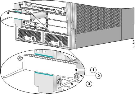
Removing and Installing the Front Cover
The front cover has release buttons on both sides that give you the flexibility to open it from either the left side or from the right side. Use the following procedures to remove and install the front cover.
Removing the Front Cover
To remove the front cover, grasp both sides of cover and press both release buttons simultaneously to release the door from its hinges (see Figure 5-1).
Installing the Front Cover
Use the following procedure to install the front cover.
Step 1 ![]() Align the hinges on each side of the cover with the hinges on each side of the chassis (see blowout in Figure 5-1)
Align the hinges on each side of the cover with the hinges on each side of the chassis (see blowout in Figure 5-1)
Step 2 ![]() Push the front cover until the hinges snap into place.
Push the front cover until the hinges snap into place.
Figure 5-1 Removing or Installing the Front Cover

|
|
Release buttons |
Removing and Replacing the Air Filters
The Cisco XR 12406 router is equipped with two user-serviceable air filters that remove dust drawn into the router by the blower module. You should examine the air filters once a month (or more often in dusty environments). If the filter appears dirty, you can either vacuum or replace it. If the filter appears worn or torn, dispose of it in a responsible manner and install a replacement air filter.
Use the following procedure to clean or replace the air filters.
Step 1 ![]() Open the spring-loaded air filter door on the right side of the chassis and remove an air filters by pulling the small tab on the edge of the filters (see Figure 5-2).
Open the spring-loaded air filter door on the right side of the chassis and remove an air filters by pulling the small tab on the edge of the filters (see Figure 5-2).
Step 2 ![]() Visually check the condition of the air filters.
Visually check the condition of the air filters.
•![]() If the filters appears dirty, you can either vacuum or replace them.
If the filters appears dirty, you can either vacuum or replace them.
Caution
•![]() If the filters appear worn or torn, dispose of them in a responsible manner and install replacement air filters.
If the filters appear worn or torn, dispose of them in a responsible manner and install replacement air filters.
Figure 5-2 Removing the Air Filters

|
|
Air filter door |
|
Air filters |
Step 3 ![]() Reinstall the air filter into the chassis noting the direction of the airflow arrows on the top of the air filter frame (Figure 5-3).
Reinstall the air filter into the chassis noting the direction of the airflow arrows on the top of the air filter frame (Figure 5-3).
Caution
Figure 5-3 Cisco XR 12404 Router Air Filter Direction of Air Flow

Removing and Replacing the Blower Module
Use the following procedure to remove and replace the blower module.
Step 1 ![]() Remove the blower module from the chassis (Figure 5-4):
Remove the blower module from the chassis (Figure 5-4):
a. ![]() Lift the blower module handle to its carrying position.
Lift the blower module handle to its carrying position.
b. ![]() Loosen the four captive screws on the blower module faceplate.
Loosen the four captive screws on the blower module faceplate.
c. ![]() Remove the blower module by grasping it on each side and pulling it straight back from the chassis.
Remove the blower module by grasping it on each side and pulling it straight back from the chassis.
Figure 5-4 Removing the Blower Module

|
|
Carrying handle |
|
Captive screws (2 on each side) |
Step 2 ![]() Install the new blower module (Figure 5-5):
Install the new blower module (Figure 5-5):
a. ![]() Position the alignment holes on the blower module with the guide pins at the top of the chassis and on the PDU at the bottom of the chassis.
Position the alignment holes on the blower module with the guide pins at the top of the chassis and on the PDU at the bottom of the chassis.
b. ![]() Slide the blower toward the chassis until it mates with the backplane connector.
Slide the blower toward the chassis until it mates with the backplane connector.
c. ![]() Tighten the four captive screws to secure the blower module to the chassis.
Tighten the four captive screws to secure the blower module to the chassis.
The (green) OK indicator should be on. If the OK indicator is not on, see the "Troubleshooting the Blower Installation" section.
d. ![]() Lower the blower module handle to its operating position.
Lower the blower module handle to its operating position.
Figure 5-5 Installing the Blower Module

|
|
Carrying handle |
|
Guide pins |
|
|
Captive screws (2 on each side) |
|
|
Troubleshooting the Blower Installation
Use the following procedure to troubleshoot the blower module if it is not operating properly after installation.
Step 1 ![]() Be sure the router is powered on and that all power cords are connected properly.
Be sure the router is powered on and that all power cords are connected properly.
Step 2 ![]() Loosen the four captive screws and reseat the blower module to the chassis. Retighten the captive screws to ensure the blower module is properly seated to the backplane connector.
Loosen the four captive screws and reseat the blower module to the chassis. Retighten the captive screws to ensure the blower module is properly seated to the backplane connector.
Step 3 ![]() Check the blower module status indicators:
Check the blower module status indicators:
•![]() OK (green)—This indicator should light as soon as the blower module is installed and receives power from the backplane connector. It indicates that the blower module is operating normally.
OK (green)—This indicator should light as soon as the blower module is installed and receives power from the backplane connector. It indicates that the blower module is operating normally.
•![]() Fail (red)—This indicator remains off during normal operation. If the indicator is on, the system has detected a fan failure or other fault in the blower module.
Fail (red)—This indicator remains off during normal operation. If the indicator is on, the system has detected a fan failure or other fault in the blower module.
–![]() If this indicator remains on and the blower module fans fail to operate normally after several attempts to reseat the blower module, replace the existing blower module with a spare.
If this indicator remains on and the blower module fans fail to operate normally after several attempts to reseat the blower module, replace the existing blower module with a spare.
–![]() If the spare blower module also fails, power off the router and contact a Cisco service representative for assistance.
If the spare blower module also fails, power off the router and contact a Cisco service representative for assistance.
Installation Guidelines
The Cisco XR 12406 router support online insertion and removal (OIR). If you are replacing a redundant power supply, you can remove and install the power supply while the system remains powered on without causing an electrical hazard or damage to the system. This feature enables you replace a power supply while the system maintains all routing information and ensures session preservation.
However, to maintain operational redundancy, proper cooling, and meet EMI compliance standards, you must have both working power supplies installed. When you remove a failed power supply with the router in operation, perform the replacement as quickly as possible. Make sure you have the tools and the replacement power supply ready before beginning the removal and installation procedure.
Removing and Replacing an AC Power Entry Module
Although an AC PEM supports OIR, in order to maintain operational redundancy, proper cooling, and meet EMI compliance standards, you must have both working power supplies installed. When you remove a failed power supply with the router in operation, perform the replacement as quickly as possible. Make sure you have the tools and the replacement power supply ready before beginning the removal and installation procedure.
Use the following procedure to remove and replace an AC PEM.
Step 1 ![]() Power off the faulty PEM (see item 3 in Figure 5-6).
Power off the faulty PEM (see item 3 in Figure 5-6).
Figure 5-6 AC Power Supply Components

|
|
AC PEM |
|
Captive screws/release levers |
|
|
Handle |
|
AC input/DC output status indicators |
|
|
Power On/Off switch |
|
|
Step 2 ![]() Unplug the power supply cord from its AC outlet.
Unplug the power supply cord from its AC outlet.
Step 3 ![]() Power off the circuit breaker assigned to that AC outlet.
Power off the circuit breaker assigned to that AC outlet.
Step 4 ![]() Remove the PEM from the chassis (Figure 5-7):
Remove the PEM from the chassis (Figure 5-7):
a. ![]() Loosen the captive screw on each ejector lever.
Loosen the captive screw on each ejector lever.
b. ![]() Pivot open the levers to eject the power supply.
Pivot open the levers to eject the power supply.
c. ![]() Slide the power supply out of its bay while supporting it with your other hand.
Slide the power supply out of its bay while supporting it with your other hand.

Warning ![]() The power supply weighs approximately 14 lb (6.35 kg). Use two hands to remove the power supply.
The power supply weighs approximately 14 lb (6.35 kg). Use two hands to remove the power supply.
Figure 5-7 Releasing the AC Power Supply

Step 5 ![]() Install the new power supply (Figure 5-8):
Install the new power supply (Figure 5-8):
a. ![]() Slide the power supply into the bay until it mates with its backplane connector.
Slide the power supply into the bay until it mates with its backplane connector.
b. ![]() Close the ejector levers and tighten the captive screws to securely seat the power supply to the backplane connector.
Close the ejector levers and tighten the captive screws to securely seat the power supply to the backplane connector.
Figure 5-8 Seating the AC Power Supply

Step 6 ![]() Plug the power supply cable into its AC outlet.
Plug the power supply cable into its AC outlet.
Step 7 ![]() Power on the circuit breaker to that AC outlet.
Power on the circuit breaker to that AC outlet.
Step 8 ![]() Set the power switch to the On (1) position.
Set the power switch to the On (1) position.
The AC Input and DC Output power indicators on the front of the power supply should be on. If the indicators do not are not on, see the "Troubleshooting the AC Power Entry Module Installation" section.
Troubleshooting the AC Power Entry Module Installation
Use the following procedure to troubleshoot the AC PEM if it is not operating properly after installation.
Step 1 ![]() Reseat the PEM and make sure that the:
Reseat the PEM and make sure that the:
–![]() Captive screws on the ejector levers are tightened securely.
Captive screws on the ejector levers are tightened securely.
–![]() Power switch is set to the On (1) position.
Power switch is set to the On (1) position.
Step 2 ![]() Ensure that the router is powered on and that all power cords are connected properly. Make sure that the:
Ensure that the router is powered on and that all power cords are connected properly. Make sure that the:
•![]() Power cords on the back of the chassis are secured to the PDU with their retention clips.
Power cords on the back of the chassis are secured to the PDU with their retention clips.
•![]() Power cords at the power source end are connected to a dedicated AC power outlet.
Power cords at the power source end are connected to a dedicated AC power outlet.
–![]() Each AC power supply operating in the nominal range of 200 to 240 VAC requires a minimum service of 20 A, North America (or 13 A, international).
Each AC power supply operating in the nominal range of 200 to 240 VAC requires a minimum service of 20 A, North America (or 13 A, international).
•![]() Source AC circuit breaker is switched on.
Source AC circuit breaker is switched on.
Step 3 ![]() Check the power supply status indicators:
Check the power supply status indicators:
•![]() AC Input (green)—Indicates that the power supply is operating normally, and the source AC voltage is within the nominal operating range of 200 VAC to 240 VAC. This indicator lights when the power supply switch is set to the On (1) position.
AC Input (green)—Indicates that the power supply is operating normally, and the source AC voltage is within the nominal operating range of 200 VAC to 240 VAC. This indicator lights when the power supply switch is set to the On (1) position.
–![]() If the AC Input power indicator remains off after checking all of the power sources, replace the power supply with a spare.
If the AC Input power indicator remains off after checking all of the power sources, replace the power supply with a spare.
–![]() If the spare power supply does not work, replace the PDU.
If the spare power supply does not work, replace the PDU.
•![]() DC Output (green)—Indicates that the power supply is operating normally, and the output DC voltage is within the nominal operating range of -48 VDC to -60 VDC. This indicator lights when the power switch is set to the On (1) position.
DC Output (green)—Indicates that the power supply is operating normally, and the output DC voltage is within the nominal operating range of -48 VDC to -60 VDC. This indicator lights when the power switch is set to the On (1) position.
If the indicator is off, toggle the power switch off and then on. If the indicator remains off after several attempts to power it on, replace the power supply with a spare.
Removing and Replacing an AC PDU
The AC PDU does not support online insertion and removal (OIR) and cannot be replaced while the system is operating. You must power off the router before replacing the PDU.
Use the following procedure to remove and replace an AC PDU.
Step 1 ![]() Power off both PEMs by setting the power switches to the off (0) position.
Power off both PEMs by setting the power switches to the off (0) position.
Step 2 ![]() Unplug the power supply cords from their AC outlets.
Unplug the power supply cords from their AC outlets.
Step 3 ![]() Power off the circuit breakers assigned to the AC outlets.
Power off the circuit breakers assigned to the AC outlets.
Step 4 ![]() Loosen the captive screw on each ejector lever and pivot the levers open to unseat the power supply from its PDU connector (Figure 5-9).
Loosen the captive screw on each ejector lever and pivot the levers open to unseat the power supply from its PDU connector (Figure 5-9).
•![]() It is not necessary to remove the power supply from its bay.
It is not necessary to remove the power supply from its bay.
•![]() Repeat this step for the second power supply.
Repeat this step for the second power supply.
Figure 5-9 Unseating the AC Power Supply
Step 5 ![]() Release the retention clip and disconnect each power supply cord from the PDU (items 2 and 3 in Figure 5-10).
Release the retention clip and disconnect each power supply cord from the PDU (items 2 and 3 in Figure 5-10).
Figure 5-10 AC Power Distribution Unit

|
|
Captive screw |
|
AC power distribution unit |
|
|
AC power cord connector/retention clip (A) |
|
Guide pin |
|
|
AC power cord connector/retention clip (B) |
|
Blower module connector |
Step 6 ![]() Remove the blower module (Figure 5-11):
Remove the blower module (Figure 5-11):
a. ![]() Lift the blower module handle to its raised (carrying) position.
Lift the blower module handle to its raised (carrying) position.
b. ![]() Loosen the (4) captive screws on the blower module.
Loosen the (4) captive screws on the blower module.
c. ![]() Remove the blower module by grasping it on each side and pulling it straight back from the chassis.
Remove the blower module by grasping it on each side and pulling it straight back from the chassis.
Figure 5-11 Removing the Blower Module

Step 7 ![]() Remove the PDU from the chassis (Figure 5-12):
Remove the PDU from the chassis (Figure 5-12):
a. ![]() Loosen the (4) captive screws on the PDU.
Loosen the (4) captive screws on the PDU.
b. ![]() Grasp the PDU and pull it out slightly.
Grasp the PDU and pull it out slightly.
c. ![]() Move the PDU to the left and pivot the right side through the opening to remove the PDU from the chassis opening.
Move the PDU to the left and pivot the right side through the opening to remove the PDU from the chassis opening.

Note ![]() Tilting the PDU at a slight angle makes it easier to remove it from the chassis.
Tilting the PDU at a slight angle makes it easier to remove it from the chassis.
Figure 5-12 Removing the AC PDU

Step 8 ![]() Install the new PDU and tighten its (4) captive screws to secure it to the chassis.
Install the new PDU and tighten its (4) captive screws to secure it to the chassis.
Step 9 ![]() Install the blower module (Figure 5-13):
Install the blower module (Figure 5-13):
a. ![]() Position the alignment holes on the blower module with the guide pins on the chassis and PDU.
Position the alignment holes on the blower module with the guide pins on the chassis and PDU.
b. ![]() Slide the blower over the guide pins toward the chassis until it mates with the PDU connector.
Slide the blower over the guide pins toward the chassis until it mates with the PDU connector.
c. ![]() Tighten the (4) captive screws to secure the blower module to the chassis.
Tighten the (4) captive screws to secure the blower module to the chassis.
d. ![]() Lower the carrying handle to its operating position.
Lower the carrying handle to its operating position.
Figure 5-13 Installing the Blower Module
Step 10 ![]() Reconnect the power cords to the PDU and secure them using their retention clips.
Reconnect the power cords to the PDU and secure them using their retention clips.
Step 11 ![]() Plug the power cords into their AC outlets.
Plug the power cords into their AC outlets.
Step 12 ![]() Power on the circuit breakers assigned to the AC outlets.
Power on the circuit breakers assigned to the AC outlets.
Step 13 ![]() Reinstall the power supplies (Figure 5-14):
Reinstall the power supplies (Figure 5-14):
a. ![]() Push the power supply into its bay until it mates with its PDU connector.
Push the power supply into its bay until it mates with its PDU connector.
b. ![]() Close the ejector levers and tighten the captive screws to securely seat the power supply to the chassis.
Close the ejector levers and tighten the captive screws to securely seat the power supply to the chassis.
c. ![]() Repeat steps a. and b. for the second power supply.
Repeat steps a. and b. for the second power supply.
Figure 5-14 Seating the AC Power Supply
Step 14 ![]() Set the power switch on both power supplies to the on (1) position.
Set the power switch on both power supplies to the on (1) position.
The AC Input Power and DC Output Power indicators on the power supplies should be on. If the indicators do are not on, see the "Troubleshooting the AC Power Entry Module Installation" section.
Removing and Replacing a DC PEM
Although a DC PEM supports OIR, in order to maintain operational redundancy, proper cooling, and meet EMI compliance standards, you must have both working power supplies installed. When you remove a failed power supply with the router in operation, perform the replacement as quickly as possible. Make sure you have the tools and the replacement power supply ready before beginning the removal and installation procedure.
Use the following procedure to remove and replace a DC PEM.
Step 1 ![]() Power off the faulty PEM (item 3 in Figure 5-15).
Power off the faulty PEM (item 3 in Figure 5-15).
Figure 5-15 DC Power Entry Module Components

|
|
DC PEM |
|
Captive screws/release levers |
|
|
Handle |
|
Cooling fan |
|
|
Power On/Off switch |
|
AC input/DC output/miswire status indicators |
Step 2 ![]() Power off the circuit breaker assigned to the power supply.
Power off the circuit breaker assigned to the power supply.
Step 3 ![]() Remove the power supply from the chassis (Figure 5-16):
Remove the power supply from the chassis (Figure 5-16):
a. ![]() Loosen the captive screw on each ejector lever.
Loosen the captive screw on each ejector lever.
b. ![]() Pivot the levers open to release the power supply from its bay.
Pivot the levers open to release the power supply from its bay.
c. ![]() Slide the power supply out of its bay while supporting it with your other hand.
Slide the power supply out of its bay while supporting it with your other hand.
Warning ![]() The power supply weighs approximately 10 lb (4.5 kg). Use two hands to remove the power supply.
The power supply weighs approximately 10 lb (4.5 kg). Use two hands to remove the power supply.
Figure 5-16 Releasing the DC Power Supply

Step 4 ![]() Install the new power supply:
Install the new power supply:
a. ![]() Slide the power supply into the bay until it mates with its backplane connector.
Slide the power supply into the bay until it mates with its backplane connector.
b. ![]() Close the ejector levers and tighten the captive screws to securely seat the power supply to the backplane connector (Figure 5-17).
Close the ejector levers and tighten the captive screws to securely seat the power supply to the backplane connector (Figure 5-17).
Figure 5-17 Seating the DC Power Supply

Step 5 ![]() Power on the circuit breaker.
Power on the circuit breaker.
Step 6 ![]() Power on the PEM.
Power on the PEM.
The AC Input and DC Output power indicators on the front of the power supply should be on. If the indicators do are not on, or the Miswire indicator is on, see the "Troubleshooting the DC Power Supply Installation" section.
Troubleshooting the DC Power Supply Installation
Use the following procedure to troubleshoot the DC power supply if it is not operating properly after installation.
Step 1 ![]() Make sure the power supply is seated properly:
Make sure the power supply is seated properly:
•![]() Eject and reseat the power supply. Make sure that the:
Eject and reseat the power supply. Make sure that the:
–![]() Captive screw on the ejector lever are tightened securely.
Captive screw on the ejector lever are tightened securely.
–![]() Power switch is set to the on (1) position.
Power switch is set to the on (1) position.
Step 2 ![]() If the Input OK and Output OK LEDs are off, or if the Output Fail LED is on, make sure that the:
If the Input OK and Output OK LEDs are off, or if the Output Fail LED is on, make sure that the:
•![]() Power switch is set to the on (1) position.
Power switch is set to the on (1) position.
•![]() Power leads are securely connected to the power connector block on the PDU.
Power leads are securely connected to the power connector block on the PDU.
•![]() Power cables are securely connected at the DC source connection.
Power cables are securely connected at the DC source connection.
•![]() The source DC circuit breaker is turned on.
The source DC circuit breaker is turned on.
Step 3 ![]() Check the power supply status indicators:
Check the power supply status indicators:
•![]() Output OK (green)—Indicates that the PEM is operating normally, and the source DC output voltage is within the nominal operating range of -48 to -60 VDC. This indicator should light when the power switch is set to the On (1) position.
Output OK (green)—Indicates that the PEM is operating normally, and the source DC output voltage is within the nominal operating range of -48 to -60 VDC. This indicator should light when the power switch is set to the On (1) position.
If the indicator is off, toggle the power switch off and then on. If the indicator remains off after several attempts to power it on, replace the power supply with a spare.
•![]() Input OK (green)—Indicates that the power supply is operating normally, and the source DC input voltage is within the nominal operating range of -40.5VDC to -75VDC. This indicator should light when the power supply switch is set to the On (1) position.
Input OK (green)—Indicates that the power supply is operating normally, and the source DC input voltage is within the nominal operating range of -40.5VDC to -75VDC. This indicator should light when the power supply switch is set to the On (1) position.
–![]() If the Input OK indicator remains off after checking all of the power sources, replace the power supply with a spare.
If the Input OK indicator remains off after checking all of the power sources, replace the power supply with a spare.
–![]() If the spare power supply does not work, replace the PDU.
If the spare power supply does not work, replace the PDU.
•![]() Miswire (amber)—Indicates the input wiring is incorrect at the PDU power connection block.
Miswire (amber)—Indicates the input wiring is incorrect at the PDU power connection block.
Correct wiring to the DC power connector block (see Figure 5-24).
Removing and Replacing a DC PDU
The DC PDU does not support online insertion and removal (OIR) and cannot be replaced while the system is operating. You must power off the router before replacing the PDU.
Use the following procedure to remove and replace a DC PDU.
Step 1 ![]() Power off both PEMs (item 3in Figure 5-18).
Power off both PEMs (item 3in Figure 5-18).
Figure 5-18 DC Power Entry Module Components
|
|
DC PEM |
|
Captive screws/release levers |
|
|
Handle |
|
Cooling fan |
|
|
Power On/Off switch |
|
AC input/DC output/miswire status indicators |
Step 2 ![]() Power off the circuit breakers assigned to the PEMs.
Power off the circuit breakers assigned to the PEMs.
Step 3 ![]() Loosen the captive screw on each ejector lever and pivot the levers open to unseat the power supply from its PDU connector (Figure 5-19).
Loosen the captive screw on each ejector lever and pivot the levers open to unseat the power supply from its PDU connector (Figure 5-19).
•![]() It is not necessary to remove the power supply from its bay.
It is not necessary to remove the power supply from its bay.
•![]() Repeat this step for the second power supply.
Repeat this step for the second power supply.
Figure 5-19 Unseating the DC Power Supply
Step 4 ![]() Remove the blower module (Figure 5-20):
Remove the blower module (Figure 5-20):
a. ![]() Lift the blower module handle to its raised (carrying) position.
Lift the blower module handle to its raised (carrying) position.
b. ![]() Loosen the (4) captive screws on the blower module.
Loosen the (4) captive screws on the blower module.
c. ![]() Remove the blower module by grasping it on each side and pulling it straight back from the chassis.
Remove the blower module by grasping it on each side and pulling it straight back from the chassis.
Figure 5-20 Removing the Blower Module
Step 5 ![]() Disconnect the DC power leads from the PDU power connector blocks in the following order (Figure 5-21):
Disconnect the DC power leads from the PDU power connector blocks in the following order (Figure 5-21):
a. ![]() Negative lead from the top port.
Negative lead from the top port.
b. ![]() Positive lead from the middle port.
Positive lead from the middle port.
c. ![]() Ground lead from the bottom port.
Ground lead from the bottom port.
d. ![]() Repeat these steps for the second power connector block.
Repeat these steps for the second power connector block.
Warning ![]() To prevent injury and damage to the equipment, always remove the source DC power leads and ground from the power shelf terminals in the following order: (a) negative (-), (b) positive (+), (c) ground.
To prevent injury and damage to the equipment, always remove the source DC power leads and ground from the power shelf terminals in the following order: (a) negative (-), (b) positive (+), (c) ground.
Figure 5-21 Disconnecting the DC Power Leads

|
|
Negative terminal port |
|
Ground terminal port |
|
|
Positive terminal port |
|
Terminal port connector screws |
Step 6 ![]() Remove the PDU from the chassis (Figure 5-22):
Remove the PDU from the chassis (Figure 5-22):
a. ![]() Loosen the (4) captive screws on the PDU.
Loosen the (4) captive screws on the PDU.
b. ![]() Grasp the PDU and pull it out slightly.
Grasp the PDU and pull it out slightly.
c. ![]() Move the PDU to the left and pivot the right side through the opening to remove the PDU from the chassis.
Move the PDU to the left and pivot the right side through the opening to remove the PDU from the chassis.
Note ![]() Tilting the PDU at a slight angle makes it easier to remove it from the chassis.
Tilting the PDU at a slight angle makes it easier to remove it from the chassis.
Figure 5-22 Removing the DC PDU

Step 7 ![]() Install the new PDU and tighten its (4) captive screws to secure it to the chassis.
Install the new PDU and tighten its (4) captive screws to secure it to the chassis.
Step 8 ![]() Install the blower module (Figure 5-23):
Install the blower module (Figure 5-23):
a. ![]() Position the alignment holes on the blower module with the guide pins on the chassis and PDU.
Position the alignment holes on the blower module with the guide pins on the chassis and PDU.
b. ![]() Slide the blower over the guide pins toward the chassis until it mates with the backplane connector.
Slide the blower over the guide pins toward the chassis until it mates with the backplane connector.
c. ![]() Tighten the (4) captive screws to secure the blower module to the chassis.
Tighten the (4) captive screws to secure the blower module to the chassis.
d. ![]() Lower the carrying handle to its operating position.
Lower the carrying handle to its operating position.
Figure 5-23 Installing the Blower Module
Step 9 ![]() Reconnect the DC power leads to each of the PDU power connector blocks in the following order (Figure 5-24):
Reconnect the DC power leads to each of the PDU power connector blocks in the following order (Figure 5-24):
a. ![]() Ground lead to the bottom port.
Ground lead to the bottom port.
b. ![]() Positive lead to the middle port.
Positive lead to the middle port.
c. ![]() Negative lead to the top port.
Negative lead to the top port.
d. ![]() Repeat these steps for the second power connector block.
Repeat these steps for the second power connector block.
Warning ![]() To prevent injury and damage to the equipment, always attach the ground and source DC power leads to the power block connector in the following order: (a) ground to ground, (b) positive (+) to positive (+), (c) negative (-) to negative (-).
To prevent injury and damage to the equipment, always attach the ground and source DC power leads to the power block connector in the following order: (a) ground to ground, (b) positive (+) to positive (+), (c) negative (-) to negative (-).
Figure 5-24 Disconnecting the DC Power Leads
|
|
Negative terminal port |
|
Ground terminal port |
|
|
Positive terminal port |
|
Terminal port connector screws |
Step 10 ![]() Reinstall the PEMs:
Reinstall the PEMs:
a. ![]() Slide each PEM into its bay until it mates with its PDU connector.
Slide each PEM into its bay until it mates with its PDU connector.
Caution
b. ![]() Close the ejector levers and tighten the captive screws to securely seat the power supply to the chassis (Figure 5-25).
Close the ejector levers and tighten the captive screws to securely seat the power supply to the chassis (Figure 5-25).
c. ![]() Repeat steps a. and b. for the second power supply.
Repeat steps a. and b. for the second power supply.
Figure 5-25 Seating a DC Power Supply
Step 11 ![]() Power on the circuit breakers assigned to the PEMs.
Power on the circuit breakers assigned to the PEMs.
Step 12 ![]() Power on the PEMs.
Power on the PEMs.
The Output Power OK and Input Power OK indicators on the power supplies should be on. If the indicators do are not on, see the "Troubleshooting the DC Power Supply Installation" section.
Troubleshooting the DC PDU Installation
Refer to Figure 5-26 and use the following procedure to troubleshoot the DC PDU installation.
Figure 5-26 DC Power Entry Module Components
|
|
DC PEM |
|
Captive screws/release levers |
|
|
Handle |
|
Cooling fan |
|
|
Power On/Off switch |
|
AC input/DC output/miswire status indicators |
Step 1 ![]() If the Input OK and Output OK LEDs are off, make sure that the:
If the Input OK and Output OK LEDs are off, make sure that the:
•![]() PEM is firmly seated in the bay and the captive screws are tightened securely.
PEM is firmly seated in the bay and the captive screws are tightened securely.
•![]() DC power source circuit breakers are switched on.
DC power source circuit breakers are switched on.
•![]() DC power cables are securely attached to the PDU terminal block.
DC power cables are securely attached to the PDU terminal block.
•![]() Power switch is set to the on (1) position.
Power switch is set to the on (1) position.
Step 2 ![]() If the amber MISWIRE LED is on, the wires on the power block are reversed.
If the amber MISWIRE LED is on, the wires on the power block are reversed.
a. ![]() Power off the PEMs and make sure the DC power source circuit breakers are switched off. Go to Step 9 of the installation procedure and reconnect the wires correctly to each of the power connector blocks.
Power off the PEMs and make sure the DC power source circuit breakers are switched off. Go to Step 9 of the installation procedure and reconnect the wires correctly to each of the power connector blocks.
b. ![]() Switch on the DC source power circuit breakers and power on the PEMs.
Switch on the DC source power circuit breakers and power on the PEMs.
If the problem still exists, replace the PEM.
If replacing the PEM does not correct the problem, contact a Cisco service representative for assistance.
Removing and Replacing an RP or a Line Card
Line cards can occupy any slot, 0 (the top slot) through 4, in the RP and line card cage (Figure 5-27). The Cisco XR 12406 router is configured with the RP in slot 5 (the bottom slot). A redundant RP can be installed in any slot, but requires a line card spacer to comply with EMI emission standards.
Cisco XR 12406 router line cards support OIR, so they can be removed and installed while the router remains powered up. RPs also support OIR, but are hot-swappable only when the system is equipped with two RPs.
Additional line card information can be found in the installation and configuration documentation for each type of line card.
Figure 5-27 Cisco XR 12406 Router Card Cage Slot Locations

Use the following procedure to remove and replace an RP or line card.
Step 1 ![]() Identify the RP or line card to be replaced and write down the following information:
Identify the RP or line card to be replaced and write down the following information:
•![]() The RP cable connections on the RP.
The RP cable connections on the RP.
•![]() The number and type of RP or line card, so that you will know the location of the card when you re-install it or the replacement, in the card cage.
The number and type of RP or line card, so that you will know the location of the card when you re-install it or the replacement, in the card cage.
•![]() The network interface cable connection ports, on the RP or line card.
The network interface cable connection ports, on the RP or line card.
Step 2 ![]() On cards with multiple ports, start with the left port on the card and disconnect the interface cable connectors from each of the ports.
On cards with multiple ports, start with the left port on the card and disconnect the interface cable connectors from each of the ports.
Step 3 ![]() After all the interface cables are disconnected, loosen the two captive screws on the cable-management bracket and pull the bracket away from the card.
After all the interface cables are disconnected, loosen the two captive screws on the cable-management bracket and pull the bracket away from the card.
Step 4 ![]() Loosen the two ejector lever captive screws at each end of the line card faceplate.
Loosen the two ejector lever captive screws at each end of the line card faceplate.
Step 5 ![]() Simultaneously pivot the ejector levers away from each other to unseat the card from the backplane connector (Figure 5-28).
Simultaneously pivot the ejector levers away from each other to unseat the card from the backplane connector (Figure 5-28).
Figure 5-28 Removing an RP or Line Card from the Card Cage

Step 6 ![]() Grasp the edges of the card carrier with both hand to support it and remove the card.
Grasp the edges of the card carrier with both hand to support it and remove the card.
Caution
•![]() Immediately place the RP or line card in an antistatic bag to protect it against ESD and to prevent dust from getting to the fiber-optic connectors on fiber-optic line cards.
Immediately place the RP or line card in an antistatic bag to protect it against ESD and to prevent dust from getting to the fiber-optic connectors on fiber-optic line cards.
•![]() If you plan to return the defective unit to the factory, repackage it in the shipping container you received with the replacement RP or line card.
If you plan to return the defective unit to the factory, repackage it in the shipping container you received with the replacement RP or line card.
Step 7 ![]() Remove the RP or line card from its shipping package and antistatic bag.
Remove the RP or line card from its shipping package and antistatic bag.
Caution
Step 8 ![]() Seat the RP or line card:
Seat the RP or line card:
a. ![]() Set both edges of the RP or line card into the card slot and partially slide the card into the chassis.
Set both edges of the RP or line card into the card slot and partially slide the card into the chassis.
b. ![]() Pivot the ejector levers away from each other by rotating each ejector lever outward away from the faceplate.
Pivot the ejector levers away from each other by rotating each ejector lever outward away from the faceplate.
c. ![]() Continue sliding the card into the slot until the ejector levers make contact with the front of the card cage, then stop.
Continue sliding the card into the slot until the ejector levers make contact with the front of the card cage, then stop.
d. ![]() Seat the card by grasping each ejector levers and simultaneously pivot them toward the card faceplate.
Seat the card by grasping each ejector levers and simultaneously pivot them toward the card faceplate.
Note ![]() The line card will not boot properly if not fully seated.
The line card will not boot properly if not fully seated.
Step 9 ![]() Tighten the captive screws on the card.
Tighten the captive screws on the card.
Note ![]() The card captive screws must be tightened to meet EMI specification standards.
The card captive screws must be tightened to meet EMI specification standards.
Repeat Step 1 through Step 9 for any additional replacement RPs or line cards, and then proceed to the next section.
Attaching the Cable-Management Bracket and Connecting Cables
The Cisco XR 12406 router line cards use cable-management brackets to:
•![]() Organizing the network interface cables
Organizing the network interface cables
•![]() Keeping the network interface cables out of the way
Keeping the network interface cables out of the way
•![]() Positioning connectors at their respective ports on the line card faceplate
Positioning connectors at their respective ports on the line card faceplate
•![]() Keeping the cables free of sharp bends (excessive bending in a network interface cable can cause performance degradation)
Keeping the cables free of sharp bends (excessive bending in a network interface cable can cause performance degradation)
When you install a new RP or line card, you need to attach the line card cable-management bracket to the faceplate of the card before connecting the cables. The type of cable-management bracket used by a line card is determined by the card type and the number of network interface ports it has.
Use the following procedure to attach the cable-management bracket and cables to a line card.
Step 1 ![]() Orient the top of the cable-management bracket with the top of the line card faceplate (the end opposite the two four-character alphanumeric displays.)
Orient the top of the cable-management bracket with the top of the line card faceplate (the end opposite the two four-character alphanumeric displays.)
Step 2 ![]() Align the two captive screws on the bracket with the threaded insert holes near the ejector levers on each end of the line card faceplate and finger-tighten the screws.
Align the two captive screws on the bracket with the threaded insert holes near the ejector levers on each end of the line card faceplate and finger-tighten the screws.
Step 3 ![]() Use a flat-blade screwdriver to secure the two captive screws.
Use a flat-blade screwdriver to secure the two captive screws.
Caution
Figure 5-29 Line Card Cable-Management Bracket

Step 4 ![]() Repeat steps 1 through 3 for any remaining line cards.
Repeat steps 1 through 3 for any remaining line cards.
Step 5 ![]() Attach an appropriate number of velcro straps through the slots in the cable-management bracket to support the network interface cables (Figure 5-30).
Attach an appropriate number of velcro straps through the slots in the cable-management bracket to support the network interface cables (Figure 5-30).
a. ![]() Pull the small end of the velcro strap through the slot in the cable-management bracket.
Pull the small end of the velcro strap through the slot in the cable-management bracket.
b. ![]() Insert the small end of the velcro strap into the slot in the wide end of the velcro strap.
Insert the small end of the velcro strap into the slot in the wide end of the velcro strap.
c. ![]() Pull the small end through the velcro strap slot to secure it to the cable- management bracket.
Pull the small end through the velcro strap slot to secure it to the cable- management bracket.
Figure 5-30 Line Card Cable-Management Brackets with Velcro Straps

Step 6 ![]() Proceeding from the left port on the line card to the right port (on line cards with multiple ports), identify the network interface cable for the line card port and insert the cable connector into the line card port (see Figure 5-30).
Proceeding from the left port on the line card to the right port (on line cards with multiple ports), identify the network interface cable for the line card port and insert the cable connector into the line card port (see Figure 5-30).
a. ![]() Align the interface cable with the cable-management bracket.
Align the interface cable with the cable-management bracket.
b. ![]() Repeat for the remainder of the interface cables for this line card.
Repeat for the remainder of the interface cables for this line card.
Note ![]() Carefully adjust the interface cables in the cable-management bracket to prevent any kinks or sharp bends in the interface cables. Kinks and sharp bends can destroy or degrade the ability of the optical fiber to propagate the signal-encoded beam of light accurately from one end of the cable to the other. Also, allow adequate strain relief in the interface cables.
Carefully adjust the interface cables in the cable-management bracket to prevent any kinks or sharp bends in the interface cables. Kinks and sharp bends can destroy or degrade the ability of the optical fiber to propagate the signal-encoded beam of light accurately from one end of the cable to the other. Also, allow adequate strain relief in the interface cables.
Step 7 ![]() Secure the interface cables to the cable-management bracket by wrapping the velcro straps around them (see Figure 5-30).
Secure the interface cables to the cable-management bracket by wrapping the velcro straps around them (see Figure 5-30).
Note ![]() Do not wrap the velcro straps too tightly.
Do not wrap the velcro straps too tightly.
Removing and Installing a Clock and Scheduler Card, Switch Fabric Card, or Alarm Card
The Cisco XR 12406 router is based on a 10-Gbps switch fabric, where each SFC or CSC provides a 10-Gbps full-duplex connection to each line card in the system. The 10-Gbps switch fabric consists of the Clock Scheduler Card and the Switch Fabric Card. The chassis has slots for two CSCs, three SFCs, and two alarm cards (Figure 5-31).
Figure 5-31 CSC, SFC, and Alarm Card Slot Locations

Removing and Replacing a Clock Scheduler Card
If a router is not configured with redundant CSCs, it has one CSC installed in either of the CSC slots, and has a CSC blank filler installed in the second CSC slot.
Use the following procedure to remove and replace a CSC.
Step 1 ![]() Loosen the two captive screws on each side of the CSC (Figure 5-32).
Loosen the two captive screws on each side of the CSC (Figure 5-32).
Figure 5-32 Removing and Installing a Clock Scheduler Card
|
|
CSC |
|
Ejector lever (2) |
|
|
Captive screw (2) |
|
|
Step 2 ![]() Grasp the card ejector levers and pivot them away from the CSC faceplate (see Figure 5-32).
Grasp the card ejector levers and pivot them away from the CSC faceplate (see Figure 5-32).
Step 3 ![]() Slide the CSC halfway out of the slot, then stop.
Slide the CSC halfway out of the slot, then stop.
Step 4 ![]() Touching only the metal card carrier, use your free hand to support the bottom of the CSC and slide the card completely out of the chassis.
Touching only the metal card carrier, use your free hand to support the bottom of the CSC and slide the card completely out of the chassis.
•![]() Always place the CSC directly into an antistatic bag or other ESD-preventive container.
Always place the CSC directly into an antistatic bag or other ESD-preventive container.
•![]() If you plan to return the defective CSC to the factory, repackage it in the shipping container you received with the replacement card.
If you plan to return the defective CSC to the factory, repackage it in the shipping container you received with the replacement card.
Step 5 ![]() Set both edges of the CSC carrier into the card slot carrier alignment grooves on either side of the CSC slot and slide the card halfway into the chassis.
Set both edges of the CSC carrier into the card slot carrier alignment grooves on either side of the CSC slot and slide the card halfway into the chassis.
Step 6 ![]() Pivot the ejector levers outward away from the faceplate.
Pivot the ejector levers outward away from the faceplate.
Step 7 ![]() Slide the card into the CSC slot until the ejector levers make contact with the front of the card cage, then stop.
Slide the card into the CSC slot until the ejector levers make contact with the front of the card cage, then stop.
Step 8 ![]() Pivot the ejector levers toward the faceplate until the connector properly seats in the backplane.
Pivot the ejector levers toward the faceplate until the connector properly seats in the backplane.
Step 9 ![]() Tighten the two captive screws.
Tighten the two captive screws.
Caution
Verifying the Installation of the Clock Scheduler Card
To verify router operation after installing a replacement CSC, see the "Verifying the Installation of Alarm Cards, Clock Scheduler Cards, and Switch Fabric Cards" section.
Removing and Replacing a Switch Fabric Card
Use the following procedure to remove and replace a SFC.
Step 1 ![]() Loosen the captive screw on each side of the SFC faceplate (Figure 5-33).
Loosen the captive screw on each side of the SFC faceplate (Figure 5-33).
Figure 5-33 Removing and Installing a Switch Fabric Card

|
|
SFC |
|
Ejector lever (2) |
|
|
Captive screw (2) |
— |
|
Step 2 ![]() Grasp the card ejector levers and pivot them away from the SFC faceplate
Grasp the card ejector levers and pivot them away from the SFC faceplate
(see Figure 5-33).
Step 3 ![]() Slide the SFC halfway out of the slot, then stop.
Slide the SFC halfway out of the slot, then stop.
Step 4 ![]() Touching only the metal card carrier, use your free hand to support the bottom of the SFC and slide the card completely out of the chassis.
Touching only the metal card carrier, use your free hand to support the bottom of the SFC and slide the card completely out of the chassis.
•![]() Always place the SFC directly into an antistatic bag or other ESD-preventive container.
Always place the SFC directly into an antistatic bag or other ESD-preventive container.
•![]() If you plan to return the defective SFC to the factory, repackage it in the shipping container you received with the replacement card.
If you plan to return the defective SFC to the factory, repackage it in the shipping container you received with the replacement card.
Step 5 ![]() Set both edges of the SFC carrier into the card slot carrier alignment grooves on either side of the SFC slot and slide the card halfway into the chassis.
Set both edges of the SFC carrier into the card slot carrier alignment grooves on either side of the SFC slot and slide the card halfway into the chassis.
Step 6 ![]() Pivot the ejector levers outward away from the faceplate.
Pivot the ejector levers outward away from the faceplate.
Step 7 ![]() Slide the card into the SFC slot until the ejector levers make contact with the front of the card cage, then stop.
Slide the card into the SFC slot until the ejector levers make contact with the front of the card cage, then stop.
Step 8 ![]() Pivot the ejector levers toward the faceplate until the connector properly seats in the backplane.
Pivot the ejector levers toward the faceplate until the connector properly seats in the backplane.
Step 9 ![]() Tighten the two captive screws.
Tighten the two captive screws.
Caution
Verifying the Installation of the Switch Fabric Card
To verify router operation after installing a replacement SFC, see the "Verifying the Installation of Alarm Cards, Clock Scheduler Cards, and Switch Fabric Cards" section.
Removing and Replacing an Alarm Card
Use the following procedure to remove and replace an alarm card.
Note ![]() The alarm cards support OIR, so you can remove and install an alarm card while the system remains powered on.
The alarm cards support OIR, so you can remove and install an alarm card while the system remains powered on.
Step 1 ![]() Loosen the captive screw on each side of the alarm card.
Loosen the captive screw on each side of the alarm card.
Figure 5-34 Removing and Installing an Alarm Card

|
|
Alarm card |
|
Captive screw (2) |
Step 2 ![]() Grasp the handle on the front of the alarm card and slide the alarm card halfway out of the slot, then stop.
Grasp the handle on the front of the alarm card and slide the alarm card halfway out of the slot, then stop.
Step 3 ![]() Touching only the metal card carrier, use your free hand to support the bottom of the alarm card and slide the card completely out of the chassis.
Touching only the metal card carrier, use your free hand to support the bottom of the alarm card and slide the card completely out of the chassis.
•![]() Always place the alarm card directly into an antistatic bag or other ESD-preventive container.
Always place the alarm card directly into an antistatic bag or other ESD-preventive container.
•![]() If you plan to return the defective alarm card to the factory, repackage it in the shipping container you received with the replacement card.
If you plan to return the defective alarm card to the factory, repackage it in the shipping container you received with the replacement card.
Step 4 ![]() Set both edges of the alarm card carrier into the card slot carrier alignment grooves on either side of the alarm card slot and slide the card into the chassis until its connector makes contact with the backplane, then stop.
Set both edges of the alarm card carrier into the card slot carrier alignment grooves on either side of the alarm card slot and slide the card into the chassis until its connector makes contact with the backplane, then stop.
Step 5 ![]() Push the alarm card firmly to seat it in the backplane.
Push the alarm card firmly to seat it in the backplane.
Step 6 ![]() Tighten the two alarm card captive screws.
Tighten the two alarm card captive screws.
Caution
Verifying the Installation of the Alarm Card
To verify router operation after installing a replacement alarm card, see the "Verifying the Installation of Alarm Cards, Clock Scheduler Cards, and Switch Fabric Cards" section.
Verifying the Installation of Alarm Cards, Clock Scheduler Cards, and Switch Fabric Cards
To verify proper router operation after installing a replacement CSC or SFC, you can visually check the LEDs on the two alarm cards.
Figure 5-35 shows the location of the alarm card LEDs.
Figure 5-35 Alarm Card LEDs

|
|
MBus status LED |
|
Critical alarm LED |
|
|
CSC status LEDs (two) |
|
Major alarm LED |
|
|
SFC status LEDs (three) |
|
Minor alarm LED |
The following LED conditions are displayed when the system is operating properly:
Note ![]() Green = Enabled, amber = Fail
Green = Enabled, amber = Fail
•![]() The following green LEDs are normally on:
The following green LEDs are normally on:
–![]() The MBUS status LED
The MBUS status LED
–![]() Two CSC status LEDs
Two CSC status LEDs
–![]() Three SFC status LEDs
Three SFC status LEDs
•![]() The following amber LEDs are normally off:
The following amber LEDs are normally off:
–![]() The MBUS status LED
The MBUS status LED
–![]() Two CSC status LED
Two CSC status LED
–![]() Three SFC status LEDs
Three SFC status LEDs
•![]() The three amber router alarm (Critical, Major, Minor) LEDs are normally off.
The three amber router alarm (Critical, Major, Minor) LEDs are normally off.
See the "Troubleshooting the Processor Subsystem" section on page 4-13 if the alarm cards indicate an error condition.
Upgrading the RP and Line Card Memory
To upgrade the RP and line card memory, refer to the Cisco 12000 Series Router Memory Replacement Instructions.
This publication contains the latest information about memory requirements and replacement procedures for the Cisco XR 12406 router RP and line cards. Consult this publication before replacing memory on your RP or line card, or adding memory to your RP or line card.
You can find Cisco XR 12000 Series Router memory replacement instructions at Cisco.com.
 Feedback