- Preface
- Introduction to Cisco IOS XR Software
- Bringing Up the Cisco IOS XR Software on a Standalone Router
- Configuring General Router Features
- Configuring Additional Router Features
- CLI Tips, Techniques, and Shortcuts
- Troubleshooting the Cisco IOS XR Software
- Understanding Regular Expressions, Special Characters, and Patterns
- Glossary
- Index
Cisco IOS XR Getting Started Guide for the Cisco XR 12000 Series Router, Release 4.3.x
Bias-Free Language
The documentation set for this product strives to use bias-free language. For the purposes of this documentation set, bias-free is defined as language that does not imply discrimination based on age, disability, gender, racial identity, ethnic identity, sexual orientation, socioeconomic status, and intersectionality. Exceptions may be present in the documentation due to language that is hardcoded in the user interfaces of the product software, language used based on RFP documentation, or language that is used by a referenced third-party product. Learn more about how Cisco is using Inclusive Language.
- Updated:
- April 29, 2013
Chapter: Introduction to Cisco IOS XR Software
Introduction to Cisco IOS XR Software
This chapter introduces the routers that support Cisco IOS XR software. It also introduces router concepts, features, and user interfaces.
Contents
•![]() Supported Standalone System Configurations
Supported Standalone System Configurations
•![]() Cisco XR 12000 Series Router Overview
Cisco XR 12000 Series Router Overview
•![]() Selecting and Identifying the Designated Shelf Controller
Selecting and Identifying the Designated Shelf Controller
•![]() Connecting to the Router Through the Console Port
Connecting to the Router Through the Console Port
Feature History - Cisco XR 12000 Series Router
|
|
|
Release 4.2.0 |
In-Service Software Upgrade (ISSU) is not supported on the Cisco XR 12000 Series Router. All references to ISSU are removed. |
Supported Standalone System Configurations
The Cisco IOS XR software runs on the following standalone systems:
•![]() Cisco XR 12006 Router
Cisco XR 12006 Router
•![]() Cisco XR 12008 Router
Cisco XR 12008 Router
•![]() Cisco XR 12010 Router
Cisco XR 12010 Router
•![]() Cisco XR 12012 Router
Cisco XR 12012 Router
•![]() Cisco XR 12016 Router
Cisco XR 12016 Router
•![]() Cisco XR 12404 Router
Cisco XR 12404 Router
•![]() Cisco XR 12406 Router
Cisco XR 12406 Router
•![]() Cisco XR 12410 Router
Cisco XR 12410 Router
•![]() Cisco XR 12416 Router
Cisco XR 12416 Router

Note ![]() Many cards operate in both Cisco XR 12000 Series Routers and in Cisco 12000 Series Internal Routers. For the latest information on which cards are supported by the Cisco IOS XR software in
Many cards operate in both Cisco XR 12000 Series Routers and in Cisco 12000 Series Internal Routers. For the latest information on which cards are supported by the Cisco IOS XR software in
Cisco XR 12000 Series Routers and Cisco 12000 Series Internal Routers, see Release Notes for
Command Cisco IOS XR Software Release 4.0.
Cisco XR 12000 Series Router Overview
The Cisco XR 12000 Series Router is powered by Cisco IOS XR software, allowing service providers to isolate public and private services through the virtualization of a single router into separate physical and logical partitions. Cisco IOS XR software is a unique self-healing and self-defending operating system designed for always-on operation while scaling capacity and adding new services or features. With distributed processing intelligence and robust quality-of-service (QoS) and multicast mechanisms, the Cisco XR 12000 Series Router allows providers to scale services and customers with performance.
Features and Capabilities
The router is a scalable carrier-class distributed forwarding router, which is designed for redundancy, high security and availability, packaging, power, and other requirements needed by service providers.
The router aggregates triple play Multi-service edge and Ethernet service traffic aggregating these services to 10 Gigabit Ethernet IP, MPLS edge, or core. It support Ethernet, serial (including MLPPP), frame relay and POS interface on the access side and Ethernet or POS interfaces on the core side.
The following sections describe the features and capabilities in detail:
•![]() OAM
OAM
•![]() QoS
QoS
Cisco IOS XR Software
The router runs Cisco IOS XR Software, which offers the following:
•![]() Rich Networking Feature Set—Cisco IOS XR Software represents a continuation of the Cisco networking leadership in helping customers realize the power of their networks and the Internet. It provides unprecedented routing-system scalability, high availability, service isolation, and manageability to meet the mission-critical requirements of next-generation networks.
Rich Networking Feature Set—Cisco IOS XR Software represents a continuation of the Cisco networking leadership in helping customers realize the power of their networks and the Internet. It provides unprecedented routing-system scalability, high availability, service isolation, and manageability to meet the mission-critical requirements of next-generation networks.
•![]() Operating system infrastructure protection—Cisco IOS XR Software provides a microkernel architecture that forces all but the most critical functions, such as memory management and thread distribution, outside of the kernel, thereby preventing failures in applications, file systems, and even device drivers from causing widespread service disruption.
Operating system infrastructure protection—Cisco IOS XR Software provides a microkernel architecture that forces all but the most critical functions, such as memory management and thread distribution, outside of the kernel, thereby preventing failures in applications, file systems, and even device drivers from causing widespread service disruption.
•![]() Process and thread protection—Each process, even individual process thread, is executed in its own protected memory space, and communications between processes are accomplished through well-defined, secure, and version-controlled application programming interfaces (APIs), significantly minimizing the effect that any process failure can have on other processes.
Process and thread protection—Each process, even individual process thread, is executed in its own protected memory space, and communications between processes are accomplished through well-defined, secure, and version-controlled application programming interfaces (APIs), significantly minimizing the effect that any process failure can have on other processes.
•![]() Process restart—You can restart critical control-plane processes both manually and automatically in response to a process failure versus restarting the entire operating system. This feature supports the Cisco IOS XR Software goal of continuous system availability and allows for quick recovery from process or protocol failures with minimal disruption to customers or traffic.
Process restart—You can restart critical control-plane processes both manually and automatically in response to a process failure versus restarting the entire operating system. This feature supports the Cisco IOS XR Software goal of continuous system availability and allows for quick recovery from process or protocol failures with minimal disruption to customers or traffic.
•![]() State checkpoint—You can maintain a memory and critical operating state across process restarts to sustain routing adjacencies and signaling state during a Route Switch Processor (RSP) switchover.
State checkpoint—You can maintain a memory and critical operating state across process restarts to sustain routing adjacencies and signaling state during a Route Switch Processor (RSP) switchover.
•![]() Ethernet virtual connections (EVCs)—Ethernet services are supported using individual EVCs to carry traffic belonging to a specific service type or end user through the network. You can use EVC-based services in conjunction with MPLS-based L2VPNs and native IEEE bridging deployments.
Ethernet virtual connections (EVCs)—Ethernet services are supported using individual EVCs to carry traffic belonging to a specific service type or end user through the network. You can use EVC-based services in conjunction with MPLS-based L2VPNs and native IEEE bridging deployments.
•![]() Flexible VLAN classification—VLAN classification into Ethernet flow points (EFPs) includes single-tagged VLANs, double-tagged VLANs (QinQ and IEEE 802.1ad), contiguous VLAN ranges, and noncontiguous VLAN lists.
Flexible VLAN classification—VLAN classification into Ethernet flow points (EFPs) includes single-tagged VLANs, double-tagged VLANs (QinQ and IEEE 802.1ad), contiguous VLAN ranges, and noncontiguous VLAN lists.
•![]() IEEE Bridging—Software supports native bridging based on IEEE 802.1Q, IEEE 802.1ad, IEEE 802.1ah provider backbone bridges (PBB) and QinQ VLAN encapsulation mechanisms on the router.
IEEE Bridging—Software supports native bridging based on IEEE 802.1Q, IEEE 802.1ad, IEEE 802.1ah provider backbone bridges (PBB) and QinQ VLAN encapsulation mechanisms on the router.
•![]() IEEE 802.1s Multiple Spanning Tree (MST)—MST extends the IEEE 802.1w Rapid Spanning Tree Protocol (MSTP) to multiple spanning trees, providing rapid convergence and load balancing.
IEEE 802.1s Multiple Spanning Tree (MST)—MST extends the IEEE 802.1w Rapid Spanning Tree Protocol (MSTP) to multiple spanning trees, providing rapid convergence and load balancing.
•![]() MST Access Gateway—This feature provides a resilient, fast-convergence mechanism for aggregating and connecting to Ethernet-based access rings.
MST Access Gateway—This feature provides a resilient, fast-convergence mechanism for aggregating and connecting to Ethernet-based access rings.
•![]() Virtual Private LAN Services (VPLS)—VPLS is a class of VPN that supports the connection of multiple sites in a single, bridged domain over a managed IP/MPLS network. It presents an Ethernet interface to customers, simplifying the LAN and WAN boundary for service providers and customers, and enabling rapid and flexible service provisioning because the service bandwidth is not tied to the physical interface. All services in a VPLS appear to be on the same LAN, regardless of location.
Virtual Private LAN Services (VPLS)—VPLS is a class of VPN that supports the connection of multiple sites in a single, bridged domain over a managed IP/MPLS network. It presents an Ethernet interface to customers, simplifying the LAN and WAN boundary for service providers and customers, and enabling rapid and flexible service provisioning because the service bandwidth is not tied to the physical interface. All services in a VPLS appear to be on the same LAN, regardless of location.
•![]() Hierarchical VPLS (H-VPLS)—H-VPLS provides a level of hierarchy at the edge of the VPLS network for increased scale. QinQ access and H-VPLS pseudowire access options are supported.
Hierarchical VPLS (H-VPLS)—H-VPLS provides a level of hierarchy at the edge of the VPLS network for increased scale. QinQ access and H-VPLS pseudowire access options are supported.
•![]() Virtual Private WAN Services/Ethernet over MPLS (VPWS/EoMPLS)—EoMPLS transports Ethernet frames across an MPLS core using pseudowires. Individual EFPs or an entire port can be transported over the MPLS backbone using pseudowires to an egress interface or subinterface.
Virtual Private WAN Services/Ethernet over MPLS (VPWS/EoMPLS)—EoMPLS transports Ethernet frames across an MPLS core using pseudowires. Individual EFPs or an entire port can be transported over the MPLS backbone using pseudowires to an egress interface or subinterface.
•![]() Pseudowire redundancy—Pseudowire redundancy supports the definition of a backup pseudowire to protect a primary pseudowire that fails.
Pseudowire redundancy—Pseudowire redundancy supports the definition of a backup pseudowire to protect a primary pseudowire that fails.
•![]() Multisegment pseudowire stitching—Multisegment pseudowire stitching is a method for interworking two pseudowires together to form a cross-connect relationship.
Multisegment pseudowire stitching—Multisegment pseudowire stitching is a method for interworking two pseudowires together to form a cross-connect relationship.
•![]() IPv4 Multicast—IPv4 Multicast supports Internet Group Management Protocol Versions 2 and 3 (IGMPv2/v3), Protocol Independent Multicast Source Specific Multicast (SSM) and Sparse Mode (SM), Multicast Source Discovery Protocol (MSDP), and Anycast Rendezvous Point (RP).
IPv4 Multicast—IPv4 Multicast supports Internet Group Management Protocol Versions 2 and 3 (IGMPv2/v3), Protocol Independent Multicast Source Specific Multicast (SSM) and Sparse Mode (SM), Multicast Source Discovery Protocol (MSDP), and Anycast Rendezvous Point (RP).
•![]() IGMP v2/v3 Snooping—This Layer 2 mechanism efficiently tracks multicast membership on an L2VPN network. Individual IGMP joins are snooped at the VLAN level or pseudowire level, and then it summarizes the results into a single upstream join message. In residential broadband deployments, this feature enables the network to send only channels that are being watched to the downstream users.
IGMP v2/v3 Snooping—This Layer 2 mechanism efficiently tracks multicast membership on an L2VPN network. Individual IGMP joins are snooped at the VLAN level or pseudowire level, and then it summarizes the results into a single upstream join message. In residential broadband deployments, this feature enables the network to send only channels that are being watched to the downstream users.
•![]() N-Tuple Hashing—A new 7-tuple hash algorithm, which provides better load balancing across equal cost paths, is introduced. This algorithm uses additional Layer 4 information from the Layer 3 packet. For more information on 7-tuple hashing, see the Cisco IOS XR IP Addresses and Services Configuration Guide for the Cisco XR 12000 Series Router.
N-Tuple Hashing—A new 7-tuple hash algorithm, which provides better load balancing across equal cost paths, is introduced. This algorithm uses additional Layer 4 information from the Layer 3 packet. For more information on 7-tuple hashing, see the Cisco IOS XR IP Addresses and Services Configuration Guide for the Cisco XR 12000 Series Router.
•![]() Link Bundling Phase 3—The link bundle interface is enabled to be used as an edge-facing interface by providing a number of new features, such as ACL, Mac Accounting, IPv6, PIMv6, uRPF, MVPN, L2VPN, BFD, and Unequal BW. For more information on link bundling phase 3, see the Cisco IOS XR Interface and Hardware Component Configuration Guide for the Cisco XR 12000 Series Router.
Link Bundling Phase 3—The link bundle interface is enabled to be used as an edge-facing interface by providing a number of new features, such as ACL, Mac Accounting, IPv6, PIMv6, uRPF, MVPN, L2VPN, BFD, and Unequal BW. For more information on link bundling phase 3, see the Cisco IOS XR Interface and Hardware Component Configuration Guide for the Cisco XR 12000 Series Router.
•![]() High Availability for Lawful Intercept—This feature provides operational continuity of the TAP flows and provisioned MD tables to reduce loss of information due to route processor fail over (RPFO). For more information on high availability for lawful intercept, see the Cisco IOS XR System Security Configuration Guide for the Cisco XR 12000 Series Router.
High Availability for Lawful Intercept—This feature provides operational continuity of the TAP flows and provisioned MD tables to reduce loss of information due to route processor fail over (RPFO). For more information on high availability for lawful intercept, see the Cisco IOS XR System Security Configuration Guide for the Cisco XR 12000 Series Router.
•![]() Circuit Emulation over Packet Switched Network (CEoP)—This is a way to carry TDM circuits over packet switched network. For more information see the Cisco IOS XR Interface and Hardware Component Configuration Guide for the Cisco XR 12000 Series Router.
Circuit Emulation over Packet Switched Network (CEoP)—This is a way to carry TDM circuits over packet switched network. For more information see the Cisco IOS XR Interface and Hardware Component Configuration Guide for the Cisco XR 12000 Series Router.
•![]() Multiple Group Optimization (MGO) for HSRP—This feature provides a solution for reducing control traffic in a deployment consisting of many subinterfaces. For more information on how to reduce the traffic using the MGO, see the Cisco IOS XR IP Addresses and Services Configuration Guide for the Cisco XR 12000 Series Router.
Multiple Group Optimization (MGO) for HSRP—This feature provides a solution for reducing control traffic in a deployment consisting of many subinterfaces. For more information on how to reduce the traffic using the MGO, see the Cisco IOS XR IP Addresses and Services Configuration Guide for the Cisco XR 12000 Series Router.
•![]() Generalized Multiprotocol Label Switching (GMPLS) User Network Interface (UNI)—This feature creates a circuit connection between two clients (UNI-C) of an optical network. For more information on GMPLS UNI, see the Cisco IOS XR MPLS Configuration Guide for the Cisco XR 12000 Router.
Generalized Multiprotocol Label Switching (GMPLS) User Network Interface (UNI)—This feature creates a circuit connection between two clients (UNI-C) of an optical network. For more information on GMPLS UNI, see the Cisco IOS XR MPLS Configuration Guide for the Cisco XR 12000 Router.
•![]() Flow-Aware Transport Pseudowire (FAT PW) loadbalancing—This feature provides routers the ability to loadbalance traffic in the core when equal cost multipaths (ECMP) are used by creating a flow label based on indivisible packet flows entering a pseudowire and inserting as the lower most label in the packet. For more information, see the Cisco IOS XR Virtual Private Network Configuration Guide for the Cisco XR 12000 Series.
Flow-Aware Transport Pseudowire (FAT PW) loadbalancing—This feature provides routers the ability to loadbalance traffic in the core when equal cost multipaths (ECMP) are used by creating a flow label based on indivisible packet flows entering a pseudowire and inserting as the lower most label in the packet. For more information, see the Cisco IOS XR Virtual Private Network Configuration Guide for the Cisco XR 12000 Series.
•![]() Wide Metric Support for Enhanced Interior Gateway Routing Protocol (EIGRP)—This feature providse metric values while redistributing a protocol into an EIGRP interface for a wide variety of networks. For more information on wide metric support for EIGRP, see the Cisco IOS XR Routing Configuration Guide for the Cisco XR 12000 Series Router.
Wide Metric Support for Enhanced Interior Gateway Routing Protocol (EIGRP)—This feature providse metric values while redistributing a protocol into an EIGRP interface for a wide variety of networks. For more information on wide metric support for EIGRP, see the Cisco IOS XR Routing Configuration Guide for the Cisco XR 12000 Series Router.
•![]() BGP-RIB Feedback Mechanism—This feature configures BGP to wait for feedback from RIB indicating that the routes that BGP installed in RIB have been installed in FIB, before BGP send out updates to neighbors. For information on how to implement BGP-RIB Feedback Mechanism, see theCisco IOS XR Routing Configuration Guide for the Cisco XR 12000 Series Router.
BGP-RIB Feedback Mechanism—This feature configures BGP to wait for feedback from RIB indicating that the routes that BGP installed in RIB have been installed in FIB, before BGP send out updates to neighbors. For information on how to implement BGP-RIB Feedback Mechanism, see theCisco IOS XR Routing Configuration Guide for the Cisco XR 12000 Series Router.
•![]() IPv6 Service Level Agreements (SLA) Internet Control Message Protocol (ICMP) Echo Op EOT for HSRIPv6and IP Static— This feature is used to monitor end-to-end response time between a Cisco router and devices using IP. For more information on IPv6 SLA ICMP Echo Op EOT, see the Cisco IOS XR IP Addresses and Services Configuration Guide for the Cisco XR 12000 Series Router.
IPv6 Service Level Agreements (SLA) Internet Control Message Protocol (ICMP) Echo Op EOT for HSRIPv6and IP Static— This feature is used to monitor end-to-end response time between a Cisco router and devices using IP. For more information on IPv6 SLA ICMP Echo Op EOT, see the Cisco IOS XR IP Addresses and Services Configuration Guide for the Cisco XR 12000 Series Router.
•![]() Asynchronous Syslog Communication—This feature enables proper ordering of messages testing on each node (LC, RP), non dropping of messages generated from multiple clients on each node (LC, RP) and checking performance, scalability and latency by sending log messages at incremental rates. For more information on Asynchronus Syslog Communication, see theCisco IOS XR System Management Configuration Guide for the Cisco XR 12000 Series Router.
Asynchronous Syslog Communication—This feature enables proper ordering of messages testing on each node (LC, RP), non dropping of messages generated from multiple clients on each node (LC, RP) and checking performance, scalability and latency by sending log messages at incremental rates. For more information on Asynchronus Syslog Communication, see theCisco IOS XR System Management Configuration Guide for the Cisco XR 12000 Series Router.
•![]() Syslog Enhancement—This feature enables adding keywords year in both service timestamp log datetime and service timestamp debug datetime and severity in the existing logging cli. For more information on Syslog Enhancement, see the Cisco IOS XR System Monitoring Command Reference for the Cisco XR 12000 Series Router.
Syslog Enhancement—This feature enables adding keywords year in both service timestamp log datetime and service timestamp debug datetime and severity in the existing logging cli. For more information on Syslog Enhancement, see the Cisco IOS XR System Monitoring Command Reference for the Cisco XR 12000 Series Router.
•![]() Next-Generation MVPN—This feature offers more scalability for Layer 3 VPN multicast traffic and allows point-to-multipoint Label Switched Paths (LSP) to be used to transport the multicast traffic between PEs. For more information on Next-Generation MVPN, see the Cisco IOS XR Virtual Private Network Configuration Guide for the Cisco XR 12000 Series Router.
Next-Generation MVPN—This feature offers more scalability for Layer 3 VPN multicast traffic and allows point-to-multipoint Label Switched Paths (LSP) to be used to transport the multicast traffic between PEs. For more information on Next-Generation MVPN, see the Cisco IOS XR Virtual Private Network Configuration Guide for the Cisco XR 12000 Series Router.
•![]() Multiple Group Optimization (MGO) for Virtual Router Redundancy Protocol (VRRP)— This feature provides a solution for reducing control traffic in a deployment consisting of many subinterfaces. For more information on MGO for VRRP, see the Cisco IOS XR IP Addresses and Services Configuration Guide for the Cisco XR 12000 Series Router.
Multiple Group Optimization (MGO) for Virtual Router Redundancy Protocol (VRRP)— This feature provides a solution for reducing control traffic in a deployment consisting of many subinterfaces. For more information on MGO for VRRP, see the Cisco IOS XR IP Addresses and Services Configuration Guide for the Cisco XR 12000 Series Router.
•![]() HSRPv6—This feature provides support for HSRP version 2, which provides an extended group range of 0-4095. For more information on HSRPv6, see the Cisco IOS XR IP Addresses and Services Configuration Guide for the Cisco XR 12000 Series Router.
HSRPv6—This feature provides support for HSRP version 2, which provides an extended group range of 0-4095. For more information on HSRPv6, see the Cisco IOS XR IP Addresses and Services Configuration Guide for the Cisco XR 12000 Series Router.
Flexible Ethernet
The router uses Ethernet as its transport mechanism, which offers the following:
•![]() Flexible VLAN classification—VLAN classification into EFPs includes single-tagged VLANs, double-tagged VLANs (QinQ and IEEE 802.1ad), contiguous VLAN ranges, and noncontiguous VLAN lists.
Flexible VLAN classification—VLAN classification into EFPs includes single-tagged VLANs, double-tagged VLANs (QinQ and IEEE 802.1ad), contiguous VLAN ranges, and noncontiguous VLAN lists.
•![]() IEEE Bridging— The software supports native bridging based on IEEE 802.1Q, IEEE 802.1ad, and QinQ VLAN encapsulation mechanisms on the router.
IEEE Bridging— The software supports native bridging based on IEEE 802.1Q, IEEE 802.1ad, and QinQ VLAN encapsulation mechanisms on the router.
•![]() IEEE 802.1s Multiple Spanning Tree (MST)—MST extends the MSTP to multiple spanning trees, providing rapid convergence and load balancing.
IEEE 802.1s Multiple Spanning Tree (MST)—MST extends the MSTP to multiple spanning trees, providing rapid convergence and load balancing.
•![]() MST Access Gateway—This feature provides a resilient, fast-convergence mechanism for aggregating and connecting to Ethernet-based access rings.
MST Access Gateway—This feature provides a resilient, fast-convergence mechanism for aggregating and connecting to Ethernet-based access rings.
L2VPN
The router uses L2VPNs, which offers the following:
•![]() Virtual Private LAN Services (VPLS)—VPLS is a class of VPN that supports the connection of multiple sites in a single, bridged domain over a managed IP/MPLS network. It presents an Ethernet interface to customers, simplifying the LAN and WAN boundary for service providers and customers, and enabling rapid and flexible service provisioning because the service bandwidth is not tied to the physical interface. All services in a VPLS appear to be on the same LAN, regardless of location.
Virtual Private LAN Services (VPLS)—VPLS is a class of VPN that supports the connection of multiple sites in a single, bridged domain over a managed IP/MPLS network. It presents an Ethernet interface to customers, simplifying the LAN and WAN boundary for service providers and customers, and enabling rapid and flexible service provisioning because the service bandwidth is not tied to the physical interface. All services in a VPLS appear to be on the same LAN, regardless of location.
•![]() Hierarchical VPLS (H-VPLS)—H-VPLS provides a level of hierarchy at the edge of the VPLS network for increased scale. QinQ access and H-VPLS pseudowire access options are supported.
Hierarchical VPLS (H-VPLS)—H-VPLS provides a level of hierarchy at the edge of the VPLS network for increased scale. QinQ access and H-VPLS pseudowire access options are supported.
•![]() Virtual Private WAN Services/Ethernet over MPLS (VPWS/EoMPLS)—EoMPLS transports Ethernet frames across an MPLS core using pseudowires. Individual EFPs or an entire port can be transported over the MPLS backbone using pseudowires to an egress interface or subinterface.
Virtual Private WAN Services/Ethernet over MPLS (VPWS/EoMPLS)—EoMPLS transports Ethernet frames across an MPLS core using pseudowires. Individual EFPs or an entire port can be transported over the MPLS backbone using pseudowires to an egress interface or subinterface.
•![]() Pseudowire redundancy—Pseudowire redundancy supports the definition of a backup pseudowire to protect a primary pseudowire that fails.
Pseudowire redundancy—Pseudowire redundancy supports the definition of a backup pseudowire to protect a primary pseudowire that fails.
•![]() Multisegment pseudowire stitching—This feature is a method used to interwork two pseudowires together to form a cross-connect relationship.
Multisegment pseudowire stitching—This feature is a method used to interwork two pseudowires together to form a cross-connect relationship.
•![]() Local Switched Routed for (FR, ATM, PPP, HDLC,Ethernet) / Bridged Interworking for (FR, ATM))—This feature enables service providers to connect customer sites with existing Layer 2 networks by using a single, integrated, packet-based network infrastructure. For more information on using this feature, see the Cisco IOS XR Virtual Private Network Configuration Guide for the Cisco XR 12000 Series Router.
Local Switched Routed for (FR, ATM, PPP, HDLC,Ethernet) / Bridged Interworking for (FR, ATM))—This feature enables service providers to connect customer sites with existing Layer 2 networks by using a single, integrated, packet-based network infrastructure. For more information on using this feature, see the Cisco IOS XR Virtual Private Network Configuration Guide for the Cisco XR 12000 Series Router.
•![]() L2VPN Nonstop Routing (NSR) and L2VPN Scale Enhancements— This feature enables to avoid label distribution path (LDP) sessions from flapping on events such as process failures (cras h) and route processor failover (RP FO). For more information on L2VPN NSR, see the Cisco IOS XR Virtual Private Network Configuration Guide for the Cisco XR 12000 Series Router.
L2VPN Nonstop Routing (NSR) and L2VPN Scale Enhancements— This feature enables to avoid label distribution path (LDP) sessions from flapping on events such as process failures (cras h) and route processor failover (RP FO). For more information on L2VPN NSR, see the Cisco IOS XR Virtual Private Network Configuration Guide for the Cisco XR 12000 Series Router.
•![]() Pseudowire (PW) Grouping— This feature enables assigning each PW a group ID that is common for all PWs created from the same physical port. Hence, when the physical port becomes non-functional or is deleted, L2VPN sends a single message to advertise the status change of all PWs belonging to the group. For more information on configuring pseudowire groups, see the Cisco IOS XR Virtual Private Network Configuration Guide for the Cisco XR 12000 Series Router
Pseudowire (PW) Grouping— This feature enables assigning each PW a group ID that is common for all PWs created from the same physical port. Hence, when the physical port becomes non-functional or is deleted, L2VPN sends a single message to advertise the status change of all PWs belonging to the group. For more information on configuring pseudowire groups, see the Cisco IOS XR Virtual Private Network Configuration Guide for the Cisco XR 12000 Series Router
Multicast
The router supports multicast, which offers the following:
•![]() IPv4 Multicast—IPv4 Multicast supports Internet Group Management Protocol Versions 2 and 3 (IGMPv2/v3), Protocol Independent Multicast Source Specific Multicast (SSM) and Sparse Mode (SM), Multicast Source Discovery Protocol (MSDP), and Anycast Rendezvous Point (RP).
IPv4 Multicast—IPv4 Multicast supports Internet Group Management Protocol Versions 2 and 3 (IGMPv2/v3), Protocol Independent Multicast Source Specific Multicast (SSM) and Sparse Mode (SM), Multicast Source Discovery Protocol (MSDP), and Anycast Rendezvous Point (RP).
•![]() IGMP v2/v3 Snooping—This Layer 2 mechanism efficiently tracks multicast membership on an L2VPN network. Individual IGMP joins are snooped at the VLAN level or pseudowire level, and then it summarizes the results into a single upstream join message. In residential broadband deployments, this feature enables the network to send only channels that are being watched to the downstream users.
IGMP v2/v3 Snooping—This Layer 2 mechanism efficiently tracks multicast membership on an L2VPN network. Individual IGMP joins are snooped at the VLAN level or pseudowire level, and then it summarizes the results into a single upstream join message. In residential broadband deployments, this feature enables the network to send only channels that are being watched to the downstream users.
OAM
The router supports different types of operations, administration, and maintenance (OAM), which offers the following:
•![]() E-OAM (IEEE 802.3ah)—Ethernet link layer OAM is a vital component of EOAM that provides physical-link OAM to monitor link health and assist in fault isolation. Along with IEEE 802.1ag, Ethernet link layer OAM can be used to assist in rapid link-failure detection and signaling to remote end nodes of a local failure.
E-OAM (IEEE 802.3ah)—Ethernet link layer OAM is a vital component of EOAM that provides physical-link OAM to monitor link health and assist in fault isolation. Along with IEEE 802.1ag, Ethernet link layer OAM can be used to assist in rapid link-failure detection and signaling to remote end nodes of a local failure.
•![]() E-OAM (IEEE 802.1ag and ITU-T Y.1731)—Ethernet Connectivity Fault Management (CFM) is a service-level OAM protocol that provides a number of mechanisms for fault management and performance monitoring. This includes procedures for monitoring and verifying the path between multiple end points, via IEEE 802.1 bridges and LANs.
E-OAM (IEEE 802.1ag and ITU-T Y.1731)—Ethernet Connectivity Fault Management (CFM) is a service-level OAM protocol that provides a number of mechanisms for fault management and performance monitoring. This includes procedures for monitoring and verifying the path between multiple end points, via IEEE 802.1 bridges and LANs.
•![]() MPLS OAM—This protocol supports Label Switched Path (LSP) ping, LSP TraceRoute, and Virtual Circuit Connectivity Verification (VCCV). .
MPLS OAM—This protocol supports Label Switched Path (LSP) ping, LSP TraceRoute, and Virtual Circuit Connectivity Verification (VCCV). .
•![]() Ethernet SLA (Service Level Agreement)—The router supports a feature-rich manageability interface for performance monitoring, using the capabilities provided by the Ethernet CFM.
Ethernet SLA (Service Level Agreement)—The router supports a feature-rich manageability interface for performance monitoring, using the capabilities provided by the Ethernet CFM.
•![]() Ethernet Fault Detection—The router supports a mechanism to use faults detected by Ethernet OAM protocols as a trigger to bring down interfaces or sub-interfaces. Hence, there is a trigger protection switching or L3 re-routing during a failure.
Ethernet Fault Detection—The router supports a mechanism to use faults detected by Ethernet OAM protocols as a trigger to bring down interfaces or sub-interfaces. Hence, there is a trigger protection switching or L3 re-routing during a failure.
Layer 3 Routing
The router runs Cisco IOS XR Software, which supports Layer 3 routing and a range of IPv4 services and routing protocols, including the following:
•![]() Intermediate System-to-Intermediate System (IS-IS)—Integrated Intermediate IS-IS, Internet Protocol Version 4 (IPv4), is a standards-based Interior Gateway Protocol (IGP). For more information on IS-IS, see Cisco IOS XR Routing Configuration Guide for the Cisco XR 12000 Series Router.
Intermediate System-to-Intermediate System (IS-IS)—Integrated Intermediate IS-IS, Internet Protocol Version 4 (IPv4), is a standards-based Interior Gateway Protocol (IGP). For more information on IS-IS, see Cisco IOS XR Routing Configuration Guide for the Cisco XR 12000 Series Router.
•![]() Open Shortest Path First (OSPF)—OSPF is an IGP developed by the OSPF working group of the Internet Engineering Task Force (IETF). For more information on OSPF, see Cisco IOS XR Routing Configuration Guide for the Cisco XR 12000 Series Router.
Open Shortest Path First (OSPF)—OSPF is an IGP developed by the OSPF working group of the Internet Engineering Task Force (IETF). For more information on OSPF, see Cisco IOS XR Routing Configuration Guide for the Cisco XR 12000 Series Router.
•![]() Static Routing—Static routes are user-defined routes that cause packets moving between a source and a destination to take a specified path. For more information on static routing, see Cisco IOS XR Routing Configuration Guide for the Cisco XR 12000 Series Router.
Static Routing—Static routes are user-defined routes that cause packets moving between a source and a destination to take a specified path. For more information on static routing, see Cisco IOS XR Routing Configuration Guide for the Cisco XR 12000 Series Router.
•![]() IPv4 Multicast—IPv4 Multicast delivers source traffic to multiple receivers without adding any additional burden on the source or the receivers while using the least network bandwidth of any competing technology. For more information on IPv4 Multicast, see Cisco IOS XR Multicast Configuration Guide for the Cisco XR 12000 Series Router.
IPv4 Multicast—IPv4 Multicast delivers source traffic to multiple receivers without adding any additional burden on the source or the receivers while using the least network bandwidth of any competing technology. For more information on IPv4 Multicast, see Cisco IOS XR Multicast Configuration Guide for the Cisco XR 12000 Series Router.
•![]() Routing Policy Language (RPL)—RPL provides a single, straightforward language in which all routing policy needs can be expressed. For more information on RPL, see Cisco IOS XR Routing Configuration Guide for the Cisco XR 12000 Series Router.
Routing Policy Language (RPL)—RPL provides a single, straightforward language in which all routing policy needs can be expressed. For more information on RPL, see Cisco IOS XR Routing Configuration Guide for the Cisco XR 12000 Series Router.
•![]() Hot Standby Router Protocol (HSRP)—HSRP is an IP routing redundancy protocol designed to allow for transparent failover at the first-hop IP router. For more information on HSRP, see Cisco IOS XR IP Addresses and Services Configuration Guide for the Cisco XR 12000 Series Router.
Hot Standby Router Protocol (HSRP)—HSRP is an IP routing redundancy protocol designed to allow for transparent failover at the first-hop IP router. For more information on HSRP, see Cisco IOS XR IP Addresses and Services Configuration Guide for the Cisco XR 12000 Series Router.
•![]() Virtual Router Redundancy Protocol (VRRP)—VRRP allows for transparent failover at the first-hop IP router, enabling a group of routers to form a single virtual router. For more information on VRRP, see Cisco IOS XR IP Addresses and Services Configuration Guide for the Cisco XR 12000 Series Router.
Virtual Router Redundancy Protocol (VRRP)—VRRP allows for transparent failover at the first-hop IP router, enabling a group of routers to form a single virtual router. For more information on VRRP, see Cisco IOS XR IP Addresses and Services Configuration Guide for the Cisco XR 12000 Series Router.
•![]() Border Gateway Protocol (BGP) Add Path— This feature enables a BGP speaker to send multiple paths for a prefix. For more information on BGP Add Path, see Cisco IOS XR Routing Configuration Guide for the Cisco XR 12000 Series Router.
Border Gateway Protocol (BGP) Add Path— This feature enables a BGP speaker to send multiple paths for a prefix. For more information on BGP Add Path, see Cisco IOS XR Routing Configuration Guide for the Cisco XR 12000 Series Router.
•![]() Selective VRF Download (SVD)—This feature allows to download only those prefixes and labels to a line card that are actively required to forward traffic through that line card. For more information on SVD, see the Cisco IOS XR Routing Configuration Guide for the Cisco XR 12000 Series Router.
Selective VRF Download (SVD)—This feature allows to download only those prefixes and labels to a line card that are actively required to forward traffic through that line card. For more information on SVD, see the Cisco IOS XR Routing Configuration Guide for the Cisco XR 12000 Series Router.
•![]() Route Convergence Monitoring and Diagnostics (RCMD)—This feature enables convergence monitoring for SPF events and specific individual prefixes in OSPF and IS-IS. For more information on RCMD, see the Cisco IOS XR Routing Configuration Guide for the Cisco XR 12000 Series Router.
Route Convergence Monitoring and Diagnostics (RCMD)—This feature enables convergence monitoring for SPF events and specific individual prefixes in OSPF and IS-IS. For more information on RCMD, see the Cisco IOS XR Routing Configuration Guide for the Cisco XR 12000 Series Router.
•![]() Route and Label Consistency Checker (RCC and LCC)—The RCC and LCC is used to verify the consistency between control plane and data plane route and label programming in IOS XR Software. For more information on how to use the RCC and LCC, see the Cisco IOS XR Routing Configuration Guide for the Cisco XR 12000 Series Router.
Route and Label Consistency Checker (RCC and LCC)—The RCC and LCC is used to verify the consistency between control plane and data plane route and label programming in IOS XR Software. For more information on how to use the RCC and LCC, see the Cisco IOS XR Routing Configuration Guide for the Cisco XR 12000 Series Router.
•![]() System-Wide Route and Label Prioritization—This feature provides faster and more consistent Interior Gateway Protocol (IGP) convergence due to router or network events. For more information on how to prioritize and download the critical routes and labels, see the Cisco IOS XR Routing Configuration Guide for the Cisco XR 12000 Series Router.
System-Wide Route and Label Prioritization—This feature provides faster and more consistent Interior Gateway Protocol (IGP) convergence due to router or network events. For more information on how to prioritize and download the critical routes and labels, see the Cisco IOS XR Routing Configuration Guide for the Cisco XR 12000 Series Router.
MPLS VPN
The router supports MPLS VPN, which offers the following:
•![]() MPLS L3VPN—This IP VPN feature for MPLS allows a Cisco IOS Software or Cisco IOS XR software network to deploy scalable IPv4 Layer 3 VPN backbone services. An IP VPN is the foundation that companies use for deploying or administering value-added services, including applications and data hosting network commerce and telephony services, to business customers.
MPLS L3VPN—This IP VPN feature for MPLS allows a Cisco IOS Software or Cisco IOS XR software network to deploy scalable IPv4 Layer 3 VPN backbone services. An IP VPN is the foundation that companies use for deploying or administering value-added services, including applications and data hosting network commerce and telephony services, to business customers.
•![]() Carrier Supporting Carrier (CSC)—CSC allows an MPLS VPN service provider to connect geographically isolated sites using another backbone service provider and still maintain a private address space for its customer VPNs. It is implemented as defined by IETF RFC 4364.
Carrier Supporting Carrier (CSC)—CSC allows an MPLS VPN service provider to connect geographically isolated sites using another backbone service provider and still maintain a private address space for its customer VPNs. It is implemented as defined by IETF RFC 4364.
•![]() Inter-AS—is a peer-to-peer type model that allows extension of VPNs through multiple provider or multi-domain networks. This lets service providers peer up with one another to offer end-to-end VPN connectivity over extended geographical locations. An MPLS VPN Inter-AS allows:
Inter-AS—is a peer-to-peer type model that allows extension of VPNs through multiple provider or multi-domain networks. This lets service providers peer up with one another to offer end-to-end VPN connectivity over extended geographical locations. An MPLS VPN Inter-AS allows:
–![]() VPN to cross more than one service provider backbone.
VPN to cross more than one service provider backbone.
–![]() VPN to exist in different areas.
VPN to exist in different areas.
–![]() Confederations to optimize Internal Border Gateway Protocol (iBGP) meshing.
Confederations to optimize Internal Border Gateway Protocol (iBGP) meshing.
QoS
The router supports many types of quality of service (QoS), which offers the following:
•![]() QoS—Comprehensive QoS support with up to 3 million queues, Class-Based Weighted Fair Queuing (CBWFQ) based on a three-parameter scheduler, Weighted Random Early Detection (WRED), two-level strict priority scheduling with priority propagation, and 2-rate, 3-color (2R3C) Policing are all supported.
QoS—Comprehensive QoS support with up to 3 million queues, Class-Based Weighted Fair Queuing (CBWFQ) based on a three-parameter scheduler, Weighted Random Early Detection (WRED), two-level strict priority scheduling with priority propagation, and 2-rate, 3-color (2R3C) Policing are all supported.
•![]() Cisco IOS XR Software—This software supports a rich variety of QoS mechanisms, including policing, marking, queuing, dropping, and shaping. In addition, the operating systems support Modular QoS CLI (MQC). Modular CLI is used to configure various QoS features on various Cisco platforms.
Cisco IOS XR Software—This software supports a rich variety of QoS mechanisms, including policing, marking, queuing, dropping, and shaping. In addition, the operating systems support Modular QoS CLI (MQC). Modular CLI is used to configure various QoS features on various Cisco platforms.
•![]() H-QoS—Is supported on Ethernet interfaces. For EVCs four-level H-QoS support is provided with the following hierarchy levels: port, group of EFPs, EFP, and class of service. This level of support allows for per-service and per-end user QoS granularity. Four-level H-QoS support is provided for EVCs with the following hierarchy levels: port, group of EFPs, EFP, and class of service. This level of support allows for per-service and per-end user QoS granularity. H-QOS support is also provided on SIP based interfaces.
H-QoS—Is supported on Ethernet interfaces. For EVCs four-level H-QoS support is provided with the following hierarchy levels: port, group of EFPs, EFP, and class of service. This level of support allows for per-service and per-end user QoS granularity. Four-level H-QoS support is provided for EVCs with the following hierarchy levels: port, group of EFPs, EFP, and class of service. This level of support allows for per-service and per-end user QoS granularity. H-QOS support is also provided on SIP based interfaces.
•![]() Shared Policy Instance (SPI)—This feature provides the ability to share the service-policy instance among multiple ethernet flow points (EFPs) or L3/L2 subinterfaces on the same interface. For more information on SPI, see the Cisco IOS XR Modular Quality of Service Configuration Guide for the Cisco XR 12000 Series Router.
Shared Policy Instance (SPI)—This feature provides the ability to share the service-policy instance among multiple ethernet flow points (EFPs) or L3/L2 subinterfaces on the same interface. For more information on SPI, see the Cisco IOS XR Modular Quality of Service Configuration Guide for the Cisco XR 12000 Series Router.
MPLS TE
The router supports MPLE Traffic Engineering (TE), which offers the following:
•![]() MPLS TE—Cisco IOS XR Software supports MPLS protocols such as Traffic Engineering/Fast Reroute (TE-FRR), Resource Reservation Protocol (RSVP), Label Distribution Protocol (LDP), and Targeted Label Distribution Protocol (T-LDP).
MPLS TE—Cisco IOS XR Software supports MPLS protocols such as Traffic Engineering/Fast Reroute (TE-FRR), Resource Reservation Protocol (RSVP), Label Distribution Protocol (LDP), and Targeted Label Distribution Protocol (T-LDP).
•![]() MPLS TE Preferred Path—Preferred tunnel path functions let you map pseudowires to specific TE tunnels. Attachment circuits are cross-connected to specific MPLS TE tunnel interfaces instead of remote provider-edge router IP addresses (reachable using IGP or LDP).
MPLS TE Preferred Path—Preferred tunnel path functions let you map pseudowires to specific TE tunnels. Attachment circuits are cross-connected to specific MPLS TE tunnel interfaces instead of remote provider-edge router IP addresses (reachable using IGP or LDP).
•![]() Ignore Intermediate System-to-Intermediate System (IS-IS) Overload Bit Avoidance—This feature allows network administrators to prevent a RSVP-TE Label Switched Path (LSP) from being disabled when a router in that path has its Intermediate System-to-Intermediate System (IS-IS) overload bit set. For more information on IS-IS overload bit aviodance, see the Cisco IOS XR MPLS Configuration Guide for the Cisco XR 12000 Series Router.
Ignore Intermediate System-to-Intermediate System (IS-IS) Overload Bit Avoidance—This feature allows network administrators to prevent a RSVP-TE Label Switched Path (LSP) from being disabled when a router in that path has its Intermediate System-to-Intermediate System (IS-IS) overload bit set. For more information on IS-IS overload bit aviodance, see the Cisco IOS XR MPLS Configuration Guide for the Cisco XR 12000 Series Router.
•![]() Soft-Preemption—Soft-Preemption is an extension to the RSVP-TE protocol to minimize or eliminate the traffic disruption over the preempted Label Switched Paths(LSP). For more information on how to achieve zero traffic loss, see the Cisco IOS XR MPLS Configuration Guide for the Cisco XR 12000 Series Router.
Soft-Preemption—Soft-Preemption is an extension to the RSVP-TE protocol to minimize or eliminate the traffic disruption over the preempted Label Switched Paths(LSP). For more information on how to achieve zero traffic loss, see the Cisco IOS XR MPLS Configuration Guide for the Cisco XR 12000 Series Router.
•![]() Path-Option Attributes—The Path-Option Attributes are configurable through a template configuration. This template, named attribute-set, is configured globally in the MPLS traffic-engineering mode. For more information on how to implement path option attributes, see the Cisco IOS XR MPLS Configuration Guide for the Cisco XR 12000 Series Router.
Path-Option Attributes—The Path-Option Attributes are configurable through a template configuration. This template, named attribute-set, is configured globally in the MPLS traffic-engineering mode. For more information on how to implement path option attributes, see the Cisco IOS XR MPLS Configuration Guide for the Cisco XR 12000 Series Router.
For the complete list of New and Changed features, see the Cisco IOS XR Release Notes at: http://www.cisco.com/en/US/products/ps5845/prod_release_notes_list.html.
Router Management Interfaces
Because new routers are not yet configured for your environment, you must begin the configuration using the command-line interface (CLI). This guide provides instructions on using the CLI to configure basic router features. Cisco IOS XR software supports the following router management interfaces, which are described in the following sections:
•![]() Extensible Markup Language API
Extensible Markup Language API
•![]() Simple Network Management Protocol
Simple Network Management Protocol
Command-Line Interface
The CLI is the primary user interface for configuring, monitoring, and maintaining routers that run Cisco IOS XR software. The CLI allows you to directly and simply execute Cisco IOS XR commands.
All procedures in this guide use CLI. Before you can use other router management interfaces, you must first use the CLI to install and configure those interfaces. Guidelines for using the CLI to configure the router are discussed in the following chapters:
•![]() Configuring General Router Features
Configuring General Router Features
•![]() Configuring Additional Router Features
Configuring Additional Router Features
•![]() CLI Tips, Techniques, and Shortcuts
CLI Tips, Techniques, and Shortcuts
For more information on CLI procedures for other tasks, such as hardware interface and software protocol management tasks, see the Cisco IOS XR software documents listed in the "Related Documents" section.
Extensible Markup Language API
The Extensible Markup Language (XML) application programming interface (API) is an XML interface used for rapid development of client applications and perl scripts to manage and monitor the router. Client applications can be used to configure the router or request status information from the router by encoding a request in XML API tags and sending it to the router. The router processes the request and sends the response to the client in the form of encoded XML API tags. The XML API supports readily available transport layers, including Telnet, SSH, and Common Object Request Broker Architecture (CORBA). The Secure Socket Layer (SSL) transport is also supported by the XML API.
For more information, see the Cisco IOS XR software documents listed in the "Related Documents" section.
Simple Network Management Protocol
Simple Network Management Protocol (SNMP) is an application-layer protocol that facilitates the exchange of management information between network devices. By using SNMP-transported data (such as packets per second and network error rates), network administrators can manage network performance, find and solve network problems, and plan for network growth.
The Cisco IOS XR software supports SNMP v1, v2c, and v3. SNMP is part of a larger architecture called the Internet Network Management Framework (NMF), which is defined in Internet documents called RFCs. The SNMPv1 NMF is defined by RFCs 1155, 1157, and 1212, and the SNMPv2 NMF is defined by RFCs 1441 through 1452..
SNMP is a popular protocol for managing diverse commercial internetworks and those used in universities and research organizations. SNMP-related standardization activity continues even as vendors develop and release state-of-the-art, SNMP-based management applications. SNMP is a relatively simple protocol, yet its feature set is sufficiently powerful to handle the difficult problems presented in trying to manage the heterogeneous networks of today.
For more information, see the Cisco IOS XR software documents listed in the "Related Documents" section.
Selecting and Identifying the Designated Shelf Controller
The designated shelf controller (DSC) controls a standalone router or a multishelf system. A DSC is a role that is assigned to one performance route processor (PRP) card in each router . A DSC is a role that is assigned to one performance route processor (PRP) card in each router or multishelf system. PRP cards operate in Cisco XR 12000 and 12000 Series Routers.
Note ![]() Throughout this guide, the term PRP is used to refer to the PRP cards supported on Cisco XR 12000 Series Routers. Cisco XR 12000 Series Routers, support both the PRP-2 and the PRP-3 cards. If a feature or an issue applies to only one platform, the accompanying text specifies the platform.
Throughout this guide, the term PRP is used to refer to the PRP cards supported on Cisco XR 12000 Series Routers. Cisco XR 12000 Series Routers, support both the PRP-2 and the PRP-3 cards. If a feature or an issue applies to only one platform, the accompanying text specifies the platform.
Although each router can have two RP cards, only one can serve as the DSC and control the router. The DSC provides system-wide administrative functions, including:
•![]() User configuration using a terminal connection or network connection
User configuration using a terminal connection or network connection
•![]() Distribution of software to each node in the router or system
Distribution of software to each node in the router or system
•![]() Coordination of software versioning and configurations for all nodes in the router or system
Coordination of software versioning and configurations for all nodes in the router or system
•![]() Hardware inventory and environmental monitoring
Hardware inventory and environmental monitoring
The first step in setting up a new router is to select or identify the DSC because the initial router configuration takes place through the DSC. The following sections describe how to select and identify the DSC on different routers:
•![]() Selecting and Identifying the DSC on Cisco XR 12000 and 12000 Series Routers
Selecting and Identifying the DSC on Cisco XR 12000 and 12000 Series Routers
Selecting and Identifying the DSC on Cisco XR 12000 and 12000 Series Routers
A Cisco XR 12000 Series Router or Cisco 12000 Series Internal Router supports multiple PRPs. When the router is started for the first time, the PRP in the slot with the lowest number becomes the active PRP and is identified by the alphanumeric display: ACTV RP. The active PRP serves as the DSC. If another PRP is configured as a standby PRP for the DSC, that PRP can assume the DSC role if the DSC fails.
To have a PRP in a higher-numbered slot become the DSC, you must bring up the router with only that PRP installed. After the chosen PRP becomes the DSC, it remains the DSC after subsequent restarts and you can add the other PRPs.
Note ![]() Additional PRPs can be installed to host secure domain routers (SDRs), which are introduced in Chapter "Configuring General Router Features." To configure general router features, you must connect to the DSC. To configure SDR features, you must connect to the PRP for the appropriate SDR.
Additional PRPs can be installed to host secure domain routers (SDRs), which are introduced in Chapter "Configuring General Router Features." To configure general router features, you must connect to the DSC. To configure SDR features, you must connect to the PRP for the appropriate SDR.
Verifying the DSC
Use the show dsc command to verify which RP is acting as the primary DSC for the router or routing
system.
The following example shows sample output of the show dsc command on a Cisco XR 12000 Series Router:
RP/0/0/CPU0:router#admin
Mon May 31 01:38:09.733 DST
RP/0/0/CPU0:router(admin)#show dsc all
Mon May 31 01:38:31.134 DST
NODE ROLE PRIORITY TBEACON PRESENT SERIAL ID
============================================================================
0/0/CPU0 DSC 3 2000 YES invalid
----------------------------------------------------------------------------
Connecting to the Router Through the Console Port
The first time you connect to a new router with Cisco IOS XR software, you must connect through the Console port on the DSC. Although typical router configuration and management take place using an Ethernet port on the DSC, you must configure the console port for your LAN before it can be used.
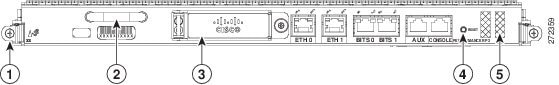
Figure 1 shows the PRP-2 connections on the Cisco XR 12000 Series Router. Figure 2 shows the PRP-3 connections on the Cisco XR 12000 Series Router.
Note ![]() Cisco IOS XR software does not support PRP-1.
Cisco IOS XR software does not support PRP-1.
Figure 1 Communication Ports on the PRP-2 for a Cisco XR 12000 Series Router

Figure 2 Communication Ports on the PRP-3
|
|
Ejector Lever |
|
|
Handle |
|
|
External Compact Flash |
|
|
Reset button |
|
|
Alphanumeric LEDs |
To connect to the router through the Console port, perform the following procedure.
SUMMARY STEPS
1. ![]() Power on the standalone router, or power on Rack 0 in a multishelf system.
Power on the standalone router, or power on Rack 0 in a multishelf system.
2. ![]() Identify the DSC.
Identify the DSC.
3. ![]() Connect a terminal to the Console port of the DSC.
Connect a terminal to the Console port of the DSC.
4. ![]() Start the terminal emulation program.
Start the terminal emulation program.
5. ![]() Press Enter.
Press Enter.
6. ![]() Log in to the router.
Log in to the router.
7. ![]() admin
admin
8. ![]() show dsc all
show dsc all
DETAILED STEPS
|
|
|
|
|---|---|---|
Step 1 |
Power on the standalone router, or power on Rack 0 in a multishelf system. |
Starts the router or Rack 0. • • |
Step 2 |
Identify the DSC. |
Identifies the RP to which you must connect in the next step. • |
Step 3 |
Connect a terminal to the Console port of the DSC. |
Establishes a communications path to the router. • • • – – – – – • |
Step 4 |
Start the terminal emulation program. |
(Optional) Prepares a computer for router communications. • • |
Step 5 |
Press Enter. |
Initiates communication with the router. • • • • • |
Step 6 |
Log in to the router. |
Establishes your access rights for the router management session. • • • |
Step 7 |
admin Example: RP/0/0/CPU0:router# admin |
Places the router in administration EXEC mode. |
Step 8 |
show dsc all Example: RP/0/0/CPU0:router(admin)# show dsc all |
Displays the DSC information for the router or router system so that you can verify that you have connected to the DSC console port. |
Where to Go Next
If you have logged into the router or multishelf system, you can perform the general router configuration as described in Configuring General Router Features.
If the router is prompting you to enter a root-system username, bring up the router. For more information, see Bringing Up the Cisco IOS XR Software on a Standalone Router.
 Feedback