Configuring Fibre Channel Routing Services and Protocols

Fabric Shortest Path First (FSPF) is the standard path selection protocol used by Fibre Channel fabrics. The FSPF feature is enabled by default on all Fibre Channel switches. Except in configurations that require special consideration, you do not need to configure any FSPF services. FSPF automatically calculates the best path between any two switches in a fabric. Specifically, FSPF is used to:

  • Dynamically compute routes throughout a fabric by establishing the shortest and quickest path between any two switches.
  • Select an alternative path in the event of the failure of a given path. FSPF supports multiple paths and automatically computes an alternative path around a failed link. It provides a preferred route when two equal paths are available.

This chapter provides details on Fibre Channel routing services and protocols. It includes the following sections:

About FSPF

FSPF is the protocol currently standardized by the T11 committee for routing in Fibre Channel networks. The FSPF protocol has the following characteristics and features:

  • Supports multipath routing.
  • Bases path status on a link state protocol.
  • Routes hop by hop, based only on the domain ID.
  • Runs only on E ports or TE ports and provides a loop free topology.
  • Runs on a per VSAN basis. Connectivity in a given VSAN in a fabric is guaranteed only for the switches configured in that VSAN.
  • Uses a topology database to keep track of the state of the links on all switches in the fabric and associates a cost with each link.
  • Guarantees a fast reconvergence time in case of a topology change. Uses the standard Dijkstra algorithm, but there is a static dynamic option for a more robust, efficient, and incremental Dijkstra algorithm. The reconvergence time is fast and efficient as the route computation is done on a per VSAN basis.

FSPF Examples

This section provides examples of topologies and applications that demonstrate the benefits of FSPF.


Note

The FSPF feature can be used on any topology.

Fault Tolerant Fabric

Fault Tolerant Fabric depicts a fault tolerant fabric using a partial mesh topology. If a link goes down anywhere in the fabric, any switch can still communicate with all others in the fabric. In the same way, if any switch goes down, the connectivity of the rest of the fabric is preserved.

Figure 1. Fault Tolerant Fabric

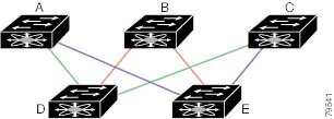
For example, if all links are of equal speed, the FSPF calculates two equal paths from A to C: A-D-C (green) and A-E-C (blue).

Redundant Links

To further improve on the topology in Fault Tolerant Fabric, each connection between any pair of switches can be replicated; two or more links can be present between a pair of switches Fault Tolerant Fabric with Redundant Links shows this arrangement. Because switches in the Cisco MDS 9000 Family support PortChanneling, each pair of physical links can appear to the FSPF protocol as one single logical link.

By bundling pairs of physical links, FSPF efficiency is considerably improved by the reduced database size and the frequency of link updates. Once physical links are aggregated, failures are not attached to a single link but to the entire PortChannel. This configuration also improves the resiliency of the network. The failure of a link in a PortChannel does not trigger a route change, thereby reducing the risks of routing loops, traffic loss, or fabric downtime for route reconfiguration.

Figure 2. Fault Tolerant Fabric with Redundant Links

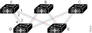
For example, if all links are of equal speed and no PortChannels exist, the FSPF calculates four equal paths from A to C: A1-E-C, A2-E-C, A3-D-C, and A4-D-C. If PortChannels exist, these paths are reduced to two.

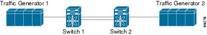
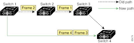
Failover Scenarios for PortChannels and FSPF Links

The SmartBits traffic generator was used to evaluate the scenarios displayed in Failover Scenario Using Traffic Generators. Two links between switch 1 and switch 2 exist as either equal-cost ISLs or PortChannels. There is one flow from traffic generator 1 to traffic generator 2. The traffic was tested at 100 percent utilization at 1 Gbps in two scenarios:

  • Disabling the traffic link by physically removing the cable (see Table 1).

  • Shutting down the links in either switch 1 or switch 2 (see Table 2).

Figure 3. Failover Scenario Using Traffic Generators
Table 1. Physically Removing the Cable for the SmartBits Scenario

PortChannel Scenario

FSPF Scenario (Equal cost ISL)

Switch 1

Switch 2

Switch 1

Switch 2

110 msec (~2K frame drops)

130+ msec (~4k frame drops)

100 msec (hold time when a signal loss is reported as mandated by the standard)
Table 2. Shutting Down the links in Switch for the SmartBits Scenario

PortChannel Scenario

FSPF Scenario (Equal cost ISL)

Switch 1

Switch 2

Switch 1

Switch 2

~0 msec (~8 frame drops)

110 msec (~2K frame drops)

130+ msec (~4K frame drops)

No hold time needed

Signal loss on switch 1

No hold time needed

Signal loss on switch 1

FSPF Global Configuration

By default, FSPF is enabled on switches in the Cisco MDS 9000 Family.

Some FSPF features can be globally configured in each VSAN. By configuring a feature for the entire VSAN, you do not have to specify the VSAN number for every command. This global configuration feature also reduces the chance of typing errors or other minor configuration errors.


Note

FSPF is enabled by default. Generally, you do not need to configure these advanced features.

Caution

The default for the backbone region is 0 (zero). You do not need to change this setting unless your region is different from the default. If you are operating with other vendors using the backbone region, you can change this default to be compatible with those settings.


This section includes the following topics:

About SPF Computational Hold Times

The SPF computational hold time sets the minimum time between two consecutive SPF computations on the VSAN. Setting this to a small value means that FSPF reacts faster to any fabric changes by recomputing paths on the VSAN. A small SPF computational hold time uses more switch CPU time.

About Link State Record Defaults

Each time a new switch enters the fabric, a link state record (LSR) is sent to the neighboring switches, and then flooded throughout the fabric. Table 1 displays the default settings for switch responses.

Table 3. LSR Default Settings

LSR Option

Default

Description

Acknowledgment interval (RxmtInterval)

5 seconds

The time a switch waits for an acknowledgment from the LSR before retransmission.

Refresh time (LSRefreshTime)

30 minutes

The time a switch waits before sending an LSR refresh transmission.

Maximum age (MaxAge)

60 minutes

The time a switch waits before dropping the LSR from the database.

The LSR minimum arrival time is the period between receiving LSR updates on this VSAN. Any LSR updates that arrive before the LSR minimum arrival time are discarded.

The LSR minimum interval time is the frequency at which this switch sends LSR updates on a VSAN.

Configuring FSPF on a VSAN

To configure an FSPF feature for the entire VSAN, follow these steps:

Procedure


Step 1

switch# config terminal

switch(config)#

Enters configuration mode.

Step 2

switch(config)# fspf config vsan 1

Enters FSPF global configuration mode for the specified VSAN.

Step 3

switch-config-(fspf-config)# spf static

Forces static SPF computation for the dynamic (default) incremental VSAN.

Step 4

switch-config-(fspf-config)# spf hold-time 10

Configures the hold time between two route computations in milliseconds (msec) for the entire VSAN. The default value is 0.

Note 
If the specified time is shorter, the routing is faster. However, the processor consumption increases accordingly.
Step 5

switch-config-(fspf-config)# region 7

Configures the autonomous region for this VSAN and specifies the region ID (7).


Resetting FSPF to the Default Configuration

To return the FSPF VSAN global configuration to its factory default, follow these steps:

Procedure


Step 1

switch# config terminal

switch(config)#

Enters configuration mode.

Step 2

switch(config)# no fspf config vsan 3

Deletes the FSPF configuration for VSAN 3.


Enabling or Disabling FSPF

To enable or disable FSPF routing protocols, follow these steps:

Procedure


Step 1

switch# config terminal

switch(config)#

Enters configuration mode.

Step 2

switch(config)# fspf enable vsan 7

Enables the FSPF routing protocol in VSAN 7.

Step 3

switch(config)# no fspf enable vsan 5

Disables the FSPF routing protocol in VSAN 5.


Clearing FSPF Counters for the VSAN

To clear the FSPF statistics counters for the entire VSAN, follow this step:

Procedure


switch# clear fspf counters vsan 1

Clears the FSPF statistics counters for the specified VSAN. If an interface reference is not specified, all counters are cleared.


FSPF Interface Configuration

Several FSPF commands are available on a per-interface basis. These configuration procedures apply to an interface in a specific VSAN.

This section includes the following topics:

About FSPF Link Cost

FSPF tracks the state of links on all switches in the fabric, associates a cost with each link in its database, and then chooses the path with a minimal cost. The cost associated with an interface can be administratively changed to implement the FSPF route selection. The integer value to specify cost can range from 1 to 30000. The default cost for 1 Gbps is 1000 and for 2 Gbps is 500.

Configuring FSPF Link Cost

To configure FSPF link cost, follow these steps:

Procedure


Step 1

switch# config t

switch(config)#

Enters configuration mode.

Step 2

switch(config)# interface fc1/4

switch(config-if)#

Configures the specified interface, or if already configured, enters configuration mode for the specified interface.

Step 3

switch(config-if)# fspf cost 5 vsan 90

Configures the cost for the selected interface in VSAN 90.


About Hello Time Intervals

You can set the FSPF Hello time interval to specify the interval between the periodic hello messages sent to verify the health of the link. The integer value can range from 1 to 65,535 seconds.


Note

This value must be the same in the ports at both ends of the ISL.

Configuring Hello Time Intervals

To configure the FSPF Hello time interval, follow these steps:

Procedure


Step 1

switch# config t

switch(config)#

Enters configuration mode.

Step 2

switch(config)# interface fc1/4

switch(config-if)#

Configures the specified interface, or if already configured, enters configuration mode for the specified interface.

Step 3

switch(config-if)# fspf hello-interval 15 vsan 175

switch(config-if)#

Specifies the hello message interval (15 seconds) to verify the health of the link in VSAN 175. The default is 20 seconds.


About Dead Time Intervals

You can set the FSPF dead time interval to specify the maximum interval for which a hello message must be received before the neighbor is considered lost and removed from the database. The integer value can range from 1 to 65,535 seconds.


Note

This value must be the same in the ports at both ends of the ISL.
  • An error is reported at the command prompt if the configured dead time interval is less than the hello time interval
  • During a software upgrade, ensure that the fspf dead-interval is greater than the ISSU downtime (80 seconds). If the fspf dead-interval is lesser than the ISSU downtime, the software upgrade fails and the following error is displayed:

Service "fspf" returned error: Dead interval for interface is less than ISSU upgrade time. 

Configuring Dead Time Intervals

To configure the FSPF dead time interval, follow these steps:

Procedure


Step 1

switch# config terminal

switch(config)#

Enters configuration mode.

Step 2

switch(config)# interface fc1/4

switch(config-if)#

Configures the specified interface, or if already configured, enters configuration mode for the specified interface.

Step 3

switch(config-if)# fspf dead-interval 25 vsan 7

switch(config-if)#

Specifies the maximum interval for VSAN 7 before which a hello message must be received on the selected interface before the neighbor is considered lost. The default is 80 seconds.


About Retransmitting Intervals

You can specify the time after which an unacknowledged link state update should be transmitted on the interface. The integer value to specify retransmit intervals can range from 1 to 65,535 seconds.


Note

This value must be the same on the switches on both ends of the interface.

Configuring Retransmitting Intervals

To configure the FSPF retransmit time interval, follow these steps:

Procedure


Step 1

switch# config terminal

switch(config)#

Enters configuration mode.

Step 2

switch(config)# interface fc1/4

switch(config-if)#

Configures the specified interface, or if already configured, enters configuration mode for the specified interface.

Step 3

switch(config-if)# fspf retransmit-interval 15 vsan 12

switch(config-if)#

Specifies the retransmit time interval for unacknowledged link state updates in VSAN 12. The default is 5 seconds.


About Disabling FSPF for Specific Interfaces

You can disable the FSPF protocol for selected interfaces. By default, FSPF is enabled on all E ports and TE ports. This default can be disabled by setting the interface as passive.


Note

FSPF must be enabled at both ends of the interface for the protocol to work.

Disabling FSPF for Specific Interfaces

You can disable the FSPF protocol for selected interfaces. By default, FSPF is enabled on all E ports and TE ports. This default can be disabled by setting the interface as passive.

To disable FSPF for a specific interface, follow these steps:

Procedure


Step 1

switch# config terminal

switch(config)#

Enters configuration mode.

Step 2

switch(config)# interface fc1/4

switch(config-if)#

Configures a specified interface, or if already configured, enters configuration mode for the specified interface.

Step 3

switch(config-if)# fspf passive vsan 1

switch(config-if)#

Disables the FSPF protocol for the specified interface in the specified VSAN.

Step 4

switch(config-if)# no fspf passive vsan 1

switch(config-if)#

Reenables the FSPF protocol for the specified interface in the specified VSAN.

You can disable the FSPF protocol for selected interfaces. By default, FSPF is enabled on all E ports and TE ports. This default can be disabled by setting the interface as passive.


Clearing FSPF Counters for an Interface

To clear the FSPF statistics counters for an interface, follow this step:

Procedure


switch# clear fspf counters vsan 200 interface fc1/1

Clears the FSPF statistics counters for the specified interface in VSAN 200.


FSPF Routes

FSPF routes traffic across the fabric, based on entries in the FSPF database. These routes can be learned dynamically, or configured statically.

This section includes the following topics:

About Fibre Channel Routes

Each port implements forwarding logic, which forwards frames based on its FC ID. Using the FC ID for the specified interface and domain, you can configure the specified route (for example FC ID 111211 and domain ID 3) in the switch with domain ID 1 (see Fibre Channel Routes).

Figure 4. Fibre Channel Routes

Note

Other than in VSANs, runtime checks are not performed on configured and suspended static routes.

About Broadcast and Multicast Routing

Broadcast and multicast in a Fibre Channel fabric uses the concept of a distribution tree to reach all switches in the fabric.

FSPF provides the topology information to compute the distribution tree. Fibre Channel defines 256 multicast groups and one broadcast address for each VSAN. Switches in the Cisco MDS 9000 Family only use broadcast routing. By default, they use the principal switch as the root node to derive a loop-free distribution tree for multicast and broadcast routing in a VSAN.


Caution

All switches in the fabric should run the same multicast and broadcast distribution tree algorithm to ensure the same distribution tree.


To interoperate with other vendor switches (following FC-SW3 guidelines), the SAN-OS and NX-OS 4.1(1b) and later software uses the lowest domain switch as the root to compute the multicast tree in interop mode.

About Multicast Root Switch

By default, the native (non-interop) mode uses the principal switch as the root. If you change the default, be sure to configure the same mode in all switches in the fabric. Otherwise, multicast traffic could encounter potential loop and frame-drop problems.


Note

The operational mode can be different from the configured interop mode. The interop mode always uses the lowest domain switch as the root.

Use the mcast root lowest vsan command to change the multicast root from the principal switch to lowest domain switch.

Setting the Multicast Root Switch

To use the lowest domain switch for the multicast tree computation, follow these steps:

Procedure


Step 1

switch# config terminal

switch(config)#

Enters configuration mode.

Step 2

switch(config)# mcast root lowest vsan 1

Uses the lowest domain switch to compute the multicast tree.

Step 3

switch(config)# mcast root principal vsan 1

Defaults to using the principal switch to compute the multicast tree.

To display the configured and operational multicast mode and the selected root domain, use the show mcast command.


switch# show mcast vsan 1
Multicast root for VSAN 1
       Configured root mode : Principal switch
       Operational root mode : Principal switch
       Root Domain ID : 0xef(239)

Load Balancing

Load balancing is a forwarding mechanism that distributes traffic over equal-cost multipath (ECMP) and port channels. Load balancing uses a hash method to identify an egress link. The hash is a function that uses parameters in the frame header to identify a unique link to forward the frame to. The load balancing scheme used depends on both the type of ingress port and egress routing. If it is intended that traffic flow in both directions on the same link, then ensure that the same load balancing scheme and hash method are used at both ends of the link.

Load Balancing Schemes

The following types of load balancing schemes are supported:

  • Flow based—All frames between a given source FCID and destination FCID are transmitted on the same link. That is, whichever link is selected for the first exchange between the source-destination pair is used for all subsequent exchanges.

  • Exchange based—The first frame in an exchange between a given source FCID and destination FCID is used to select an egress link and subsequent frames in the exchange are transmitted on the same link. However, subsequent exchanges between the source-destination pair will likely be transmitted on a different link. This provides more granular load balancing while preserving the order of frames within each exchange.

Flow Based Load Balancing illustrates how flow based load balancing works. In this example, when the first frame with a source FCID of sid1 and destination FCID of did1 is received for forwarding, port channel 2 is selected. Each subsequent frame in that flow is sent over the same port channel. No frame from sid1 to did1 utilizes port channel 1. Similarly, all frames with sid2 and did2 are sent over port channel 1. Exchange ID is not used with this type of load balancing.

Figure 5. Flow Based Load Balancing

Exchange Based Load Balancing illustrates how exchange based load balancing works. In this example, when the first frame in an exchange between a source FCID sid1 and destination FCID did1 is received for forwarding, port channel 2 is selected. All remaining frames in that particular exchange are sent on the same port channel and none are sent on port channel 1. For the next exchange, the hash algorithm chooses port channel 1. So all frames in exchange 2 between the same source-destination pair are sent on port channel 1.

Figure 6. Exchange Based Load Balancing

Hashing Methods

Load balancing is applied to an ingress frame at two levels—At the first level, an ECMP hash is used to select an egress ECMP interface (this can be either a physical interface or logical interface such as a port channel interface) and at the second level, a port channel hash is used to select an egress port channel member.

By default, the hash method that is used depends on the ingress hardware type. If either level of hash does not apply to the egress route, then no hash method is applied.

The following types of hashing methods are supported:

  • ECMP Hashing Method—If multiple paths to a destination with equal cost exist in the switch, the FIB for the ingress port is updated with these paths for that destination. This hashing method is used to select one of such paths to send frames to.

  • Port Channel Hashing Method—This hashing method is used to select an operational interface of an egress port channel.

ECMP Hashing Method illustrates how the ECMP hash method works. There are two port channels each including two equal speed links. Since the FSPF costs of the port channels are the same, both port channels are used for hashing. In this example, ECMP level hashing method selects port channel 2 as the egress port.

Figure 7. ECMP Hashing Method

Depending on the type of ingress port, the following subtypes of ECMP hashing methods are supported:

  • Type 1a

  • Type 1b

For information on which hashing method is selected for a given ingress port, see Table 1.

Port Channel Hashing Method illustrates how port channel hashing method works. Continuing the ECMP Hashing Method example where port channel 2 was selected as the egress port, a port channel hash is subsequently applied to select an egress port within the port channel. In this example, the frames are transmitted by interface 1/4 of the selected port channel.

Figure 8. Port Channel Hashing Method

Depending on the type of ingress port, the following types of port channel hashing methods are supported:

  • Type 2a

  • Type 2b

For information on which hashing method is selected for a given ingress port, see Table 1.

Table 4. Hashing Matrix

Ingress Interface

Egress Interface

ECMP Hash Method

Port Channel Hash Method

Fibre Channel or FCIP port on Cisco MDS 9500 with Generation 3 or 4 module

Fibre Channel or FCIP ISL

Type 1a

Type 2b (only when at least one FCIP port is up)

Fibre Channel port on Cisco MDS 9500 with Generation 3 or 4 module

Fibre Channel ISL

Type 1a

Type 2a

Note 

The hashing method changes to type 2b if FCIP tunnel were brought up in the switch. The hashing method will remain as type 2b even if the FCIP module is removed until the next switch reload.

Fibre Channel, FCIP, or FCoE port on Cisco MDS 9250i

Fibre Channel, FCIP, or FCoE ISL

Type 1a

Type 2b

Fibre Channel, FCIP, or FCoE port on Cisco MDS 9250i

FCIP ISL connected to Cisco MDS 24/10-Port SAN Extension Module with FCIP enhanced.

Type 1a

Type 1a

Fibre Channel port on Cisco MDS 9700

FCIP ISL

Type 1a

Type 1a

Fibre Channel or FCoE ISL

Type 1a

Type 2a

FCIP port on Cisco MDS 24/10-Port SAN Extension Module

FCIP ISL

Type 1b

Type 1b

Fibre Channel or FCoE ISL

Type 1b

Type 2a

FCoE port on Cisco MDS 9700

FCIP ISL

Type 1b

Type 1b

Fibre Channel or FCoE ISL

Type 1b

Type 2a

Fibre Channel port on Cisco MDS 9148S

Fibre Channel port on Cisco MDS 9396S

Fibre Channel port on Cisco MDS 9132T

Fibre Channel port on Cisco MDS 9396T and 9148T

Fibre Channel ISL

Type 1a

Type 2a

In-Order Delivery

In-Order Delivery (IOD) of data frames guarantees frame delivery to a destination in the same order that they were sent by the originator.

Some Fibre Channel protocols or applications cannot handle out-of-order frame delivery. In these cases, switches in the Cisco MDS 9000 Family preserve frame ordering in the frame flow. The source ID (SID), destination ID (DID), and optionally the originator exchange ID (OX ID) identify the flow of the frame.

On any given switch with IOD enabled, all frames received by a specific ingress port and destined to a certain egress port are always delivered in the same order in which they were received.

Use IOD only if your environment cannot support out-of-order frame delivery.


Tip

If you enable the in-order delivery feature, the graceful shutdown feature is not implemented.


This section includes the following topics:

About Reordering Network Frames

When you experience a route change in the network, the new selected path may be faster or less congested than the old route.

Figure 9. Route Change Delivery

In Route Change Delivery, the new path from Switch 1 to Switch 4 is faster. In this scenario, Frame 3 and Frame 4 may be delivered before Frame 1 and Frame 2.

If the in-order guarantee feature is enabled, the frames within the network are treated as follows:

  • Frames in the network are delivered in the order in which they are transmitted.

  • Frames that cannot be delivered in order within the network latency drop period are dropped inside the network.

About Reordering PortChannel Frames

When a link change occurs in a PortChannel, the frames for the same exchange flow or the same initiator-target flow can switch from one path to another faster path.

Figure 10. Link Congestion Delivery

In Link Congestion Delivery , the port of the old path (black dot) is congested. In this scenario, Frame 3 and Frame 4 can be delivered before Frame 1 and Frame 2.

The in-order delivery feature attempts to minimize the number of frames dropped during PortChannel link changes when the in-order delivery is enabled by sending a request to the remote switch on the PortChannel to flush all frames for this PortChannel.


Note

Both switches on the PortChannel must be running Cisco SAN-OS Release 3.0(1) for this IOD enhancement, known as Lossless IOD. For earlier releases, IOD waits for the switch latency period before sending new frames.

When the in-order delivery guarantee feature is enabled and a PortChannel link change occurs, the frames crossing the PortChannel are treated as follows:

  • Frames using the old path are delivered before new frames are accepted.

  • The new frames are delivered through the new path after the switch latency drop period has elapsed and all old frames are flushed.

Frames that cannot be delivered in order through the old path within the switch latency drop period are dropped. See the Configuring the Drop Latency Time.

About Enabling In-Order Delivery

You can enable the in-order delivery feature for a specific VSAN or for the entire switch. By default, in-order delivery is disabled on switches in the Cisco MDS 9000 Series.


Note

Enabling or disabling the IOD feature does not disrupt traffic.


Tip

We recommend that you only enable this feature when devices that cannot handle any out-of-order frames are connected to the fabric. Load-balancing algorithms within the Cisco MDS 9000 Series ensure that frames are delivered in order during normal fabric operation. The load-balancing algorithms based on source FC ID, destination FC ID, and exchange ID are enforced in hardware without any performance degradation. However, if the fabric encounters a failure and this feature is enabled, the recovery will be delayed because of an intentional pausing of fabric forwarding to purge the fabric of resident frames that could potentially be forwarded out-of-order.


Enabling In-Order Delivery Globally

To ensure that the in-order delivery parameters are uniform across all VSANs on an MDS switch, enable in-order delivery globally.

Only enable in-order delivery globally if this is a requirement across your entire fabric. Otherwise, enable IOD only for the VSANs that require this feature.


Note

Enable in-order delivery on the entire switch before performing a downgrade to Cisco MDS SAN-OS Release 1.3(3) or earlier.

To enable in-order delivery for the switch, follow these steps:

Procedure


Step 1

switch# config terminal

switch(config)#

Enters configuration mode.

Step 2

switch(config)# in-order-guarantee

Enables in-order delivery in the switch.

Step 3

switch(config)# no in-order-guarantee

Reverts the switch to the factory defaults and disables the in-order delivery feature.


Enabling In-Order Delivery for a VSAN

When you create a VSAN, that VSAN automatically inherits the global in-order-guarantee value. You can override this global value by enabling or disabling in-order-guarantee for the new VSAN.

To use the lowest domain switch for the multicast tree computation, follow these steps:

Procedure


Step 1

switch# config terminal

switch(config)#

Enters configuration mode.

Step 2

switch(config)# in-order-guarantee vsan 3452

Enables in-order delivery in VSAN 3452.

Step 3

switch(config)# no in-order-guarantee vsan 101

Reverts the switch to the factory defaults and disables the in-order delivery feature in VSAN 101.


Displaying the In-Order Delivery Status

Use the show in-order-guarantee command to display the present configuration status:


switch# show in-order-guarantee
global inorder delivery configuration:guaranteed
VSAN specific settings
vsan 1 inorder delivery:guaranteed
vsan 101 inorder delivery:not guaranteed
vsan 1000 inorder delivery:guaranteed
vsan 1001 inorder delivery:guaranteed
vsan 1682 inorder delivery:guaranteed
vsan 2001 inorder delivery:guaranteed
vsan 2009 inorder delivery:guaranteed
vsan 2456 inorder delivery:guaranteed
vsan 3277 inorder delivery:guaranteed
vsan 3451 inorder delivery:guaranteed
vsan 3452 inorder delivery:guaranteed

Configuring the Drop Latency Time

You can change the default latency time for a network, a specified VSAN in a network, or for the entire switch.

To configure the network and the switch drop latency time, follow these steps:

Procedure


Step 1

switch# configure terminal

switch(config)#

Enters configuration mode.

Step 2

switch(config)# fcdroplatency network 5000

Configures network drop latency time to be 5000 ms for the network. The valid range is 0 to 60000 ms. The default is 2000 ms.

Note 
The network drop latency must be computed as the sum of all switch latencies of the longest path in the network.
Step 3

switch(config)# fcdroplatency network 6000 vsan 3

Configures network drop latency time to be 6000 ms for VSAN 3.

Step 4

switch(config)# no fcdroplatency network 4500

Removes the current fcdroplatecy network configuration (4500) and reverts the switch to the factory defaults.


Displaying Latency Information

You can view the configured latency parameters using the show fcdroplatency command (see Displays Administrative Distance).

Displays Administrative Distance


switch# show fcdroplatency
 
switch latency value:500 milliseconds
global network latency value:2000 milliseconds
VSAN specific network latency settings
vsan 1 network latency:5000 milliseconds
vsan 2 network latency:2000 milliseconds
vsan 103 network latency:2000 milliseconds
vsan 460 network latency:500 milliseconds

Flow Statistics Configuration

Flow statistics count the ingress traffic in the aggregated statistics table. You can collect two kinds of statistics:

  • Aggregated flow statistics to count the traffic for a VSAN.
  • Flow statistics to count the traffic for a source and destination ID pair in a VSAN.

This section includes the following topics:

About Flow Statistics

If you enable flow counters, you can enable a maximum of 1 K entries for aggregate flow and flow statistics for Generation 1 modules, and 2 K entries for Generation 2 modules. Be sure to assign an unused flow index to a module for each new flow. Flow indexes can be repeated across modules. The number space for flow index is shared between the aggregate flow statistics and the flow statistics.

Generation 1 modules allow a maximum of 1024 flow statements per module. Generation 2 modules allow a maximum of 2048-128 flow statements per module.


Note

For each session, fcflow counter will increment only on locally connected devices and should be configured on the switch where the initiator is connected.

Counting Aggregated Flow Statistics

To count the aggregated flow statistics for a VSAN, follow these steps:

Procedure


Step 1

switch# config t

switch(config)#

Enters configuration mode.

Step 2

switch(config)# fcflow stats aggregated module 1 index 1005 vsan 1

switch(config)#

Enables the aggregated flow counter.

Step 3

switch(config)# no fcflow stats aggregated module 1 index 1005 vsan 1

switch(config)#

Disables the aggregated flow counter.


Counting Individual Flow Statistics

To count the flow statistics for a source and destination FC ID in a VSAN, follow these steps:

Procedure


Step 1

switch# config t

switch(config)#

Enters configuration mode.

Step 2

switch(config)# fcflow stats module 1 index 1 0x145601 0x5601ff 0xffffff vsan 1

switch(config)#

Enables the flow counter.

Note 
The source ID and the destination ID are specified in FC ID hex format (for example, 0x123aff). The mask can be one of 0xff0000 or 0xffffff.
Step 3

switch(config)# no fcflow stats aggregated module 2 index 1001 vsan 2

switch(config)#

Disables the flow counter.


Displaying Flow Statistics

Use the show fcflow stats commands to view flow statistics (see Example Displays Aggregated Flow Details for the Specified Module to Displays Flow Index Usage for the Specified Module).

Displays Aggregated Flow Details for the Specified Module


switch# show fcflow stats aggregated module 6
Idx  VSAN frames 			 		 bytes
---- ---- -------- 		 -------
1	 800 	 20185860	 		 1211151600

Displays Flow Details for the Specified Module


switch# show fcflow stats module 6
Idx 	 VSAN 		DID 			SID 		 Mask     		 frames 		 	 bytes
---- ----- 	------- 			 	 ------		 	 ----- 		 	-----		 ------ 
2 	 800   0x520400 		 0x530260 	 0xffffff 		 		20337793 1220267580

Displays Flow Index Usage for the Specified Module


switch# show fcflow stats usage module 6
Configured flows for module 6: 1-2

Displaying Global FSPF Information

Displays FSPF Information for a Specified VSAN displays global FSPF information for a specific VSAN:

  • Domain number of the switch.
  • Autonomous region for the switch.
  • Min_LS_arrival: minimum time that must elapse before the switch accepts LSR updates.
  • Min_LS_interval: minimum time that must elapse before the switch can transmit an LSR.

Tip

If the Min_LS_interval is higher than 10 seconds, the graceful shutdown feature is not implemented.


  • LS_refresh_time: interval time lapse between refresh LSR transmissions.
  • Max_age: maximum time aa LSR can stay before being deleted.

Displays FSPF Information for a Specified VSAN


switch# show fspf vsan 1
FSPF routing for VSAN 1
FSPF routing administration status is enabled
FSPF routing operational status is UP
It is an intra-domain router
Autonomous region is 0
SPF hold time is 0 msec
MinLsArrival = 1000 msec , MinLsInterval = 5000 msec
Local Domain is 0x65(101)
Number of LSRs = 3, Total Checksum = 0x0001288b
Protocol constants :
   LS_REFRESH_TIME = 1800 sec
   MAX_AGE         = 3600 sec
Statistics counters :
   Number of LSR that reached MaxAge = 0
   Number of SPF computations        = 7
   Number of Checksum Errors         = 0
   Number of Transmitted packets :  LSU 65 LSA 55 Hello 474 Retranmsitted LSU 0
   Number of received packets :  LSU 55 LSA 60 Hello 464 Error packets 10

Displaying the FSPF Database

Displays FSPF Database Information displays a summary of the FSPF database for a specified VSAN. If other parameters are not specified, all LSRs in the database are displayed:

  • LSR type
  • Domain ID of the LSR owner
  • Domain ID of the advertising router
  • LSR age
  • LSR incarnation member
  • Number of links

You could narrow the display to obtain specific information by issuing additional parameters for the domain ID of the LSR owner. For each interface, the following information is also available:

  • Domain ID of the neighboring switch
  • E port index
  • Port index of the neighboring switch
  • Link type and cost

Displays FSPF Database Information


switch# show fspf database vsan 1
FSPF Link State Database for VSAN 1 Domain 0x0c(12)
LSR Type                = 1
Advertising domain ID   = 0x0c(12)
LSR Age                 = 1686
LSR Incarnation number  = 0x80000024
LSR Checksum            = 0x3caf
Number of links         = 2
 NbrDomainId      IfIndex   NbrIfIndex    Link Type         Cost
-----------------------------------------------------------------------------
   0x65(101) 0x0000100e     0x00001081               1          500
   0x65(101) 0x0000100f     0x00001080               1          500
FSPF Link State Database for VSAN 1 Domain 0x65(101)
LSR Type                = 1
Advertising domain ID   = 0x65(101)
LSR Age                 = 1685
LSR Incarnation number  = 0x80000028
LSR Checksum            = 0x8443
Number of links         = 6
 NbrDomainId      IfIndex   NbrIfIndex    Link Type         Cost
-----------------------------------------------------------------------------
   0xc3(195) 0x00001085     0x00001095               1          500
   0xc3(195) 0x00001086     0x00001096               1          500
   0xc3(195) 0x00001087     0x00001097               1          500
   0xc3(195) 0x00001084     0x00001094               1          500
    0x0c(12) 0x00001081     0x0000100e               1          500
    0x0c(12) 0x00001080     0x0000100f               1          500
FSPF Link State Database for VSAN 1 Domain 0xc3(195)
LSR Type                = 1
Advertising domain ID   = 0xc3(195)
LSR Age                 = 1686
LSR Incarnation number  = 0x80000033
LSR Checksum            = 0x6799
Number of links         = 4
 NbrDomainId      IfIndex   NbrIfIndex    Link Type         Cost
-----------------------------------------------------------------------------
   0x65(101) 0x00001095     0x00001085               1          500
   0x65(101) 0x00001096     0x00001086               1          500
   0x65(101) 0x00001097     0x00001087               1          500
   0x65(101) 0x00001094     0x00001084               1          500

Displaying FSPF Interfaces

Displays FSPF Interface Information displays the following information for each selected interface.

  • Link cost
  • Timer values
  • Neighbor’s domain ID (if known)
  • Local interface number
  • Remote interface number (if known)
  • FSPF state of the interface
  • Interface counters

Displays FSPF Interface Information


switch# show fspf vsan 1 interface fc1/1
FSPF interface fc1/1 in VSAN 1
FSPF routing administrative state is active
Interface cost is 500
Timer intervals configured, Hello 20 s, Dead 80 s, Retransmit 5 s
FSPF State is FULL
Neighbor Domain Id is 0x0c(12), Neighbor Interface index is 0x0f100000
Statistics counters :
   Number of packets received : LSU  8  LSA  8  Hello 118  Error packets 0
   Number of packets transmitted : LSU  8  LSA  8  Hello 119  Retransmitted LSU 0
   Number of times inactivity timer expired for the interface = 0

Default Settings

Table 1 lists the default settings for FSPF features.

Table 5. Default FSPF Settings

Parameters

Default

FSPF

Enabled on all E ports and TE ports.

SPF computation

Dynamic.

SPF hold time

0.

Backbone region

0.

Acknowledgment interval (RxmtInterval)

5 seconds.

Refresh time (LSRefreshTime)

30 minutes.

Maximum age (MaxAge)

60 minutes.

Hello interval

20 seconds.

Dead interval

80 seconds.

Distribution tree information

Derived from the principal switch (root node).

Routing table

FSPF stores up to 16 equal cost paths to a given destination.

Load balancing

Based on destination ID and source ID on different, equal cost paths.

In-order delivery

Disabled.

Drop latency

Disabled.

Static route cost

If the cost (metric) of the route is not specified, the default is 10.

Remote destination switch

If the remote destination switch is not specified, the default is direct.

Multicast routing

Uses the principal switch to compute the multicast tree.