Configuring System-Level High Availability
This chapter describes the Cisco NX-OS high availability (HA) system and application restart operations.
This chapter includes the following sections:
•![]() Information About VSM Restarts and Switchovers
Information About VSM Restarts and Switchovers
•![]() Configuring System-Level High Availability
Configuring System-Level High Availability
Information About System-Level High Availability
This section includes the following topics:
•![]() Information About Single and Dual Supervisors
Information About Single and Dual Supervisors
•![]() Information About VSM Restarts and Switchovers
Information About VSM Restarts and Switchovers
Information About Single and Dual Supervisors
The Cisco Nexus 1000V can be configured with a single virtual supervisor module (VSM) or dual VSMs. Table 3-1 describes the HA supervisor roles for single and dual VSM operation.
This section includes the following topics:
•![]() Dual Supervisor Active and Standby Redundancy States
Dual Supervisor Active and Standby Redundancy States
•![]() Dual Supervisor Synchronization
Dual Supervisor Synchronization
HA Supervisor Roles
The redundancy role indicates not only whether the VSM interacts with other VSMs, but also the module number it occupies. Table 3-2 shows the available HA roles for VSMs.
Dual Supervisor Active and Standby Redundancy States
Independent of its role, the redundancy state of a VSM can be one of those described in Table 3-3.
Dual Supervisor Synchronization
The active and standby VSMs are in the operationally HA state and can automatically synchronize when the internal state of one supervisor module is Active with HA Standby and the internal state of the other supervisor module is HA Standby.
If the output of the show system redundancy command indicates that the operational redundancy mode of the active VSM is None, then the active and standby VSMs are not yet synchronized. The following example shows the VSM internal state of dual supervisors as observed in the output of the show system redundancy status command.
switch# show system redundancy status
Redundancy role
---------------
administrative: standalone
operational: standalone
Redundancy mode
---------------
administrative: HA
operational: None
This supervisor (sup-1)
-----------------------
Redundancy state: Active
Supervisor state: Active
Internal state: Active with no standby
Other supervisor (sup-2)
------------------------
Redundancy state: Not present
switch#
Information About VSM Restarts and Switchovers
This section includes the following topics:
Restarts on Standalone VSMs
In a system with only one supervisor, when all HA policies have been unsuccessful in restarting a service, the supervisor restarts. The supervisor and all services restart with no prior state information.
Restarts on Dual VSMs
When a VSM fails in a system with dual supervisors, the system performs a switchover rather than a system restart in order to maintain a stateful operation. In some cases, however, a switchover may not be possible at the time of the failure. For example, if the standby VSM is not in a stable standby state, a restart rather than a switchover is performed.
Switchovers on Dual VSMs
A dual VSM configuration allows uninterrupted traffic forwarding with stateful switchover (SSO) when a failure occurs in the VSM. The two VSMs operate in an active/standby capacity in which only one is active at any given time, while the other acts as a standby backup. The two VSMs constantly synchronize the state and configuration in order to provide a seamless and stateful switchover of most services if the active VSM fails.
This section includes the following topics:
Switchover Characteristics
A switchover occurs when the active supervisor fails (for example, if repeated failures occur in an essential service or if the system hosting the VSM fails).
A user-triggered switchover could occur (for example, if you need to perform maintenance tasks on the system hosting the active VSM).
An HA switchover has the following characteristics:
•![]() It is stateful (nondisruptive) because control traffic is not affected.
It is stateful (nondisruptive) because control traffic is not affected.
•![]() It does not disrupt data traffic because the VEMs are not affected.
It does not disrupt data traffic because the VEMs are not affected.
Automatic Switchovers
When a stable standby VSM detects that the active VSM has failed, it initiates a switchover and transitions to active. When a switchover begins, another switchover cannot be started until a stable standby VSM is available.
If a standby VSM that is not stable detects that the active VSM has failed, then, instead of initiating a switchover, it tries to restart the system.
Manual Switchovers
Before you can initiate a manual switchover from the active to the standby VSM, the standby VSM must be stable. To find out if it is, see the "Verifying that a System is Ready for a Switchover" section.
Once you have verified that the standby VSM is stable, you can manually initiate a switchover (see the "Manually Switching the Active VSM to Standby" section).
Once a switchover process begins, another switchover process cannot be started until a stable standby VSM is available.
Guidelines and Limitations
Follow these guidelines and limitations when configuring system-level high availability:
•![]() Although primary and secondary VSMs can reside in the same host, to improve redundancy, install them in separate hosts and, if possible, connected to different upstream switches.
Although primary and secondary VSMs can reside in the same host, to improve redundancy, install them in separate hosts and, if possible, connected to different upstream switches.
•![]() The console for the standby VSM is available through the vSphere client or using the command, module attach <x>, but configuration is not allowed and many commands are restricted. The module attach <x> command would be run at the console of the active VSM.
The console for the standby VSM is available through the vSphere client or using the command, module attach <x>, but configuration is not allowed and many commands are restricted. The module attach <x> command would be run at the console of the active VSM.
•![]() You cannot use Telnet or Secure Shell (SSH) protocols to communicate with the standby VSM because the management interface IP is unconfigured until the VSM becomes active.
You cannot use Telnet or Secure Shell (SSH) protocols to communicate with the standby VSM because the management interface IP is unconfigured until the VSM becomes active.
Configuring System-Level High Availability
This section includes the following topics:
•![]() Adding a Second VSM to a Standalone System
Adding a Second VSM to a Standalone System
•![]() Replacing the Standby in a Dual VSM System
Replacing the Standby in a Dual VSM System
•![]() Replacing the Active in a Dual VSM System
Replacing the Active in a Dual VSM System
•![]() Changing the Domain ID in a Dual VSM System
Changing the Domain ID in a Dual VSM System
Changing the VSM Role
Use this procedure to change the role of a VSM to one of the following after it is already in service:
•![]() Standalone
Standalone
•![]() Primary
Primary
•![]() Secondary
Secondary
BEFORE YOU BEGIN
Before beginning this procedure, you must know or do the following:

•![]() If you are changing a standalone VSM to a secondary VSM, be sure to first isolate it from the other VSM in the pair to prevent any interaction with the primary VSM during the change. Power the VM off from the vSphere Client before reconnecting it as standby.
If you are changing a standalone VSM to a secondary VSM, be sure to first isolate it from the other VSM in the pair to prevent any interaction with the primary VSM during the change. Power the VM off from the vSphere Client before reconnecting it as standby.
For an example of changing the port groups and port profiles assigned to the VSM interfaces in the vSphere Client, see the following document:
–![]() Cisco Nexus 1000V Software Installation Guide, Release 4.0(4)SV1(2)
Cisco Nexus 1000V Software Installation Guide, Release 4.0(4)SV1(2)
To change a standalone VSM to a secondary VSM, see the "Adding a Second VSM to a Standalone System" section.
•![]() You are logged into the CLI in EXEC mode.
You are logged into the CLI in EXEC mode.

Note ![]() The Cisco Nexus 1000V VSM software installation provides an opportunity for you to designate the role for each VSM. You can use this procedure to change that initial configuration.
The Cisco Nexus 1000V VSM software installation provides an opportunity for you to designate the role for each VSM. You can use this procedure to change that initial configuration.
•![]() The possible HA roles are standalone, primary, and secondary.
The possible HA roles are standalone, primary, and secondary.
For more information, see the "HA Supervisor Roles" section.
•![]() The possible HA redundancy states are active and standby.
The possible HA redundancy states are active and standby.
For more information, see the "Dual Supervisor Active and Standby Redundancy States" section.
•![]() To activate a change from primary to secondary VSM, you must reload the VSM by doing one of the following:
To activate a change from primary to secondary VSM, you must reload the VSM by doing one of the following:
–![]() Issue the reload command.
Issue the reload command.
–![]() Power the VM off and then on from the vSphere Client.
Power the VM off and then on from the vSphere Client.
•![]() A change from a standalone to a primary VSM takes effect immediately.
A change from a standalone to a primary VSM takes effect immediately.
SUMMARY STEPS
1. ![]() system redundancy role {standalone | primary | secondary}
system redundancy role {standalone | primary | secondary}
2. ![]() show system redundancy status
show system redundancy status
3. ![]() copy running-config startup-config
copy running-config startup-config
DETAILED STEPS
EXAMPLE
This example shows how to display the system redundancy status of a standalone VSM:
switch# show system redundancy status
Redundancy role
---------------
administrative: standalone
operational: standalone
Redundancy mode
---------------
administrative: HA
operational: None
This supervisor (sup-1)
-----------------------
Redundancy state: Active
Supervisor state: Active
Internal state:Active with no standby
Other supervisor (sup-2)
------------------------
Redundancy state: Not present
switch#
Configuring a Switchover
This section includes the following procedures for configuring a switchover in a dual VSM system:
•![]() Verifying that a System is Ready for a Switchover
Verifying that a System is Ready for a Switchover
•![]() Manually Switching the Active VSM to Standby
Manually Switching the Active VSM to Standby
Guidelines and Limitations
Follow these guidelines when performing a switchover:
•![]() When you manually initiate a switchover, system messages are generated that indicate the presence of two VSMs and identify which one is becoming active.
When you manually initiate a switchover, system messages are generated that indicate the presence of two VSMs and identify which one is becoming active.
•![]() A switchover can only be performed when both VSMs are functioning.
A switchover can only be performed when both VSMs are functioning.
Verifying that a System is Ready for a Switchover
Use this procedure to verify that both an active and standby VSM are in place and operational before proceeding with a switchover.
BEFORE YOU BEGIN
Before beginning this procedure, you must know or do the following:
•![]() You are logged into the CLI in EXEC mode.
You are logged into the CLI in EXEC mode.
•![]() If the standby VSM is not in a stable state (the state must be ha-standby), then a manually initiated switchover cannot be performed.
If the standby VSM is not in a stable state (the state must be ha-standby), then a manually initiated switchover cannot be performed.
SUMMARY STEPS
1. ![]() show system redundancy status
show system redundancy status
2. ![]() show module
show module
DETAILED STEPS
EXAMPLE
This example shows how to display information about all available VEMs and VSMs in the system:
n1000v# show module
Mod Ports Module-Type Model Status
--- ----- -------------------------------- ------------------ ------------
1 0 Virtual Supervisor Module Nexus1000V active *
2 0 Virtual Supervisor Module Nexus1000V ha-standby
3 248 Virtual Ethernet Module NA ok
Mod Sw Hw
--- --------------- ------
1 4.0(4)SV1(0.37) 0.0
2 4.0(4)SV1(0.37) 0.0
3 4.0(4)SV1(0.37) 0.4
Mod MAC-Address(es) Serial-Num
--- -------------------------------------- ----------
1 00-19-07-6c-5a-a8 to 00-19-07-6c-62-a8 NA
2 00-19-07-6c-5a-a8 to 00-19-07-6c-62-a8 NA
3 02-00-0c-00-21-00 to 02-00-0c-00-21-80 NA
Mod Server-IP Server-UUID Server-Name
--- --------------- ------------------------------------ --------------------
1 192.168.48.66 NA NA
2 192.168.48.66 NA NA
3 192.168.48.45 b497bc96-1583-32f1-9062-de3b5d37709c strider.cisco.com
* this terminal session
Manually Switching the Active VSM to Standby
Use this procedure to manually switch an active VSM to standby in a dual supervisor system.
BEFORE YOU BEGIN
Before beginning this procedure, you must know or do the following:
•![]() You are logged in to the active VSM CLI in EXEC mode.
You are logged in to the active VSM CLI in EXEC mode.
•![]() You have completed the steps in the "Verifying that a System is Ready for a Switchover" section, and have found the system to be ready for a switchover.
You have completed the steps in the "Verifying that a System is Ready for a Switchover" section, and have found the system to be ready for a switchover.
•![]() A switchover can only be performed when two VSMs are functioning in the switch.
A switchover can only be performed when two VSMs are functioning in the switch.
•![]() If the standby VSM is not in a stable state (ha-standby), then you cannot initiate a manual switchover. You will see the following error message:
If the standby VSM is not in a stable state (ha-standby), then you cannot initiate a manual switchover. You will see the following error message:
Failed to switchover (standby not ready to takeover in vdc 1)
•![]() Once you enter the system switchover command, you cannot start another switchover process on the same system until a stable standby VSM is available.
Once you enter the system switchover command, you cannot start another switchover process on the same system until a stable standby VSM is available.
•![]() If a switchover does not complete successfully within 28 seconds, the supervisors will reset.
If a switchover does not complete successfully within 28 seconds, the supervisors will reset.
•![]() Any unsaved running configuration that was available at active VSM is still unsaved in the new active VSM. You can verify this unsaved running configuration using the show running-config diff command. Save that configuration, if needed, as you would do in the other VSM (by entering the copy running-config startup-config command).
Any unsaved running configuration that was available at active VSM is still unsaved in the new active VSM. You can verify this unsaved running configuration using the show running-config diff command. Save that configuration, if needed, as you would do in the other VSM (by entering the copy running-config startup-config command).
SUMMARY STEPS
1. ![]() system switchover
system switchover
2. ![]() show running-config diff
show running-config diff
3. ![]() copy running-config startup-config
copy running-config startup-config
DETAILED STEPS
EXAMPLES
This example shows how to switch an active VSM to the standby VSM and displays the output that appears on the standby VSM as it becomes the active VSM.
n1000v# system switchover
----------------------------
2009 Mar 31 04:21:56 n1000v %$ VDC-1 %$ %SYSMGR-2-HASWITCHOVER_PRE_START: This supervisor is becoming active (pre-start phase). 2009 Mar 31 04:21:56 n1000v %$ VDC-1 %$ %SYSMGR-2-HASWITCHOVER_START: This supervisor is becoming active. 2009 Mar 31 04:21:57 n1000v %$ VDC-1 %$ %SYSMGR-2-SWITCHOVER_OVER: Switchover completed. 2009 Mar 31 04:22:03 n1000v %$ VDC-1 %$ %PLATFORM-2-MOD_REMOVE: Module 1 removed (Serial number )
This example shows how to display the difference between the running and startup configurations:
n1000v# show running-config diff
*** Startup-config
--- Running-config
***************
*** 1,38 ****
version 4.0(4)SV1(1)
role feature-group name new
role name testrole
username admin password 5 $1$S7HvKc5G$aguYqHl0dPttBJAhEPwsy1 role network-admin
telnet server enable
ip domain-lookup
Adding a Second VSM to a Standalone System
Use this section to change a standalone system into a dual supervisor system by adding a second VSM.
This section includes the following topics:
•![]() Adding a Second VSM to a Standalone System
Adding a Second VSM to a Standalone System
•![]() Changing the Standalone VSM to a Primary VSM
Changing the Standalone VSM to a Primary VSM
•![]() Verifying the Change to a Dual VSM System
Verifying the Change to a Dual VSM System
BEFORE YOU BEGIN
Before adding a second VSM to a standalone system, you must know or do the following:
•![]() You are logged into the CLI in EXEC mode.
You are logged into the CLI in EXEC mode.
•![]() You have the Cisco Nexus 1000V Software Installation Guide, Release 4.0(4)SV1(2) document available.
You have the Cisco Nexus 1000V Software Installation Guide, Release 4.0(4)SV1(2) document available.
•![]() Although primary and secondary VSMs can reside in the same host, to improve redundancy, install them in separate hosts and, if possible, connected to different upstream switches.
Although primary and secondary VSMs can reside in the same host, to improve redundancy, install them in separate hosts and, if possible, connected to different upstream switches.
•![]() When installing the second VSM, assign it with the secondary role.
When installing the second VSM, assign it with the secondary role.
•![]() Set up the port groups for the dual VSM VMs with the same parameters in both hosts.
Set up the port groups for the dual VSM VMs with the same parameters in both hosts.
•![]() After the secondary VSM is installed, the following occurs automatically:
After the secondary VSM is installed, the following occurs automatically:
–![]() The secondary VSM is reloaded and added to the system.
The secondary VSM is reloaded and added to the system.
–![]() The secondary VSM negotiates with the primary VSM and becomes the standby VSM.
The secondary VSM negotiates with the primary VSM and becomes the standby VSM.
–![]() The standby VSM synchronizes the configuration and state with the primary VSM.
The standby VSM synchronizes the configuration and state with the primary VSM.
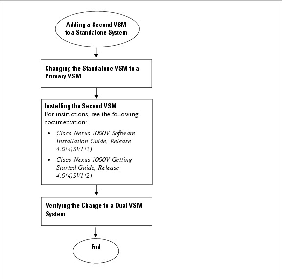
Flow Chart: Adding a Second VSM to a Standalone System
The following flow chart (see Figure 3-1) is designed to guide you through the process of adding a second VSM to a standalone system. After completing each procedure, return to the flow chart to make sure that you complete all required procedures in the correct sequence.
Figure 3-1 Adding a Second VSM to a Standalone System
Changing the Standalone VSM to a Primary VSM
Use this procedure to change the role of a VSM from standalone in a single VSM system to primary in a dual VSM system.
BEFORE YOU BEGIN
Before beginning this procedure, you must know or do the following:
•![]() You are logged into the CLI in EXEC mode.
You are logged into the CLI in EXEC mode.
•![]() A change from a standalone to a primary VSM takes effect immediately.
A change from a standalone to a primary VSM takes effect immediately.
SUMMARY STEPS
1. ![]() system redundancy role primary
system redundancy role primary
2. ![]() show system redundancy status
show system redundancy status
3. ![]() copy running-config startup-config
copy running-config startup-config
DETAILED STEPS
EXAMPLE
This example shows how to display the current system redundancy status for the VSM:
n1000v# show system redundancy status
Redundancy role
---------------
administrative: primary
operational: primary
Redundancy mode
---------------
administrative: HA
operational: None
This supervisor (sup-1)
-----------------------
Redundancy state: Active
Supervisor state: Active
Internal state: Active with no standby
Other supervisor (sup-2)
------------------------
Redundancy state: Not present
Verifying the Change to a Dual VSM System
Use this procedure to verify a change from a single VSM to a dual VSM system.
BEFORE YOU BEGIN
Before beginning this procedure, you must know or do the following:
•![]() You are logged into the CLI in EXEC mode.
You are logged into the CLI in EXEC mode.
•![]() You have already changed the single VSM role from standalone to primary (see the "Changing the Standalone VSM to a Primary VSM" section).
You have already changed the single VSM role from standalone to primary (see the "Changing the Standalone VSM to a Primary VSM" section).
•![]() You have already installed the second VSM using the Cisco Nexus 1000V Software Installation Guide, Release 4.0(4)SV1(2).
You have already installed the second VSM using the Cisco Nexus 1000V Software Installation Guide, Release 4.0(4)SV1(2).
SUMMARY STEPS
1. ![]() show system redundancy status
show system redundancy status
2. ![]() show module
show module
DETAILED STEPS
EXAMPLES
This example shows how to display the current redundancy status for VSMs in the system. In this example, the primary and secondary VSMs are shown following a change from a single VSM system to a dual VSM system.
n1000v# show system redundancy status
Redundancy role --------------- administrative: primary operational: primary
Redundancy mode --------------- administrative: HA operational: HA
This supervisor (sup-1)
-----------------------
Redundancy state: Active
Supervisor state: Active
Internal state: Active with HA standby
Other supervisor (sup-2)
------------------------
Redundancy state: Standby
Supervisor state: HA standby
Internal state: HA standby
This example shows how to display information about all available VSMs and VEMs in the system. In this example, the primary and secondary VSMs are shown following a change from a single VSM system to a dual VSM system. In addition, there is one VEM in module 3.
n1000v# show module
Mod Ports Module-Type Model Status
--- ----- -------------------------------- ------------------ ------------
1 0 Virtual Supervisor Module Nexus1000V active *
2 0 Virtual Supervisor Module Nexus1000V ha-standby
3 248 Virtual Ethernet Module NA ok
Mod Sw Hw
--- --------------- ------
1 4.0(4)SV1(0.37) 0.0
2 4.0(4)SV1(0.37) 0.0
3 4.0(4)SV1(0.37) 0.4
Mod MAC-Address(es) Serial-Num
--- -------------------------------------- ----------
1 00-19-07-6c-5a-a8 to 00-19-07-6c-62-a8 NA
2 00-19-07-6c-5a-a8 to 00-19-07-6c-62-a8 NA
3 02-00-0c-00-21-00 to 02-00-0c-00-21-80 NA
Mod Server-IP Server-UUID Server-Name
--- --------------- ------------------------------------ --------------------
1 192.168.48.66 NA NA
2 192.168.48.66 NA NA
3 192.168.48.45 b497bc96-1583-32f1-9062-de3b5d37709c strider.cisco.com
* this terminal session
Replacing the Standby in a Dual VSM System
Use this procedure to replace a standby/secondary VSM in a dual VSM system.
Note ![]() Equipment Outage—This procedures requires that you power down and reinstall a VSM. During this time, your system will be operating with a single VSM.
Equipment Outage—This procedures requires that you power down and reinstall a VSM. During this time, your system will be operating with a single VSM.
Step 1 ![]() Power off the standby VSM.
Power off the standby VSM.
Step 2 ![]() Install the new VSM as a standby, with the same domain ID as the existing VSM, using the procedure in the "Installing and Configuring the VSM VM" section in the Cisco Nexus 1000V Software Installation Guide, Release 4.0(4)SV1(2).
Install the new VSM as a standby, with the same domain ID as the existing VSM, using the procedure in the "Installing and Configuring the VSM VM" section in the Cisco Nexus 1000V Software Installation Guide, Release 4.0(4)SV1(2).
Once the new VSM is added to the system, it will synchronize with the existing VSM.
Replacing the Active in a Dual VSM System
Use this procedure to replace an active/primary VSM in a dual VSM system.
BEFORE YOU BEGIN
Before beginning this procedure, you must know or do the following:
•![]() You are logged into the CLI in EXEC mode.
You are logged into the CLI in EXEC mode.
•![]() You must configure the port groups so that the new primary VSM cannot communicate with the secondary VSM or any of the VEMs during setup. VSMs with a primary or secondary redundancy role have built-in mechanisms for detecting and resolving the conflict between two VSMs in the active state. In order to avoid these mechanisms during the configuration of the new primary VSM, you must isolate the new primary VSM from the secondary VSM.
You must configure the port groups so that the new primary VSM cannot communicate with the secondary VSM or any of the VEMs during setup. VSMs with a primary or secondary redundancy role have built-in mechanisms for detecting and resolving the conflict between two VSMs in the active state. In order to avoid these mechanisms during the configuration of the new primary VSM, you must isolate the new primary VSM from the secondary VSM.
Note ![]() Equipment Outage—This procedures requires powering down and reinstalling a VSM. During this time, your system will be operating with a single VSM.
Equipment Outage—This procedures requires powering down and reinstalling a VSM. During this time, your system will be operating with a single VSM.
Step 1 ![]() Power off the active VSM.
Power off the active VSM.
The secondary VSM becomes active.
Step 2 ![]() On the vSphere Client, change the port group configuration for the new primary VSM to prevent communication with the secondary VSM and the VEMs during setup.
On the vSphere Client, change the port group configuration for the new primary VSM to prevent communication with the secondary VSM and the VEMs during setup.
For an example of changing the port groups and port profiles assigned to the VSM interfaces in the vSphere Client, see the Cisco Nexus 1000V Software Installation Guide, Release 4.0(4)SV1(2)
Step 3 ![]() Install the new VSM as a primary, with the same domain ID as the existing VSM, using "Installing and Configuring the VSM VM" section in the Cisco Nexus 1000V Software Installation Guide, Release 4.0(4)SV1(2).
Install the new VSM as a primary, with the same domain ID as the existing VSM, using "Installing and Configuring the VSM VM" section in the Cisco Nexus 1000V Software Installation Guide, Release 4.0(4)SV1(2).
Step 4 ![]() Save the configuration.
Save the configuration.
Step 5 ![]() Power off the VM.
Power off the VM.
Step 6 ![]() On the vSphere Client, change the port group configuration for the new primary VSM to permit communication with the secondary VSM and the VEMs.
On the vSphere Client, change the port group configuration for the new primary VSM to permit communication with the secondary VSM and the VEMs.
Step 7 ![]() Power up the new primary VSM.
Power up the new primary VSM.
The new primary VSM starts and automatically synchronizes all configuration data with the secondary, which is currently the active VSM. Because the existing VSM is active, the new primary VSM becomes the standby VSM and receives all configuration data from the existing active VSM.
Changing the Domain ID in a Dual VSM System
Use this procedure to change the domain ID in a dual VSM system.
BEFORE YOU BEGIN
Before beginning this procedure, you must know or do the following:
•![]() You have access to the console of both the active and standby VSM.
You have access to the console of both the active and standby VSM.
•![]() VSMs with a primary or secondary redundancy role have built-in mechanisms for detecting and resolving the conflict between two VSMs in the active state. In order to avoid these mechanisms while changing the domain ID, you must isolate the standby VSM from the active VSM. This procedure has a step for isolating the VSMs.
VSMs with a primary or secondary redundancy role have built-in mechanisms for detecting and resolving the conflict between two VSMs in the active state. In order to avoid these mechanisms while changing the domain ID, you must isolate the standby VSM from the active VSM. This procedure has a step for isolating the VSMs.
Note ![]() Equipment Outage—This procedures requires powering down a VSM. During this time, your system will be operating with a single VSM.
Equipment Outage—This procedures requires powering down a VSM. During this time, your system will be operating with a single VSM.
DETAILED STEPS
Step 1 ![]() On the vSphere Client for the standby VSM, do one of the following to isolate the VSMs and prevent their communication while completing this procedure:
On the vSphere Client for the standby VSM, do one of the following to isolate the VSMs and prevent their communication while completing this procedure:
•![]() Change the port group configuration for the interfaces using port groups that prevent the VSMs from communicating with each other.
Change the port group configuration for the interfaces using port groups that prevent the VSMs from communicating with each other.
•![]() Unmark the "Connected" option for the interfaces.
Unmark the "Connected" option for the interfaces.
The standby VSM becomes active but cannot communicate with the other active VSM or the VEM.
Step 2 ![]() At the console of the standby VSM, change the domain id and save the configuration.
At the console of the standby VSM, change the domain id and save the configuration.
Example:
n1000v# config t
n1000v(config)# svs-domain
n1000v(config-svs-domain)# domain id 100
n1000v(config-svs-domain)# copy running-config startup-config
The domain id is changed on the standby VSM and the VEM connected to it.
Step 3 ![]() Power down the standby VSM.
Power down the standby VSM.
Step 4 ![]() At the console of the active VSM, change the domain id and save the configuration.
At the console of the active VSM, change the domain id and save the configuration.
Example:
n1000v# config t
n1000v(config)# svs-domain
n1000v(config-svs-domain)# domain id 100
n1000v(config-svs-domain)# copy running-config startup-config
The domain id is changed on the active VSM and the VEM connected to it.
Step 5 ![]() On the vSphere Client for the standby VSM, do one of the following to permit communication with the active VSM:
On the vSphere Client for the standby VSM, do one of the following to permit communication with the active VSM:
•![]() Change the port group configuration for the interfaces.
Change the port group configuration for the interfaces.
•![]() Make sure the "Connect at power on" option is marked for the interfaces.
Make sure the "Connect at power on" option is marked for the interfaces.
Once powered up, the standby VSM will be able to communicate with the active VSM.
Step 6 ![]() Power up the standby VSM.
Power up the standby VSM.
Both VSMs are now using the new domain ID and will synchronize.
Verifying the HA Status
Use this procedure to display and verify the HA status of the system.
SUMMARY STEPS
1. ![]() show system redundancy status
show system redundancy status
2. ![]() show module
show module
3. ![]() show processes
show processes
DETAILED STEPS
EXAMPLES
This example shows how to display the system redundancy status:
n1000v# show system redundancy status
Redundancy role
---------------
administrative: primary
operational: primary
Redundancy mode
---------------
administrative: HA
operational: HA
This supervisor (sup-1)
-----------------------
Redundancy state: Active
Supervisor state: Active
Internal state: Active with HA standby
Other supervisor (sup-2)
------------------------
Redundancy state: Standby
Supervisor state: HA standby
Internal state: HA standby
This example shows how to display information about all available VSMs and VEMs in the system:
n1000v# show module
Mod Ports Module-Type Model Status
--- ----- -------------------------------- ------------------ ------------
1 0 Virtual Supervisor Module Nexus1000V active *
2 0 Virtual Supervisor Module Nexus1000V ha-standby
3 248 Virtual Ethernet Module NA ok
Mod Sw Hw
--- --------------- ------
1 4.0(4)SV1(0.37) 0.0
2 4.0(4)SV1(0.37) 0.0
3 4.0(4)SV1(0.37) 0.4
Mod MAC-Address(es) Serial-Num
--- -------------------------------------- ----------
1 00-19-07-6c-5a-a8 to 00-19-07-6c-62-a8 NA
2 00-19-07-6c-5a-a8 to 00-19-07-6c-62-a8 NA
3 02-00-0c-00-21-00 to 02-00-0c-00-21-80 NA
Mod Server-IP Server-UUID Server-Name
--- --------------- ------------------------------------ --------------------
1 192.168.48.66 NA NA
2 192.168.48.66 NA NA
3 192.168.48.45 b497bc96-1583-32f1-9062-de3b5d37709c strider.cisco.com
* this terminal session
This example shows how to display the state of all processes and the start count of the process:
n1000v# show processes
PID State PC Start_cnt TTY Type Process
----- ----- -------- ----------- ---- ---- -------------
1 S 77f8a468 1 - O init
2 S 0 1 - O ksoftirqd/0
3 S 0 1 - O desched/0
4 S 0 1 - O events/0
5 S 0 1 - O khelper
10 S 0 1 - O kthread
18 S 0 1 - O kblockd/0
35 S 0 1 - O khubd
119 S 0 1 - O pdflush
120 S 0 1 - O pdflush
122 S 0 1 - O aio/0
121 S 0 1 - O kswapd0
707 S 0 1 - O kseriod
754 S 0 1 - O kide/0
762 S 0 1 - O scsi_eh_0
1083 S 0 1 - O kjournald
1088 S 0 1 - O kjournald
1603 S 0 1 - O kjournald
1610 S 0 1 - O kjournald
1920 S 77f6c18e 1 - O portmap
1933 S 0 1 - O nfsd
1934 S 0 1 - O nfsd
1935 S 0 1 - O nfsd
1936 S 0 1 - O nfsd
1937 S 0 1 - O nfsd
1938 S 0 1 - O nfsd
1939 S 0 1 - O nfsd
1940 S 0 1 - O nfsd
1941 S 0 1 - O lockd
1942 S 0 1 - O rpciod
1947 S 77f6e468 1 - O rpc.mountd
1957 S 77f6e468 1 - O rpc.statd
1984 S 77dfe468 1 - VG sysmgr
2265 S 0 1 - O mping-thread
2266 S 0 1 - O mping-thread
2280 S 0 1 - O redun_kthread
2281 S 0 1 - O redun_timer_kth
2341 S 0 1 - O stun_kthread
2817 S 0 1 - O sf_rdn_kthread
2818 S 77f37468 1 - VU xinetd
2819 S 77f6e468 1 - VU tftpd
2820 S 7784f1b6 1 - VL syslogd
2821 S 77ec2468 1 - VU sdwrapd
2822 S 77dbf468 1 - VU platform
2830 S 0 1 - O ls-notify-mts-t
2842 S 77ea5be4 1 - VU pfm_dummy
3270 S 77f836be 1 - O klogd
3274 S 77d84be4 1 - VL vshd
3275 S 77a41f43 1 - VL smm
3276 S 77e41468 1 - VL session-mgr
3277 S 77c26468 1 - VL psshelper
3278 S 77f75468 1 - VU lmgrd
3279 S 77e5cbe4 1 - VG licmgr
3280 S 77eb2468 1 - VG fs-daemon
3281 S 77eb8468 1 - VL feature-mgr
3282 S 77e72468 1 - VU confcheck
3283 S 77e9e468 1 - VU capability
3284 S 77c26468 1 - VU psshelper_gsvc
3294 S 77f75468 1 - O cisco
3311 S 77856f43 1 - VL clis
3360 S 77cbd468 1 - VL xmlma
3361 S 77e5b468 1 - VL vmm
3362 S 77b44468 1 - VG vdc_mgr
3363 S 77e71468 1 - VU ttyd
3364 R 77e9e5f5 1 - VL sysinfo
3365 S 77b5a468 1 - VL sksd
3366 S 77e9b468 1 - VG res_mgr
3367 S 77e44468 1 - VG plugin
3368 S 77ccc468 1 - VL mvsh
3369 S 77dfc468 1 - VU module
3370 S 77ccb468 1 - VL evms
3371 S 77ccc468 1 - VL evmc
3373 S 77ec1468 1 - VU core-dmon
3374 S 7761c40d 1 - VL ascii-cfg
3375 S 77cd9be4 1 - VL securityd
3376 S 77ca3468 1 - VU cert_enroll
3377 S 77b11be4 1 - VL aaa
3380 S 77a38f43 1 - VL l3vm
3381 S 77a2ef43 1 - VL u6rib
3383 S 77a2ef43 1 - VL urib
3384 S 77e13468 1 - VU ExceptionLog
3385 S 77df0468 1 - VU bootvar
3386 S 77dbc468 1 - VG ifmgr
3387 S 77ea0468 1 - VU tcap
3390 S 77f2abe4 1 - VU core-client
3418 S 77a3ff43 1 - VL adjmgr
3431 S 77f836be 1 1 O getty
3432 S 77a7deee 1 S0 O vsh
3434 S 77f1deee 1 - O gettylogin1
3454 S 77a41f43 1 - VL arp
3455 S 7786d896 1 - VL icmpv6
3456 S 778e1f43 1 - VL netstack
3510 S 776c340d 1 - VL radius
3511 S 77f58be4 1 - VL ip_dummy
3512 S 77f58be4 1 - VL ipv6_dummy
3513 S 7780640d 1 - VU ntp
3514 S 77f58be4 1 - VL pktmgr_dummy
3515 S 7786540d 1 - VL snmpd
3517 S 777f540d 1 - VL cdp
3706 S 77f836be 1 S1 O getty
3711 S 77b66468 1 - VL aclmgr
3718 S 77d18468 1 - VU aclcomp
3871 S 778b440d 1 - VL ufdm
3872 S 77d08468 1 - VU sf_nf_srv
3873 S 779dff43 1 - VL rpm
3874 S 7789340d 1 - VG pltfm_config
3875 S 77ef4468 1 - VU pixmc
3876 S 77dd5468 1 - VG pixm
3877 S 7786640d 1 - VL nfm
3878 S 77dc9468 1 - VU msp
3879 S 77d82468 1 - VL monitor
3880 S 7786240d 1 - VL mfdm
3881 S 7784140d 1 - VL l2fm
3882 S 77d90468 1 - VL ipqosmgr
3883 S 77bf8468 1 - VU copp
3885 S 75f39497 1 - VU vms
3891 S 779ca27b 1 - VL igmp
3929 S 77b3d468 1 - VL eth_port_channel
3930 S 77cd5468 1 - VL vlan_mgr
3934 S 7777e40d 1 - VL ethpm
3960 S 77b58468 1 - VL eth-port-sec
3961 S 77a93468 1 - VL stp
3998 S 77d7f468 1 - VL private-vlan
3999 S 77d4e468 1 - VU vim
4009 S 77da9468 1 - VL lacp
4016 S 77d5d468 1 - VU portprofile
4221 S 77f58be4 1 - VL tcpudp_dummy
4226 S 77c12468 1 - VU pdl_srv_tst
4242 S 77e55468 1 - VU ethanalyzer
4243 S 77afb40d 1 - VL dcos-thttpd
4244 S 77ad740d 1 - VL dcos-xinetd
4261 S 77b0240d 1 - O ntpd
4542 S 0 1 - O mts-sync-thr
7372 S 77f426be 1 S0 O more
7373 S 77aa4be4 1 S0 O vsh
7374 R 77f716be 1 - O ps
- NR - 0 - VL tacacs+
- NR - 0 - VL eigrp
- NR - 0 - VL isis
- NR - 0 - VL ospf
- NR - 0 - VL ospfv3
- NR - 0 - VL rip
- NR - 0 - VL eigrp
- NR - 0 - VL isis
- NR - 0 - VL ospf
- NR - 0 - VL ospfv3
- NR - 0 - VL rip
- NR - 0 - VL eigrp
- NR - 0 - VL isis
- NR - 0 - VL ospf
- NR - 0 - VL ospfv3
- NR - 0 - VL rip
- NR - 0 - VL eigrp
- NR - 0 - VL isis
- NR - 0 - VL ospf
- NR - 0 - VL ospfv3
- NR - 0 - VL rip
- NR - 0 - VL amt
- NR - 0 - VL bgp
- NR - 0 - VL eou
- NR - 0 - VL glbp
- NR - 0 - VL hsrp_engine
- NR - 0 - VU installer
- NR - 0 - VL interface-vlan
- NR - 0 - VU lisp
- NR - 0 - VL msdp
- NR - 0 - VL pim
- NR - 0 - VL pim6
- NR - 0 - VL scheduler
- NR - 0 - VU vbuilder
State: R(runnable), S(sleeping), Z(defunct)
Type: U(unknown), O(non sysmgr)
VL(vdc-local), VG(vdc-global), VU(vdc-unaware)
NR(not running), ER(terminated etc)
Additional References
For additional information related to implementing system-level HA features, see the following sections:
•![]() MIBs
MIBs
•![]() RFCs
RFCs
Related Documents
|
|
|
|---|---|
Software upgrades |
Cisco Nexus 1000V Software Installation Guide, Release 4.0(4)SV1(2) |
Cisco Nexus 1000V commands |
Cisco Nexus 1000V Command Reference, Release 4.0(4)SV1(2) |
Standards
|
|
|
|---|---|
No new or modified standards are supported by this feature, and support for existing standards has not been modified by this feature. |
— |
MIBs
|
|
|
|---|---|
• |
To locate and download MIBs, go to the following URL: http://www.cisco.com/public/sw-center/netmgmt/cmtk/mibs.shtml |
RFCs
|
|
|
|---|---|
No RFCs are supported by this feature |
— |
Technical Assistance
Feature History for System-Level High Availability
This section provides the System-Level High Availability release history.
|
|
|
|
|---|---|---|
System-Level High Availability |
4.0(4)SV1(1) |
This feature was introduced. |
 Feedback