Installing the Chassis

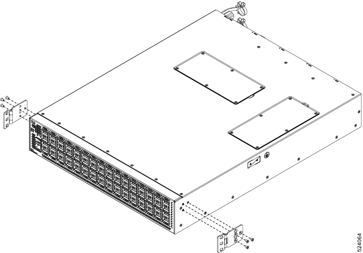
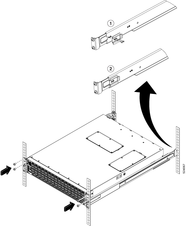
Installation Options with Rack-Mount Kits

The rack-mount kit enables you to install the switch into racks of varying depths. You can position the switch with easy access to either the port connections or the fan and power supply modules.

You can install the switch using the following rack-mount options:

The rack or cabinet that you use must meet the requirements listed the in General Requirements for Cabinets and Racks section.


Note


You are responsible for verifying that your rack and rack-mount hardware comply with the guidelines that are described in this doc.


Install a Rack

Before you install the switch, you must install a standard four-post, 19-inch EIA data center rack (or a cabinet that contains such a rack) that meets the requirements listed in Overview of Racks.

Procedure


Step 1

Bolt the rack to the concrete subfloor before moving the chassis onto it.

Warning


Statement 1048—Rack Stabilization

The rack stabilizing mechanism must be in place, or the rack must be bolted to the floor before installation or servicing. Failure to stabilize the rack can cause bodily injury.

Step 2

If the rack has bonded construction, connect it to the earth ground. This action enables you to easily ground the switch and its components and to ground your electrostatic discharge (ESD) wrist strap to prevent damaging discharges when you handle ungrounded components before installing them.

Step 3

Include one or two power sources at the rack. For AC power, provide a power receptacle. For DC power, provide a circuit breaker with terminals for connecting power cables.

Warning


Statement 1018—Supply Circuit

To reduce risk of electric shock and fire, take care when connecting units to the supply circuit so that wiring is not overloaded.

Note


If you are not using power redundancy or are using n+1 redundancy, you need only one power source. If you are using n+n redundancy, you need two power sources.


Unpacking and Inspecting a New Switch

Before you install a new chassis, you need to unpack and inspect it to be sure that you have all the items that you ordered and verify that the switch was not damaged during shipment. If anything is damaged or missing, contact your customer representative immediately.


Caution


When you handle the chassis or its components, you must follow ESD protocol at all times to prevent ESD damage. This protocol includes but is not limited to wearing an ESD wrist strap that you connect to the earth ground.


Tip


Do not discard the shipping container when you unpack the switch. Flatten the shipping cartons and store them. If you need to move or ship the system in the future, you will need this container.


Procedure


Step 1

Compare the shipment to the equipment list that is provided by your customer service representative and verify that you have received all of the ordered items.

The shipment should include the following:

  • Switch chassis, which includes the following installed components:

    • Two power supplies (any combination of the following with the airflow direction being the same as for the fan modules):

      • 1400-W AC power supply

        • Port-side exhaust AC power supply with blue coloring (NXA-PAC-1400W-PE)

        • Port-side intake AC power supply with burgundy coloring (NXA-PAC-1400W-PI)

      • 2000-W DC power supply

        • Port-side exhaust DC power supply with blue coloring (NXA-PDC-2KW-PE)

        • Port-side intake DC power supply with burgundy coloring (NXA-PDC-2KW-PI)

      • 2000-W HVAC/HVDC power supply

        • HVAC/HVDC DC airflow power intake with burgundy coloring (NXA-PHV-2KW-PI)

    • Four fan modules (all fan and power supply modules must have the same airflow direction)

      • Port-side exhaust airflow with blue coloring (NXASFAN-160CFM2PE)

      • Port-side intake airflow with burgundy coloring (NXASFAN-160CFM2PI)

  • Switch accessory kit

Step 2

Check the contents of the box for damage.

Step 3

If you notice any discrepancies or damage, send the following information to your customer service representative by email:

  • Invoice number of the shipper (see the packing slip)

  • Model and serial number of the missing or damaged unit

  • Description of the problem and how it affects the installation


Planning How to Position the Chassis in the Rack

The switch is designed so that you can have coolant air flow through the switch in one of the two following directions:

  • Enter the port side and exhaust out the power supply side (port-side intake airflow)

  • Enter the power supply side and exhaust out the port side (port-side exhaust airflow)

For port-side intake airflow, the switch must have port-side intake fan and AC power supply modules with one or more of the following colorings:

  • Red coloring on fan modules and AC power supplies

  • Red coloring on 2000-W HVAC/HVDC power supplies (power supplies with their airflow direction set by the fan modules)

  • Red coloring on DC power supply is also used for port-side-intake air flow.

For port-side exhaust airflow, the switch must have port-side exhaust fan and AC power supply modules with one or more of the following colorings:

  • Blue coloring on fan modules and AC power supplies

  • Blue coloring on DC power supplies

You can plan the positioning of the switch so that its ports are located close to ports on connected devices or so that the fan and power supply modules are conveniently located in a maintenance aisle, and then order the modules that move coolant air in the appropriate direction from the cold aisle to the hot aisle.


Note


All fan and power supply modules in the same switch must operate with the same direction of airflow and the air intake portion of the switch must be located in a cold aisle.


Installing the Switch using the NXK-ACC-RMK2-2RU Rack-Mount Kit

To install the switch, you must attach mounting brackets to the rack, install slider rails on the rear of the rack, slide the switch onto the slider rails, install the retainer brackets, and secure the switch to the rack with the retainer clips. Typically, the front of the rack is the side easiest to access for maintenance.


Note


You must supply the eight 10-32 or 12-24 screws required to mount the slider rails and switch to the rack.

Before you begin

  • You have inspected the switch shipment to ensure that you have everything ordered.

  • Make sure that the switch rack-mount kit includes the following parts:

    • Rack-mount brackets (2)

    • Rack-mount front-mount brackets (2)

    • Rack-mount slider rails (2)

    • Rack-mount retainer clips (2)

    • Phillips countersink screws (12)

    • Flat head screws M4 (6)

    • Flat head screws M3 (4)

  • The rack is installed and secured to its location.

Procedure


Step 1

Install two rack-mount brackets to the rack as follows:

  1. Determine which end of the chassis is to be located in the cold aisle as follows:

    • If the switch has port-side intake modules (fan modules with burgundy coloring), position the front-mount brackets so that the switch ports will be in the cold aisle.

    • If the switch has port-side exhaust modules (fan modules with blue coloring), position the front-mount brackets so that the switch fan and power supply modules will be in the cold aisle.

  2. Position a front-mount bracket so that it aligns to the desired position in the rack and secure the bracket with 12-24 screws or 10-32 screws, depending on the rack thread type (see the following figure). Tighten 12-24 screws to 30 in-lb (3.39 N·m) of torque and tighten 10-32 screws to 20 in-lb (2.26 N·m) of torque..

  3. Repeat Step 1 for the other front rack-mount bracket on the other side of the rack and be sure to position that bracket horizontally to the same level as first bracket.

Step 2

If you are not installing the chassis into a grounded rack, you must attach a customer-supplied grounding wire to the chassis as explained in Grounding the Chassis. If you are installing the chassis into a grounded rack, you can skip this step.

Step 3

Install the slider rails on the rack or cabinet as follows:

  1. Determine which two posts of the rack or cabinet you should use for the slider rails. Of the four vertical posts in the rack or cabinet, two will be used for the front mount brackets attached to the easiest accessed end of the chassis, and the other two posts will have the slider rails.

  2. Position a slider rail at the desired level on the back side of the rack and slide it into the front-mount bracket already installed and secure with 12-24 screws or 10-32 screws, depending on the rack thread type (see the following figure). Tighten 12-24 screws to 30 in-lb (3.39 N·m) of torque and tighten 10-32 screws to 20 in-lb (2.26 N·m) of torque.

  3. Repeat Step 3 to attach the other slider rail to the other side of the rack.

    To make sure that the slider rails are at the same level, you should use a level tool, tape measure, or carefully count the screw holes in the vertical mounting rails.

Step 4

Insert the switch into the rack and attach it as follows:

  1. Align the four holes in one side of front mount brackets to three holes on the left or right side of the chassis (see the following figure).

  2. Use three M4 x 6 mm screws to attach the bracket to the chassis. Tighten each screw to 11 to 15 in-lb (1.2 to 1.7 N·m).

  3. Repeat Steps 4 to attach the second front mount bracket to the other side of the chassis.

Step 5

Insert the switch into the rack and attach it as follows:

  1. Holding the switch with both hands, position the switch onto the rack-mount brackets and carefully slide the chassis into the rack (see the following figure).

Step 6

Rotate one front mount bracket to align with the rack (see the following figure).

  1. Tighten the 10-32 screws to 20 in-lb (2.26 N·m) or tighten the 12-24 screws to 30 in-lb (3.39 N·m).

  2. Repeat Step 6 to attach the other front mount bracket on other side of the chassis.

Step 7

Insert the retainer clip to hold the chassis in place.

  1. Align the retainer clip to the inside of the back of the slider rail. Make sure to hook the flange to the cutout on the bracket and align the screw holes (see the following figure).

  2. Attach the screws to secure the retainer clip (see the following figure).

  3. Repeat Step 7 to attach the other retainer clip on the other side of the chassis.

Step 8

If you attached a grounding wire to the chassis grounding pad, connect the other end of the wire to the facility ground.


Grounding the Chassis

The switch chassis is automatically grounded when you properly install the switch in a grounded rack with metal-to-metal connections between the switch and rack.


Note


Provide an electrical conducting path between the product chassis and the metal surface of the enclosure or rack in which it is mounted or to a grounding conductor. To ensure electrical continuity, use thread-forming type mounting screws that remove any paint or non-conductive coatings and establish a metal-to-metal contact. Remove any paint or other non-conductive coatings on the surfaces between the mounting hardware and the enclosure or rack. Clean the surfaces and apply an antioxidant before installation.


Ground the chassis, which is required if the rack is not grounded. Attach a customer-supplied grounding cable. Attach the cable to the chassis grounding pad and the facility ground.


Warning


Statement 1024—Ground Conductor

This equipment must be grounded. To reduce the risk of electric shock, never defeat the ground conductor or operate the equipment in the absence of a suitably installed ground conductor. Contact the appropriate electrical inspection authority or an electrician if you are uncertain that suitable grounding is available.


Warning


Statement 1046—Installing or Replacing the Unit

To reduce risk of electric shock, when installing or replacing the unit, the ground connection must always be made first and disconnected last.


Before you begin

Before you can ground the chassis, you must have a connection to the earth ground for the data center building.

Procedure


Step 1

Use a wire-stripping tool to remove approximately 0.75 inch (19 mm) of the covering from the end of the grounding wire. We recommend 6-AWG wire for the U.S. installations.

Step 2

Insert the stripped end of the grounding wire into the open end of the grounding lug. Use a crimping tool to crimp the lug to the wire, see the following figure. Verify that the ground wire is securely attached to the grounding lug by attempting to pull the wire out of the crimped lug.

1

Chassis grounding pad

3

2 M4 screws are used to secure the grounding lug to the chassis

2

Grounding cable, with 0.75 in. (19 mm) of insulation that is stripped from one end, which is inserted into the grounding lug and crimped in place

Step 3

Secure the grounding lug to the chassis grounding pad with two M4 screws, see the previous figure 1. Tighten the screws to 11 to 15 in-lb (1.24 to 1.69 N·m) of torque.

Step 4

Prepare the other end of the grounding wire and connect it to the facility ground.


Starting the Switch

You start the switch by connecting it to its dedicated power source. If you need n+n redundancy, you must connect each power supply in a switch to a different power source.


Note


This equipment is designed to boot up in less than 30 minutes, dependent on its neighboring devices being fully up and running.


Before you begin

  • The switch must be installed and secured to a rack or cabinet.

  • The switch must be adequately grounded.

  • The rack must be close enough to the dedicated power source so that you can connect the switch to the power source by using the designated power cables.

  • You have the designated power cables for the power supplies that you are connecting to the dedicated power sources.


    Note


    Depending on the outlet receptacle on your AC power distribution unit, you might need an optional jumper power cord to connect the switch to your outlet receptacle.


  • The switch is not connected to the network (this includes any management or interface connections).

  • The fan and power supply modules are fully secured in their chassis slots.

Procedure


Step 1

For any AC power supply:

  1. Using the recommended AC power cable for your country or region, connect one end to the AC power supply.

  2. Connect the other end of the power cable to the AC power source.

Step 2

For any HVAC/HVDC power supply, connect it to a power source as follows:

  1. Using the recommended high voltage power cable for your country or region, connect the Anderson Power Saf-D-Grid connector on the power cable to the power receptacle on the power supply. Make sure that the connector clicks when fully pushed into the receptacle.

  2. Connect the other end of the power cable to a power source.

    • When connecting to an HVAC power source, insert the plug in a receptacle for the HVAC power source.

    • When connecting to an HVDC power source, do the following:

      1. Verify that the power is turned off at a circuit breaker for the power source terminals.

      2. Remove the nuts from each of the terminal posts for the power supply.

      3. Place the power cable negative-wire terminal ring on the negative terminal for the power source and secure them with a terminal nut.

      4. Place the power cable positive-wire terminal ring on the positive terminal for the power source and secure them with a terminal nut.

      5. Place the power cable ground-wire terminal ring on the ground terminal for the power source and secure them with a terminal nut.

      6. If there is a safety cover for the power source terminals, place and secure it over the terminals to avoid an electrical shock hazard.

      7. Turn on the power at the power source circuit breaker.

Step 3

For any DC power supply, do the following:

  1. Turn off the circuit breaker for the power source to avoid an electrical shock hazard.

  2. Verify that the power cable wires from the power source are connected to a connector block.

  3. Insert the connector block into the receptacle on the power supply. Make sure that the connector block clicks when fully inserted in the receptacle and does not pull out.

  4. If there is a safety cover for the terminals, place and secure it over the terminals to avoid an electrical shock hazard.

  5. Turn on the power at the circuit breaker for the DC power source.

Step 4

Verify that the power supply LED is on and green.

Step 5

Listen for the fans; they should begin operating when the power supply is powered.

Step 6

After the switch boots, verify that the following LEDs are lit:

  • On the fan modules, the Status (STA or STS) LED is green.

    If a fan module Status LED is not green, try reinstalling the fan module.

  • After initialization, the switch chassis Status (labeled as STA or STS) LED is green.

Step 7

Verify that the system software has booted and the switch has initialized without error messages.

A setup utility automatically launches the first time that you access the switch and guides you through the basic configuration. For instructions on how to configure the switch and check module connectivity, see the appropriate Cisco Nexus 9000 Series configuration guide.