Configuring Port-Based Traffic Control

Overview of Port-Based Traffic Control

Port-based traffic control is a set of Layer 2 features on the Cisco Catalyst switches used to filter or block packets at the port level in response to specific traffic conditions. The following port-based traffic control features are supported in the Cisco IOS Release for which this guide is written:
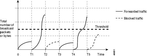
  • Storm Control

  • Protected Ports

  • Port Blocking

  • Port Security

  • Protocol Storm Protection

Configuring Storm Control

Information About Storm Control

Storm Control

Storm control prevents traffic on a LAN from being disrupted by a broadcast, multicast, or unicast storm on one of the physical interfaces. A LAN storm occurs when packets flood the LAN, creating excessive traffic and degrading network performance. Errors in the protocol-stack implementation, mistakes in network configurations, or users issuing a denial-of-service attack can cause a storm.

Storm control (or traffic suppression) monitors packets passing from an interface to the switching bus and determines if the packet is unicast, multicast, or broadcast. The switch counts the number of packets of a specified type received within the 1-second time interval and compares the measurement with a predefined suppression-level threshold.

How Traffic Activity is Measured

Storm control uses one of these methods to measure traffic activity:

  • Bandwidth as a percentage of the total available bandwidth of the port that can be used by the broadcast, multicast, or unicast traffic

  • Traffic rate in packets per second at which broadcast, multicast, or unicast packets are received

  • Traffic rate in bits per second at which broadcast, multicast, or unicast packets are received

  • Traffic rate in packets per second and for small frames. This feature is enabled globally. The threshold for small frames is configured for each interface.

With each method, the port blocks traffic when the rising threshold is reached. The port remains blocked until the traffic rate drops below the falling threshold (if one is specified) and then resumes normal forwarding. If the falling suppression level is not specified, the switch blocks all traffic until the traffic rate drops below the rising suppression level. In general, the higher the level, the less effective the protection against broadcast storms.


Note

When the storm control threshold for multicast traffic is reached, all multicast traffic except control traffic, such as bridge protocol data unit (BDPU) and Cisco Discovery Protocol (CDP) frames, are blocked. However, the switch does not differentiate between routing updates, such as OSPF, and regular multicast data traffic, so both types of traffic are blocked.


Traffic Patterns

Figure 1. Broadcast Storm Control Example. This example shows broadcast traffic patterns on an interface over a given period of time.

Broadcast traffic being forwarded exceeded the configured threshold between time intervals T1 and T2 and between T4 and T5. When the amount of specified traffic exceeds the threshold, all traffic of that kind is dropped for the next time period. Therefore, broadcast traffic is blocked during the intervals following T2 and T5. At the next time interval (for example, T3), if broadcast traffic does not exceed the threshold, it is again forwarded.

The combination of the storm-control suppression level and the 1-second time interval controls the way the storm control algorithm works. A higher threshold allows more packets to pass through. A threshold value of 100 percent means that no limit is placed on the traffic. A value of 0.0 means that all broadcast, multicast, or unicast traffic on that port is blocked.


Note

Because packets do not arrive at uniform intervals, the 1-second time interval during which traffic activity is measured can affect the behavior of storm control.


You use the storm-control interface configuration commands to set the threshold value for each traffic type.

How to Configure Storm Control

Configuring Storm Control and Threshold Levels

You configure storm control on a port and enter the threshold level that you want to be used for a particular type of traffic.

However, because of hardware limitations and the way in which packets of different sizes are counted, threshold percentages are approximations. Depending on the sizes of the packets making up the incoming traffic, the actual enforced threshold might differ from the configured level by several percentage points.


Note

Storm control is supported on physical interfaces. You can also configure storm control on an EtherChannel. When storm control is configured on an EtherChannel, the storm control settings propagate to the EtherChannel physical interfaces.

Follow these steps to storm control and threshold levels:

Before you begin

Storm control is supported on physical interfaces. You can also configure storm control on an EtherChannel. When storm control is configured on an EtherChannel, the storm control settings propagate to the EtherChannel physical interfaces.

SUMMARY STEPS

  1. enable
  2. configure terminal
  3. interface interface-id
  4. storm-control {broadcast | multicast | unicast} level {level [level-low] | bps bps [bps-low] | pps pps [pps-low]}
  5. storm-control action {shutdown | trap}
  6. end
  7. show storm-control [interface-id] [broadcast | multicast | unicast]
  8. copy running-config startup-config

DETAILED STEPS

  Command or Action Purpose
Step 1

enable

Example:

Switch> enable

Enables privileged EXEC mode.

  • Enter your password if prompted.

Step 2

configure terminal

Example:

Switch# configure terminal

Enters global configuration mode.

Step 3

interface interface-id

Example:

Switch(config)# interface gigabitethernet1/0/1

Specifies the interface to be configured, and enter interface configuration mode.

Step 4

storm-control {broadcast | multicast | unicast} level {level [level-low] | bps bps [bps-low] | pps pps [pps-low]}

Example:

Switch(config-if)# storm-control unicast level 87 65

Configures broadcast, multicast, or unicast storm control. By default, storm control is disabled.

The keywords have these meanings:

  • For level , specifies the rising threshold level for broadcast, multicast, or unicast traffic as a percentage (up to two decimal places) of the bandwidth. The port blocks traffic when the rising threshold is reached. The range is 0.00 to 100.00.

  • (Optional) For level-low , specifies the falling threshold level as a percentage (up to two decimal places) of the bandwidth. This value must be less than or equal to the rising suppression value. The port forwards traffic when traffic drops below this level. If you do not configure a falling suppression level, it is set to the rising suppression level. The range is 0.00 to 100.00.

    If you set the threshold to the maximum value (100 percent), no limit is placed on the traffic. If you set the threshold to 0.0, all broadcast, multicast, and unicast traffic on that port is blocked.

  • For bps bps , specifies the rising threshold level for broadcast, multicast, or unicast traffic in bits per second (up to one decimal place). The port blocks traffic when the rising threshold is reached. The range is 0.0 to 10000000000.0.

  • (Optional) For bps-low , specifies the falling threshold level in bits per second (up to one decimal place). It can be less than or equal to the rising threshold level. The port forwards traffic when traffic drops below this level. The range is 0.0 to 10000000000.0.

  • For pps pps , specifies the rising threshold level for broadcast, multicast, or unicast traffic in packets per second (up to one decimal place). The port blocks traffic when the rising threshold is reached. The range is 0.0 to 10000000000.0.

  • (Optional) For pps-low , specifies the falling threshold level in packets per second (up to one decimal place). It can be less than or equal to the rising threshold level. The port forwards traffic when traffic drops below this level. The range is 0.0 to 10000000000.0.

For BPS and PPS settings, you can use metric suffixes such as k, m, and g for large number thresholds.

Step 5

storm-control action {shutdown | trap}

Example:

Switch(config-if)# storm-control action trap

Specifies the action to be taken when a storm is detected. The default is to filter out the traffic and not to send traps.

  • Select the shutdown keyword to error-disable the port during a storm.

  • Select the trap keyword to generate an SNMP trap when a storm is detected.

Step 6

end

Example:

Switch(config-if)# end

Returns to privileged EXEC mode.

Step 7

show storm-control [interface-id] [broadcast | multicast | unicast]

Example:

Switch# show storm-control gigabitethernet1/0/1 unicast

Verifies the storm control suppression levels set on the interface for the specified traffic type. If you do not enter a traffic type, broadcast storm control settings are displayed.

Step 8

copy running-config startup-config

Example:

Switch# copy running-config startup-config

(Optional) Saves your entries in the configuration file.

Configuring Small-Frame Arrival Rate

Incoming VLAN-tagged packets smaller than 67 bytes are considered small frames. They are forwarded by the switch, but they do not cause the switch storm-control counters to increment.

You globally enable the small-frame arrival feature on the switch and then configure the small-frame threshold for packets on each interface. Packets smaller than the minimum size and arriving at a specified rate (the threshold) are dropped since the port is error disabled.

SUMMARY STEPS

  1. enable
  2. configure terminal
  3. errdisable detect cause small-frame
  4. errdisable recovery interval interval
  5. errdisable recovery cause small-frame
  6. interface interface-id
  7. small-frame violation-rate pps
  8. end
  9. show interfaces interface-id
  10. show running-config
  11. copy running-config startup-config

DETAILED STEPS

  Command or Action Purpose
Step 1

enable

Example:

Switch> enable

Enables privileged EXEC mode.

  • Enter your password if prompted.

Step 2

configure terminal

Example:

Switch# configure terminal

Enters global configuration mode.

Step 3

errdisable detect cause small-frame

Example:

Switch(config)# errdisable detect cause small-frame

Enables the small-frame rate-arrival feature on the switch.

Step 4

errdisable recovery interval interval

Example:

Switch(config)# errdisable recovery interval 60

(Optional) Specifies the time to recover from the specified error-disabled state.

Step 5

errdisable recovery cause small-frame

Example:

Switch(config)# errdisable recovery cause small-frame

(Optional) Configures the recovery time for error-disabled ports to be automatically re-enabled after they are error disabled by the arrival of small frames

Storm control is supported on physical interfaces. You can also configure storm control on an EtherChannel. When storm control is configured on an EtherChannel, the storm control settings propagate to the EtherChannel physical interfaces.

Step 6

interface interface-id

Example:

Switch(config)# interface gigabitethernet1/0/2

Enters interface configuration mode, and specify the interface to be configured.

Step 7

small-frame violation-rate pps

Example:

Switch(config-if)# small-frame violation rate 10000

Configures the threshold rate for the interface to drop incoming packets and error disable the port. The range is 1 to 10,000 packets per second (pps)

Step 8

end

Example:

Switch(config)# end

Returns to privileged EXEC mode.

Step 9

show interfaces interface-id

Example:

Switch# show interfaces gigabitethernet1/0/2

Verifies the configuration.

Step 10

show running-config

Example:

Switch# show running-config 

Verifies your entries.

Step 11

copy running-config startup-config

Example:

Switch# copy running-config startup-config 

(Optional) Saves your entries in the configuration file.

Configuration Examples for Configuring Storm Control

Example: Configuring Storm Control and Threshold Levels

This example shows how to enable broadcast address storm control on a port to a level of 20 percent. When the broadcast traffic exceeds the configured level of 20 percent of the total available bandwidth of the port within the traffic-storm-control interval, the switch drops all broadcast traffic until the end of the traffic-storm-control interval:


Switch# configure terminal
Switch(config)# interface gigabitethernet1/0/1
Switch(config-if)# storm-control broadcast level 20

Configuring Protected Ports

Information About Protected Ports

Protected Ports

Some applications require that no traffic be forwarded at Layer 2 between ports on the same switch so that one neighbor does not see the traffic generated by another neighbor. In such an environment, the use of protected ports ensures that there is no exchange of unicast, broadcast, or multicast traffic between these ports on the switch.

Protected ports have these features:

  • A protected port does not forward any traffic (unicast, multicast, or broadcast) to any other port that is also a protected port. Data traffic cannot be forwarded between protected ports at Layer 2; only control traffic, such as PIM packets, is forwarded because these packets are processed by the CPU and forwarded in software. All data traffic passing between protected ports must be forwarded through a Layer 3 device.

  • Forwarding behavior between a protected port and a nonprotected port proceeds as usual.

Default Protected Port Configuration

The default is to have no protected ports defined.

Protected Ports Guidelines

You can configure protected ports on a physical interface (for example, Gigabit Ethernet port 1) or an EtherChannel group (for example, port-channel 5). When you enable protected ports for a port channel, it is enabled for all ports in the port-channel group.

How to Configure Protected Ports

Configuring a Protected Port

Before you begin

Protected ports are not pre-defined. This is the task to configure one.

SUMMARY STEPS

  1. enable
  2. configure terminal
  3. interface interface-id
  4. switchport protected
  5. end
  6. show interfaces interface-id switchport
  7. show running-config
  8. copy running-config startup-config

DETAILED STEPS

  Command or Action Purpose
Step 1

enable

Example:


Switch> enable

Enables privileged EXEC mode.

  • Enter your password if prompted.

Step 2

configure terminal

Example:


Switch# configure terminal

Enters global configuration mode.

Step 3

interface interface-id

Example:


Switch(config)# interface gigabitethernet1/0/1

Specifies the interface to be configured, and enter interface configuration mode.

Step 4

switchport protected

Example:


Switch(config-if)# switchport protected

Configures the interface to be a protected port.

Step 5

end

Example:


Switch(config)# end

Returns to privileged EXEC mode.

Step 6

show interfaces interface-id switchport

Example:


Switch# show interfaces gigabitethernet1/0/1 switchport

Verifies your entries.

Step 7

show running-config

Example:


Switch# show running-config 

Verifies your entries.

Step 8

copy running-config startup-config

Example:


Switch# copy running-config startup-config 

(Optional) Saves your entries in the configuration file.

Configuring Port Blocking

Information About Port Blocking

Port Blocking

By default, the switch floods packets with unknown destination MAC addresses out of all ports. If unknown unicast and multicast traffic is forwarded to a protected port, there could be security issues. To prevent unknown unicast or multicast traffic from being forwarded from one port to another, you can block a port (protected or nonprotected) from flooding unknown unicast or multicast packets to other ports.


Note

With multicast traffic, the port blocking feature blocks only pure Layer 2 packets. Multicast packets that contain IPv4 or IPv6 information in the header are not blocked.


How to Configure Port Blocking

Blocking Flooded Traffic on an Interface

Before you begin

The interface can be a physical interface or an EtherChannel group. When you block multicast or unicast traffic for a port channel, it is blocked on all ports in the port-channel group.

SUMMARY STEPS

  1. enable
  2. configure terminal
  3. interface interface-id
  4. switchport block multicast
  5. switchport block unicast
  6. end
  7. show interfaces interface-id switchport
  8. show running-config
  9. copy running-config startup-config

DETAILED STEPS

  Command or Action Purpose
Step 1

enable

Example:


Switch> enable

Enables privileged EXEC mode.

  • Enter your password if prompted.

Step 2

configure terminal

Example:


Switch# configure terminal

Enters global configuration mode.

Step 3

interface interface-id

Example:


Switch(config)# interface gigabitethernet1/0/1

Specifies the interface to be configured, and enter interface configuration mode.

Step 4

switchport block multicast

Example:


Switch(config-if)# switchport block multicast

Blocks unknown multicast forwarding out of the port.

Step 5

switchport block unicast

Example:


Switch(config-if)# switchport block unicast

Blocks unknown unicast forwarding out of the port.

Step 6

end

Example:


Switch(config)# end

Returns to privileged EXEC mode.

Step 7

show interfaces interface-id switchport

Example:


Switch# show interfaces gigabitethernet1/0/1 switchport

Verifies your entries.

Step 8

show running-config

Example:


Switch# show running-config 

Verifies your entries.

Step 9

copy running-config startup-config

Example:


Switch# copy running-config startup-config 

(Optional) Saves your entries in the configuration file.

Configuring Port Security

Prerequisites for Port Security


Note

If you try to set the maximum value to a number less than the number of secure addresses already configured on an interface, the command is rejected.


Restrictions for Port Security

The maximum number of secure MAC addresses that you can configure on a switch is set by the maximum number of available MAC addresses allowed in the system. This number is the total of available MAC addresses, including those used for other Layer 2 functions and any other secure MAC addresses configured on interfaces.

Information About Port Security

Port Security

You can use the port security feature to restrict input to an interface by limiting and identifying MAC addresses of the stations allowed to access the port. When you assign secure MAC addresses to a secure port, the port does not forward packets with source addresses outside the group of defined addresses. If you limit the number of secure MAC addresses to one and assign a single secure MAC address, the workstation attached to that port is assured the full bandwidth of the port.

If a port is configured as a secure port and the maximum number of secure MAC addresses is reached, when the MAC address of a station attempting to access the port is different from any of the identified secure MAC addresses, a security violation occurs. Also, if a station with a secure MAC address configured or learned on one secure port attempts to access another secure port, a violation is flagged.

Types of Secure MAC Addresses

The switch supports these types of secure MAC addresses:

  • Static secure MAC addresses—These are manually configured by using the switchport port-security mac-address mac-address interface configuration command, stored in the address table, and added to the switch running configuration.

  • Dynamic secure MAC addresses—These are dynamically configured, stored only in the address table, and removed when the switch restarts.

  • Sticky secure MAC addresses—These can be dynamically learned or manually configured, stored in the address table, and added to the running configuration. If these addresses are saved in the configuration file, when the switch restarts, the interface does not need to dynamically reconfigure them.

Sticky Secure MAC Addresses

You can configure an interface to convert the dynamic MAC addresses to sticky secure MAC addresses and to add them to the running configuration by enabling sticky learning. The interface converts all the dynamic secure MAC addresses, including those that were dynamically learned before sticky learning was enabled, to sticky secure MAC addresses. All sticky secure MAC addresses are added to the running configuration.

The sticky secure MAC addresses do not automatically become part of the configuration file, which is the startup configuration used each time the switch restarts. If you save the sticky secure MAC addresses in the configuration file, when the switch restarts, the interface does not need to relearn these addresses. If you do not save the sticky secure addresses, they are lost.

If sticky learning is disabled, the sticky secure MAC addresses are converted to dynamic secure addresses and are removed from the running configuration.

Security Violations

It is a security violation when one of these situations occurs:

  • The maximum number of secure MAC addresses have been added to the address table, and a station whose MAC address is not in the address table attempts to access the interface.

  • An address learned or configured on one secure interface is seen on another secure interface in the same VLAN.

  • Running diagnostic tests with port security enabled.

You can configure the interface for one of three violation modes, based on the action to be taken if a violation occurs:

  • protect—when the number of secure MAC addresses reaches the maximum limit allowed on the port, packets with unknown source addresses are dropped until you remove a sufficient number of secure MAC addresses to drop below the maximum value or increase the number of maximum allowable addresses. You are not notified that a security violation has occurred.


    Note

    We do not recommend configuring the protect violation mode on a trunk port. The protect mode disables learning when any VLAN reaches its maximum limit, even if the port has not reached its maximum limit.


  • restrict—when the number of secure MAC addresses reaches the maximum limit allowed on the port, packets with unknown source addresses are dropped until you remove a sufficient number of secure MAC addresses to drop below the maximum value or increase the number of maximum allowable addresses. In this mode, you are notified that a security violation has occurred. An SNMP trap is sent, a syslog message is logged, and the violation counter increments.

  • shutdown—a port security violation causes the interface to become error-disabled and to shut down immediately, and the port LED turns off. When a secure port is in the error-disabled state, you can bring it out of this state by entering the errdisable recovery cause psecure-violation global configuration command, or you can manually re-enable it by entering the shutdown and no shut down interface configuration commands. This is the default mode.

  • shutdown vlan—Use to set the security violation mode per-VLAN. In this mode, the VLAN is error disabled instead of the entire port when a violation occurs

This table shows the violation mode and the actions taken when you configure an interface for port security.

Table 1. Security Violation Mode Actions

Violation Mode

Traffic is forwarded

1

Sends SNMP trap

Sends syslog message

Displays error message

2

Violation counter increments

Shuts down port

protect

No

No

No

No

No

No

restrict

No

Yes

Yes

No

Yes

No

shutdown

No

No

No

No

Yes

Yes

shutdown vlan

No

No

Yes

No

Yes

No

3
1 Packets with unknown source addresses are dropped until you remove a sufficient number of secure MAC addresses.
2 The switch returns an error message if you manually configure an address that would cause a security violation.
3 Shuts down only the VLAN on which the violation occurred.

Default Port Security Configuration

Table 2. Default Port Security Configuration

Feature

Default Setting

Port security

Disabled on a port.

Sticky address learning

Disabled.

Maximum number of secure MAC addresses per port

1.

Violation mode

Shutdown. The port shuts down when the maximum number of secure MAC addresses is exceeded.

Port security aging

Disabled. Aging time is 0.

Static aging is disabled.

Type is absolute.

Port Security Configuration Guidelines

  • Port security can only be configured on static access ports or trunk ports. A secure port cannot be a dynamic access port.

  • A secure port cannot be a destination port for Switched Port Analyzer (SPAN).


  • Note

    Voice VLAN is only supported on access ports and not on trunk ports, even though the configuration is allowed.


  • When you enable port security on an interface that is also configured with a voice VLAN, set the maximum allowed secure addresses on the port to two. When the port is connected to a Cisco IP phone, the IP phone requires one MAC address. The Cisco IP phone address is learned on the voice VLAN, but is not learned on the access VLAN. If you connect a single PC to the Cisco IP phone, no additional MAC addresses are required. If you connect more than one PC to the Cisco IP phone, you must configure enough secure addresses to allow one for each PC and one for the phone.

  • When a trunk port configured with port security and assigned to an access VLAN for data traffic and to a voice VLAN for voice traffic, entering the switchport voice and switchport priority extend interface configuration commands has no effect.

    When a connected device uses the same MAC address to request an IP address for the access VLAN and then an IP address for the voice VLAN, only the access VLAN is assigned an IP address.

  • When you enter a maximum secure address value for an interface, and the new value is greater than the previous value, the new value overwrites the previously configured value. If the new value is less than the previous value and the number of configured secure addresses on the interface exceeds the new value, the command is rejected.

  • The switch does not support port security aging of sticky secure MAC addresses.

This table summarizes port security compatibility with other port-based features.

Table 3. Port Security Compatibility with Other Switch Features

Type of Port or Feature on Port

Compatible with Port Security

DTP 4 port 5

No

Trunk port

Yes

Dynamic-access port 6

No

Routed port

No

SPAN source port

Yes

SPAN destination port

No

EtherChannel

Yes

Tunneling port

Yes

Protected port

Yes

IEEE 802.1x port

Yes

Voice VLAN port 7

Yes

IP source guard

Yes

Dynamic Address Resolution Protocol (ARP) inspection

Yes

Flex Links

Yes

4 DTP=Dynamic Trunking Protocol
5 A port configured with the switchport mode dynamic interface configuration command.
6 A VLAN Query Protocol (VQP) port configured with the switchport access vlan dynamic interface configuration command.
7 You must set the maximum allowed secure addresses on the port to two plus the maximum number of secure addresses allowed on the access VLAN.

Port Security Aging

You can use port security aging to set the aging time for all secure addresses on a port. Two types of aging are supported per port:

  • Absolute—The secure addresses on the port are deleted after the specified aging time.

  • Inactivity—The secure addresses on the port are deleted only if the secure addresses are inactive for the specified aging time.

Port Security and Switch Stacks

When a switch joins a stack, the new switch will get the configured secure addresses. All dynamic secure addresses are downloaded by the new stack member from the other stack members.

When a switch (either the active switch or a stack member) leaves the stack, the remaining stack members are notified, and the secure MAC addresses configured or learned by that switch are deleted from the secure MAC address table.

How to Configure Port Security

Enabling and Configuring Port Security

Before you begin

This task restricts input to an interface by limiting and identifying MAC addresses of the stations allowed to access the port:

SUMMARY STEPS

  1. enable
  2. configure terminal
  3. interface interface-id
  4. switchport mode {access | trunk}
  5. switchport voice vlan vlan-id
  6. switchport port-security
  7. switchport port-security [maximum value [vlan {vlan-list | {access | voice}}]]
  8. switchport port-security violation {protect | restrict | shutdown | shutdown vlan}
  9. switchport port-security [mac-address mac-address [vlan {vlan-id | {access | voice}}]
  10. switchport port-security mac-address sticky
  11. switchport port-security mac-address sticky [mac-address | vlan {vlan-id | {access | voice}}]
  12. end
  13. show port-security
  14. show running-config
  15. copy running-config startup-config

DETAILED STEPS

  Command or Action Purpose
Step 1

enable

Example:

Switch> enable

Enables privileged EXEC mode.

  • Enter your password if prompted.

Step 2

configure terminal

Example:

Switch# configure terminal

Enters global configuration mode.

Step 3

interface interface-id

Example:

Switch(config)# interface gigabitethernet1/0/1

Specifies the interface to be configured, and enter interface configuration mode.

Step 4

switchport mode {access | trunk}

Example:

Switch(config-if)# switchport mode access

Sets the interface switchport mode as access or trunk; an interface in the default mode (dynamic auto) cannot be configured as a secure port.

Step 5

switchport voice vlan vlan-id

Example:

Switch(config-if)# switchport voice vlan 22

Enables voice VLAN on a port.

vlan-id—Specifies the VLAN to be used for voice traffic.

Step 6

switchport port-security

Example:

Switch(config-if)# switchport port-security

Enable port security on the interface.

Step 7

switchport port-security [maximum value [vlan {vlan-list | {access | voice}}]]

Example:

Switch(config-if)# switchport port-security maximum 20

(Optional) Sets the maximum number of secure MAC addresses for the interface. The maximum number of secure MAC addresses that you can configure on a switch or switch stack is set by the maximum number of available MAC addresses allowed in the system. This number is the total of available MAC addresses, including those used for other Layer 2 functions and any other secure MAC addresses configured on interfaces.

(Optional) vlan —sets a per-VLAN maximum value

Enter one of these options after you enter the vlan keyword:

  • vlan-list —On a trunk port, you can set a per-VLAN maximum value on a range of VLANs separated by a hyphen or a series of VLANs separated by commas. For nonspecified VLANs, the per-VLAN maximum value is used.

  • access —On an access port, specifies the VLAN as an access VLAN.

  • voice —On an access port, specifies the VLAN as a voice VLAN.

Note 

The voice keyword is available only if a voice VLAN is configured on a port and if that port is not the access VLAN. If an interface is configured for voice VLAN, configure a maximum of two secure MAC addresses.

Step 8

switchport port-security violation {protect | restrict | shutdown | shutdown vlan}

Example:

Switch(config-if)# switchport port-security violation restrict

(Optional) Sets the violation mode, the action to be taken when a security violation is detected, as one of these:

  • protect —When the number of port secure MAC addresses reaches the maximum limit allowed on the port, packets with unknown source addresses are dropped until you remove a sufficient number of secure MAC addresses to drop below the maximum value or increase the number of maximum allowable addresses. You are not notified that a security violation has occurred.

    Note 

    We do not recommend configuring the protect mode on a trunk port. The protect mode disables learning when any VLAN reaches its maximum limit, even if the port has not reached its maximum limit.

  • restrict —When the number of secure MAC addresses reaches the limit allowed on the port, packets with unknown source addresses are dropped until you remove a sufficient number of secure MAC addresses or increase the number of maximum allowable addresses. An SNMP trap is sent, a syslog message is logged, and the violation counter increments.

  • shutdown —The interface is error-disabled when a violation occurs, and the port LED turns off. An SNMP trap is sent, a syslog message is logged, and the violation counter increments.

  • shutdown vlan —Use to set the security violation mode per VLAN. In this mode, the VLAN is error disabled instead of the entire port when a violation occurs.
    Note 

    When a secure port is in the error-disabled state, you can bring it out of this state by entering the errdisable recovery cause psecure-violation global configuration command. You can manually re-enable it by entering the shutdown and no shutdown interface configuration commands or by using the clear errdisable interface vlan privileged EXEC command.

Step 9

switchport port-security [mac-address mac-address [vlan {vlan-id | {access | voice}}]

Example:

Switch(config-if)# switchport port-security mac-address 00:A0:C7:12:C9:25 vlan 3 voice

(Optional) Enters a secure MAC address for the interface. You can use this command to enter the maximum number of secure MAC addresses. If you configure fewer secure MAC addresses than the maximum, the remaining MAC addresses are dynamically learned.

Note 

If you enable sticky learning after you enter this command, the secure addresses that were dynamically learned are converted to sticky secure MAC addresses and are added to the running configuration.

(Optional) vlan —sets a per-VLAN maximum value.

Enter one of these options after you enter the vlan keyword:

  • vlan-id —On a trunk port, you can specify the VLAN ID and the MAC address. If you do not specify a VLAN ID, the native VLAN is used.

  • access —On an access port, specifies the VLAN as an access VLAN.

  • voice —On an access port, specifies the VLAN as a voice VLAN.

Note 

The voice keyword is available only if a voice VLAN is configured on a port and if that port is not the access VLAN. If an interface is configured for voice VLAN, configure a maximum of two secure MAC addresses.

Step 10

switchport port-security mac-address sticky

Example:

Switch(config-if)# switchport port-security mac-address sticky

(Optional) Enables sticky learning on the interface.

Step 11

switchport port-security mac-address sticky [mac-address | vlan {vlan-id | {access | voice}}]

Example:

Switch(config-if)# switchport port-security mac-address sticky 00:A0:C7:12:C9:25 vlan voice

(Optional) Enters a sticky secure MAC address, repeating the command as many times as necessary. If you configure fewer secure MAC addresses than the maximum, the remaining MAC addresses are dynamically learned, are converted to sticky secure MAC addresses, and are added to the running configuration.

Note 

If you do not enable sticky learning before this command is entered, an error message appears, and you cannot enter a sticky secure MAC address.

(Optional) vlan —sets a per-VLAN maximum value.

Enter one of these options after you enter the vlan keyword:

  • vlan-id —On a trunk port, you can specify the VLAN ID and the MAC address. If you do not specify a VLAN ID, the native VLAN is used.

  • access —On an access port, specifies the VLAN as an access VLAN.

  • voice —On an access port, specifies the VLAN as a voice VLAN.

Note 

The voice keyword is available only if a voice VLAN is configured on a port and if that port is not the access VLAN.

Step 12

end

Example:

Switch(config)# end

Returns to privileged EXEC mode.

Step 13

show port-security

Example:

Switch# show port-security

Verifies your entries.

Step 14

show running-config

Example:

Switch# show running-config 

Verifies your entries.

Step 15

copy running-config startup-config

Example:

Switch# copy running-config startup-config 

(Optional) Saves your entries in the configuration file.

Enabling and Configuring Port Security Aging

Use this feature to remove and add devices on a secure port without manually deleting the existing secure MAC addresses and to still limit the number of secure addresses on a port. You can enable or disable the aging of secure addresses on a per-port basis.

SUMMARY STEPS

  1. enable
  2. configure terminal
  3. interface interface-id
  4. switchport port-security aging {static | time time | type {absolute | inactivity}}
  5. end
  6. show port-security [interface interface-id] [address]
  7. show running-config
  8. copy running-config startup-config

DETAILED STEPS

  Command or Action Purpose
Step 1

enable

Example:

Switch> enable

Enables privileged EXEC mode.

  • Enter your password if prompted.

Step 2

configure terminal

Example:

Switch# configure terminal

Enters global configuration mode.

Step 3

interface interface-id

Example:

Switch(config)# interface gigabitethernet1/0/1

Specifies the interface to be configured, and enter interface configuration mode.

Step 4

switchport port-security aging {static | time time | type {absolute | inactivity}}

Example:

Switch(config-if)# switchport port-security aging time 120

Enables or disable static aging for the secure port, or set the aging time or type.

Note 

The switch does not support port security aging of sticky secure addresses.

Enter static to enable aging for statically configured secure addresses on this port.

For time , specifies the aging time for this port. The valid range is from 0 to 1440 minutes.

For type , select one of these keywords:

  • absolute —Sets the aging type as absolute aging. All the secure addresses on this port age out exactly after the time (minutes) specified lapses and are removed from the secure address list.

  • inactivity —Sets the aging type as inactivity aging. The secure addresses on this port age out only if there is no data traffic from the secure source addresses for the specified time period.

Step 5

end

Example:

Switch(config)# end

Returns to privileged EXEC mode.

Step 6

show port-security [interface interface-id] [address]

Example:

Switch# show port-security interface gigabitethernet1/0/1

Verifies your entries.

Step 7

show running-config

Example:

Switch# show running-config 

Verifies your entries.

Step 8

copy running-config startup-config

Example:

Switch# copy running-config startup-config 

(Optional) Saves your entries in the configuration file.

Configuration Examples for Configuring Port Security

Example: Enabling and Configuring Port Security

This example shows how to enable port security on a port and to set the maximum number of secure addresses to 50. The violation mode is the default, no static secure MAC addresses are configured, and sticky learning is enabled.


Switch(config)# interface gigabitethernet1/0/1
Switch(config-if)# switchport mode access
Switch(config-if)# switchport port-security
Switch(config-if)# switchport port-security maximum 50
Switch(config-if)# switchport port-security mac-address sticky

This example shows how to configure a static secure MAC address on VLAN 3 on a port:


Switch(config)# interface gigabitethernet1/0/2
Switch(config-if)# switchport mode trunk
Switch(config-if)# switchport port-security
Switch(config-if)# switchport port-security mac-address 0000.02000.0004 vlan 3

This example shows how to configure a static secure MAC address on VLAN 3 on a port:


Switch(config)# interface tengigabitethernet1/0/1
Switch(config-if)# switchport access vlan 21
Switch(config-if)# switchport mode access
Switch(config-if)# switchport access vlan 22
Switch(config-if)# switchport port-security
Switch(config-if)# switchport port-security maximum 20
Switch(config-if)# switchport port-security violation restrict
Switch(config-if)# switchport port-security mac-address sticky
Switch(config-if)# switchport port-security mac-address sticky 0000.0000.0002
Switch(config-if)# switchport port-security mac-address 0000.0000.0003
Switch(config-if)# switchport port-security mac-address sticky 0000.0000.0001 vlan voice
Switch(config-if)# switchport port-security mac-address 0000.0000.0004 vlan voice
Switch(config-if)# switchport port-security maximum 10 vlan access
Switch(config-if)# switchport port-security maximum 10 vlan voice

Example: Enabling and Configuring Port Security Aging

This example shows how to set the aging time as 2 minutes for the inactivity aging type with aging enabled for the configured secure addresses on the interface:


Switch(config-if)# switchport port-security aging time 2
Switch(config-if)# switchport port-security aging type inactivity
Switch(config-if)# switchport port-security aging static

Configuring Protocol Storm Protection

Information About Protocol Storm Protection

Protocol Storm Protection

When a switch is flooded with Address Resolution Protocol (ARP) or control packets, high CPU utilization can cause the CPU to overload. These issues can occur:

  • Routing protocol can flap because the protocol control packets are not received, and neighboring adjacencies are dropped.

  • Spanning Tree Protocol (STP) reconverges because the STP bridge protocol data unit (BPDU) cannot be sent or received.

  • CLI is slow or unresponsive.

Using protocol storm protection, you can control the rate at which control packets are sent to the switch by specifying the upper threshold for the packet flow rate. The supported protocols are ARP, ARP snooping, Dynamic Host Configuration Protocol (DHCP) v4, DHCP snooping, Internet Group Management Protocol (IGMP), and IGMP snooping.

When the packet rate exceeds the defined threshold, the switch drops all traffic arriving on the specified virtual port for 30 seconds. The packet rate is measured again, and protocol storm protection is again applied if necessary.

For further protection, you can manually error disable the virtual port, blocking all incoming traffic on the virtual port. You can manually enable the virtual port or set a time interval for automatic re-enabling of the virtual port.


Note

Excess packets are dropped on no more than two virtual ports.

Virtual port error disabling is not supported for EtherChannel and Flexlink interfaces


Default Protocol Storm Protection Configuration

Protocol storm protection is disabled by default. When it is enabled, auto-recovery of the virtual port is disabled by default.

How to Configure Protocol Storm Protection

Enabling Protocol Storm Protection

SUMMARY STEPS

  1. enable
  2. configure terminal
  3. psp {arp | dhcp | igmp} pps value
  4. errdisable detect cause psp
  5. errdisable recovery interval time
  6. end
  7. show psp config {arp | dhcp | igmp}

DETAILED STEPS

  Command or Action Purpose
Step 1

enable

Example:

Switch> enable

Enables privileged EXEC mode.

  • Enter your password if prompted.

Step 2

configure terminal

Example:

Switch# configure terminal

Enters global configuration mode.

Step 3

psp {arp | dhcp | igmp} pps value

Example:

Switch(config)# psp dhcp pps 35

Configures protocol storm protection for ARP, IGMP, or DHCP.

For value , specifies the threshold value for the number of packets per second. If the traffic exceeds this value, protocol storm protection is enforced. The range is from 5 to 50 packets per second.

Step 4

errdisable detect cause psp

Example:

Switch(config)# errdisable detect cause psp

(Optional) Enables error-disable detection for protocol storm protection. If this feature is enabled, the virtual port is error disabled. If this feature is disabled, the port drops excess packets without error disabling the port.

Step 5

errdisable recovery interval time

Example:

Switch

(Optional) Configures an auto-recovery time (in seconds) for error-disabled virtual ports. When a virtual port is error-disabled, the switch auto-recovers after this time. The range is from 30 to 86400 seconds.

Step 6

end

Example:

Switch(config)# end

Returns to privileged EXEC mode.

Step 7

show psp config {arp | dhcp | igmp}

Example:

Switch# show psp config dhcp

Verifies your entries.

Enabling Protocol Storm Protection

SUMMARY STEPS

  1. enable
  2. configure terminal
  3. psp {arp | dhcp | igmp} pps value
  4. errdisable detect cause psp
  5. errdisable recovery interval time
  6. end
  7. show psp config {arp | dhcp | igmp}

DETAILED STEPS

  Command or Action Purpose
Step 1

enable

Example:


Switch> enable

Enables privileged EXEC mode.

  • Enter your password if prompted.

Step 2

configure terminal

Example:


Switch# configure terminal

Enters global configuration mode.

Step 3

psp {arp | dhcp | igmp} pps value

Example:


Switch(config)# psp dhcp pps 35

Configures protocol storm protection for ARP, IGMP, or DHCP.

For value , specifies the threshold value for the number of packets per second. If the traffic exceeds this value, protocol storm protection is enforced. The range is from 5 to 50 packets per second.

Step 4

errdisable detect cause psp

Example:


Switch(config)# errdisable detect cause psp

(Optional) Enables error-disable detection for protocol storm protection. If this feature is enabled, the virtual port is error disabled. If this feature is disabled, the port drops excess packets without error disabling the port.

Step 5

errdisable recovery interval time

Example:


Switch

(Optional) Configures an auto-recovery time (in seconds) for error-disabled virtual ports. When a virtual port is error-disabled, the switch auto-recovers after this time. The range is from 30 to 86400 seconds.

Step 6

end

Example:


Switch(config)# end

Returns to privileged EXEC mode.

Step 7

show psp config {arp | dhcp | igmp}

Example:


Switch# show psp config dhcp

Verifies your entries.

Monitoring Protocol Storm Protection

Command Purpose
show psp config {arp | dhcp | igmp} Verify your entries.