Configuring Interface Characteristics

Finding Feature Information

Your software release may not support all the features documented in this module. For the latest caveats and feature information, see Bug Search Tool and the release notes for your platform and software release. To find information about the features documented in this module, and to see a list of the releases in which each feature is supported, see the feature information table at the end of this module.

Use Cisco Feature Navigator to find information about platform support and Cisco software image support. To access Cisco Feature Navigator, go to http://www.cisco.com/go/cfn. An account on Cisco.com is not required.

Information About Configuring Interface Characteristics

Interface Types

This section describes the different types of interfaces supported by the switch. The rest of the chapter describes configuration procedures for physical interface characteristics.


Note

The stack ports on the rear of the stacking-capable switches are not Ethernet ports and cannot be configured.


Port-Based VLANs

A VLAN is a switched network that is logically segmented by function, team, or application, without regard to the physical location of the users. Packets received on a port are forwarded only to ports that belong to the same VLAN as the receiving port. 
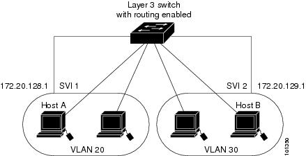
Network devices in different VLANs cannot communicate with one another without a Layer 3 device to route traffic between the VLANs.

VLAN partitions provide hard firewalls for traffic in the VLAN, and each VLAN has its own MAC address table. A VLAN comes into existence when a local port is configured to be associated with the VLAN, when the VLAN Trunking Protocol (VTP) learns of its existence from a neighbor on a trunk, or when a user creates a VLAN. VLANs can be formed with ports across the stack.

To configure VLANs, use the vlan vlan-id global configuration command to enter VLAN configuration mode. The VLAN configurations for normal-range VLANs (VLAN IDs 1 to 1005) are saved in the VLAN database. If VTP is version 1 or 2, to configure extended-range VLANs (VLAN IDs 1006 to 4094), you must first set VTP mode to transparent. Extended-range VLANs created in transparent mode are not added to the VLAN database but are saved in the switch running configuration. With VTP version 3, you can create extended-range VLANs in client or server mode. These VLANs are saved in the VLAN database.

In a switch stack, the VLAN database is downloaded to all switches in a stack, and all switches in the stack build the same VLAN database. The running configuration and the saved configuration are the same for all switches in a stack.

Add ports to a VLAN by using the switchport interface configuration commands:

  • Identify the interface.

  • For a trunk port, set trunk characteristics, and, if desired, define the VLANs to which it can belong.

  • For an access port, set and define the VLAN to which it belongs.

Switch Ports

Switch ports are Layer 2-only interfaces associated with a physical port. Switch ports belong to one or more VLANs. A switch port can be an access port or a trunk port. You can configure a port as an access port or trunk port or let the Dynamic Trunking Protocol (DTP) operate on a per-port basis to set the switchport mode by negotiating with the port on the other end of the link. switch ports are used for managing the physical interface and associated Layer 2 protocols and do not handle routing or bridging.

Configure switch ports by using the switchport interface configuration commands.

Access Ports

An access port belongs to and carries the traffic of only one VLAN (unless it is configured as a voice VLAN port). Traffic is received and sent in native formats with no VLAN tagging. Traffic arriving on an access port is assumed to belong to the VLAN assigned to the port. If an access port receives a tagged packet (Inter-Switch Link [ISL] or IEEE 802.1Q tagged), the packet is dropped, and the source address is not learned.

The types of access ports supported are:

  • Static access ports are manually assigned to a VLAN (or through a RADIUS server for use with IEEE 802.1x.

You can also configure an access port with an attached Cisco IP Phone to use one VLAN for voice traffic and another VLAN for data traffic from a device attached to the phone.

Trunk Ports

A trunk port carries the traffic of multiple VLANs and by default is a member of all VLANs in the VLAN database.

Although by default, a trunk port is a member of every VLAN known to the VTP, you can limit VLAN membership by configuring an allowed list of VLANs for each trunk port. The list of allowed VLANs does not affect any other port but the associated trunk port. By default, all possible VLANs (VLAN ID 1 to 4094) are in the allowed list. A trunk port can become a member of a VLAN only if VTP knows of the VLAN and if the VLAN is in the enabled state. If VTP learns of a new, enabled VLAN and the VLAN is in the allowed list for a trunk port, the trunk port automatically becomes a member of that VLAN and traffic is forwarded to and from the trunk port for that VLAN. If VTP learns of a new, enabled VLAN that is not in the allowed list for a trunk port, the port does not become a member of the VLAN, and no traffic for the VLAN is forwarded to or from the port.

Tunnel Ports

Tunnel ports are used in IEEE 802.1Q tunneling to segregate the traffic of customers in a service-provider network from other customers who are using the same VLAN number. You configure an asymmetric link from a tunnel port on a service-provider edge switch to an IEEE 802.1Q trunk port on the customer switch. Packets entering the tunnel port on the edge switch, already IEEE 802.1Q-tagged with the customer VLANs, are encapsulated with another layer of an IEEE 802.1Q tag (called the metro tag), containing a VLAN ID unique in the service-provider network, for each customer. The double-tagged packets go through the service-provider network keeping the original customer VLANs separate from those of other customers. At the outbound interface, also a tunnel port, the metro tag is removed, and the original VLAN numbers from the customer network are retrieved.

Tunnel ports cannot be trunk ports or access ports and must belong to a VLAN unique to each customer.

Routed Ports

A routed port is a physical port that acts like a port on a router; it does not have to be connected to a router. A routed port is not associated with a particular VLAN, as is an access port. A routed port behaves like a regular router interface, except that it does not support VLAN subinterfaces. Routed ports can be configured with a Layer 3 routing protocol. A routed port is a Layer 3 interface only and does not support Layer 2 protocols, such as DTP and STP.

Configure routed ports by putting the interface into Layer 3 mode with the no switchport interface configuration command. Then assign an IP address to the port, enable routing, and assign routing protocol characteristics by using the ip routing and router protocol global configuration commands.


Note

Entering a no switchport interface configuration command shuts down the interface and then re-enables it, which might generate messages on the device to which the interface is connected. When you put an interface that is in Layer 2 mode into Layer 3 mode, the previous configuration information related to the affected interface might be lost.


The number of routed ports that you can configure is not limited by software. However, the interrelationship between this number and the number of other features being configured might impact CPU performance because of hardware limitations.


Note

The IP Base image supports static routing and the Routing Information Protocol (RIP). For full Layer 3 routing or for fallback bridging, you must enable the IP Services image on the standalone switch, or the active switch.


Switch Virtual Interfaces

A switch virtual interface (SVI) represents a VLAN of switch ports as one interface to the routing or bridging function in the system. You can associate only one SVI with a VLAN. You configure an SVI for a VLAN only to route between VLANs or to provide IP host connectivity to the switch. By default, an SVI is created for the default VLAN (VLAN 1) to permit remote switch administration. Additional SVIs must be explicitly configured.


Note

You cannot delete interface VLAN 1.


SVIs provide IP host connectivity only to the system. SVIs are created the first time that you enter the vlan interface configuration command for a VLAN interface. The VLAN corresponds to the VLAN tag associated with data frames on an ISL or IEEE 802.1Q encapsulated trunk or the VLAN ID configured for an access port. Configure a VLAN interface for each VLAN for which you want to route traffic, and assign it an IP address.

Although the switch stack or switch supports a total of 1005 VLANs and SVIs, the interrelationship between the number of SVIs and routed ports and the number of other features being configured might impact CPU performance because of hardware limitations.

When you create an SVI, it does not become active until it is associated with a physical port.

SVI Autostate Exclude

The line state of an SVI with multiple ports on a VLAN is in the up state when it meets these conditions:

  • The VLAN exists and is active in the VLAN database on the switch

  • The VLAN interface exists and is not administratively down.

  • At least one Layer 2 (access or trunk) port exists, has a link in the up state on this VLAN, and is in the spanning-tree forwarding state on the VLAN.


Note

The protocol link state for VLAN interfaces come up when the first switchport belonging to the corresponding VLAN link comes up and is in STP forwarding state.


The default action, when a VLAN has multiple ports, is that the SVI goes down when all ports in the VLAN go down. You can use the SVI autostate exclude feature to configure a port so that it is not included in the SVI line-state up-or-down calculation. For example, if the only active port on the VLAN is a monitoring port, you might configure autostate exclude on that port so that the VLAN goes down when all other ports go down. When enabled on a port, autostate exclude applies to all VLANs that are enabled on that port.

The VLAN interface is brought up when one Layer 2 port in the VLAN has had time to converge (transition from STP listening-learning state to forwarding state). This prevents features such as routing protocols from using the VLAN interface as if it were fully operational and minimizes other problems, such as routing black holes.

EtherChannel Port Groups

EtherChannel port groups treat multiple switch ports as one switch port. These port groups act as a single logical port for high-bandwidth connections between switches or between switches and servers. An EtherChannel balances the traffic load across the links in the channel. If a link within the EtherChannel fails, traffic previously carried over the failed link changes to the remaining links. You can group multiple trunk ports into one logical trunk port, group multiple access ports into one logical access port, group multiple tunnel ports into one logical tunnel port, or group multiple routed ports into one logical routed port. Most protocols operate over either single ports or aggregated switch ports and do not recognize the physical ports within the port group. Exceptions are the DTP, the Cisco Discovery Protocol (CDP), and the Port Aggregation Protocol (PAgP), which operate only on physical ports.

When you configure an EtherChannel, you create a port-channel logical interface and assign an interface to the EtherChannel. For Layer 3 interfaces, you manually create the logical interface by using the interface port-channel global configuration command. Then you manually assign an interface to the EtherChannel by using the channel-group interface configuration command. For Layer 2 interfaces, use the channel-group interface configuration command to dynamically create the port-channel logical interface. This command binds the physical and logical ports together.

Power over Ethernet Ports

A PoE-capable switch port automatically supplies power to one of these connected devices if the switch senses that there is no power on the circuit:

  • a Cisco pre-standard powered device (such as a Cisco IP Phone or a Cisco Aironet Access Point)

  • an IEEE 802.3af-compliant powered device

A powered device can receive redundant power when it is connected to a PoE switch port and to an AC power source. The device does not receive redundant power when it is only connected to the PoE port.

Using the Switch USB Ports

USB Mini-Type B Console Port

The switch has the following console ports:

  • USB mini-Type B console connection

  • RJ-45 console port

Console output appears on devices connected to both ports, but console input is active on only one port at a time. By default, the USB connector takes precedence over the RJ-45 connector.


Note

Windows PCs require a driver for the USB port. See the hardware installation guide for driver installation instructions.

Use the supplied USB Type A-to-USB mini-Type B cable to connect a PC or other device to the switch. The connected device must include a terminal emulation application. When the switch detects a valid USB connection to a powered-on device that supports host functionality (such as a PC), input from the RJ-45 console is immediately disabled, and input from the USB console is enabled. Removing the USB connection immediately reenables input from the RJ-45 console connection. An LED on the switch shows which console connection is in use.

Console Port Change Logs

At software startup, a log shows whether the USB or the RJ-45 console is active. Each switch in a stack issues this log. Every switch always first displays the RJ-45 media type.

In the sample output, Switch 1 has a connected USB console cable. Because the bootloader did not change to the USB console, the first log from Switch 1 shows the RJ-45 console. A short time later, the console changes and the USB console log appears. Switch 2 and Switch 3 have connected RJ-45 console cables.


switch-stack-1
*Mar  1 00:01:00.171: %USB_CONSOLE-6-MEDIA_RJ45: Console media-type is RJ45.
*Mar  1 00:01:00.431: %USB_CONSOLE-6-MEDIA_USB: Console media-type is USB.

switch-stack-2
*Mar  1 00:01:09.835: %USB_CONSOLE-6-MEDIA_RJ45: Console media-type is RJ45.

switch-stack-3
*Mar  1 00:01:10.523: %USB_CONSOLE-6-MEDIA_RJ45: Console media-type is RJ45.

When the USB cable is removed or the PC de-activates the USB connection, the hardware automatically changes to the RJ-45 console interface:


switch-stack-1
Mar  1 00:20:48.635: %USB_CONSOLE-6-MEDIA_RJ45: Console media-type is RJ45.

You can configure the console type to always be RJ-45, and you can configure an inactivity timeout for the USB connector.

Interface Connections

Devices within a single VLAN can communicate directly through any switch. Ports in different VLANs cannot exchange data without going through a routing device. With a standard Layer 2 switch, ports in different VLANs have to exchange information through a router. By using the switch with routing enabled, when you configure both VLAN 20 and VLAN 30 with an SVI to which an IP address is assigned, packets can be sent from Host A to Host B directly through the switch with no need for an external router.

Figure 1. Connecting VLANs with the Switch

Note

Switches running the LAN Base image support configuring only 16 static routes on SVIs.

Default Ethernet Interface Configuration

To configure Layer 2 parameters, if the interface is in Layer 3 mode, you must enter the switchport interface configuration command without any parameters to put the interface into Layer 2 mode. This shuts down the interface and then re-enables it, which might generate messages on the device to which the interface is connected. When you put an interface that is in Layer 3 mode into Layer 2 mode, the previous configuration information related to the affected interface might be lost, and the interface is returned to its default configuration.

This table shows the Ethernet interface default configuration, including some features that apply only to Layer 2 interfaces.

Table 1. Default Layer 2 Ethernet Interface Configuration

Feature

Default Setting

Operating mode

Layer 2 or switching mode (switchport command).

Allowed VLAN range

VLANs 1– 4094.

Default VLAN (for access ports)

VLAN 1 (Layer 2 interfaces only).

Native VLAN (for IEEE 802.1Q trunks)

VLAN 1 (Layer 2 interfaces only).

VLAN trunking

Switchport mode dynamic auto (supports DTP) (Layer 2 interfaces only).

Port enable state

All ports are enabled.

Port description

None defined.

Speed

Autonegotiate. (Not supported on the 10-Gigabit interfaces.)

Duplex mode

Autonegotiate. (Not supported on the 10-Gigabit interfaces.)

Flow control

Flow control is set to receive: off . It is always off for sent packets.

EtherChannel (PAgP)

Disabled on all Ethernet ports.

Port blocking (unknown multicast and unknown unicast traffic)

Disabled (not blocked) (Layer 2 interfaces only).

Broadcast, multicast, and unicast storm control

Disabled.

Protected port

Disabled (Layer 2 interfaces only).

Port security

Disabled (Layer 2 interfaces only).

Port Fast

Disabled.

Auto-MDIX

Enabled.

Note 

The switch might not support a pre-standard powered device—such as Cisco IP phones and access points that do not fully support IEEE 802.3af—if that powered device is connected to the switch through a crossover cable. This is regardless of whether auto-MIDX is enabled on the switch port.

Power over Ethernet (PoE)

Enabled (auto).

Interface Speed and Duplex Mode

Ethernet interfaces on the switch operate at 10, 100, 1000, or 10,000 Mb/s and in either full- or half-duplex mode. In full-duplex mode, two stations can send and receive traffic at the same time. Normally, 10-Mb/s ports operate in half-duplex mode, which means that stations can either receive or send traffic.

Switch models include Gigabit Ethernet (10/100/1000-Mb/s) ports, 10-Gigabit Ethernet ports, and small form-factor pluggable (SFP) module slots supporting SFP modules.

Speed and Duplex Configuration Guidelines

When configuring an interface speed and duplex mode, note these guidelines:

  • The 10-Gigabit Ethernet ports do not support the speed and duplex features. These ports operate only at 10,000 Mb/s and in full-duplex mode.

  • Do not disable Auto-Negotiation on PoE switches.

  • Gigabit Ethernet (10/100/1000-Mb/s) ports support all speed options and all duplex options (auto, half, and full). However, Gigabit Ethernet ports operating at 1000 Mb/s do not support half-duplex mode.

  • For SFP module ports, the speed and duplex CLI options change depending on the SFP module type:
    • The 1000BASE-x (where -x is -BX, -CWDM, -LX, -SX, and -ZX) SFP module ports support the nonegotiate keyword in the speed interface configuration command. Duplex options are not supported.

    • The 1000BASE-T SFP module ports support the same speed and duplex options as the 10/100/1000-Mb/s ports.

  • If both ends of the line support autonegotiation, we highly recommend the default setting of auto negotiation.

  • If one interface supports autonegotiation and the other end does not, configure duplex and speed on both interfaces; do not use the auto setting on the supported side.

  • When STP is enabled and a port is reconfigured, the switch can take up to 30 seconds to check for loops. The port LED is amber while STP reconfigureAs best practice, we suggest configuring the speed and duplex options on a link to auto or to fixed on both the ends. If one side of the link is configured to auto and the other side is configured to fixed, the link will not be up and this is expected.s.

  • As best practice, we suggest configuring the speed and duplex options on a link to auto or to fixed on both the ends. If one side of the link is configured to auto and the other side is configured to fixed, the link will not be up and this is expected.


Caution

Changing the interface speed and duplex mode configuration might shut down and re-enable the interface during the reconfiguration.


IEEE 802.3x Flow Control

Flow control enables connected Ethernet ports to control traffic rates during congestion by allowing congested nodes to pause link operation at the other end. If one port experiences congestion and cannot receive any more traffic, it notifies the other port by sending a pause frame to stop sending until the condition clears. Upon receipt of a pause frame, the sending device stops sending any data packets, which prevents any loss of data packets during the congestion period.


Note

Flow control is not supported on Catalyst 3850 and Catalyst 3650 Series Switches (CSCul33405).


Note

The switch ports can receive, but not send, pause frames.


You use the flowcontrol interface configuration command to set the interface’s ability to receive pause frames to on , off , or desired . The default state is off .

When set to desired , an interface can operate with an attached device that is required to send flow-control packets or with an attached device that is not required to but can send flow-control packets.

These rules apply to flow control settings on the device:

  • receive on (or desired ): The port cannot send pause frames but can operate with an attached device that is required to or can send pause frames; the port can receive pause frames.

  • receive off : Flow control does not operate in either direction. In case of congestion, no indication is given to the link partner, and no pause frames are sent or received by either device.

Layer 3 Interfaces

The switch supports these types of Layer 3 interfaces:

  • SVIs: You should configure SVIs for any VLANs for which you want to route traffic. SVIs are created when you enter a VLAN ID following the interface vlan global configuration command. To delete an SVI, use the no interface vlan global configuration command. You cannot delete interface VLAN 1.


    Note

    When you create an SVI, it does not become active until it is associated with a physical port.


    When configuring SVIs, you can also configure SVI autostate exclude on a port in the SVI to exclude that port from being included in determining SVI line-state status.

  • Routed ports: Routed ports are physical ports configured to be in Layer 3 mode by using the no switchport interface configuration command.

  • Layer 3 EtherChannel ports: EtherChannel interfaces made up of routed ports.

A Layer 3 switch can have an IP address assigned to each routed port and SVI.

There is no defined limit to the number of SVIs and routed ports that can be configured in a switch or in a switch stack. However, the interrelationship between the number of SVIs and routed ports and the number of other features being configured might have an impact on CPU usage because of hardware limitations. If the switch is using its maximum hardware resources, attempts to create a routed port or SVI have these results:

  • If you try to create a new routed port, the switch generates a message that there are not enough resources to convert the interface to a routed port, and the interface remains as a switchport.

  • If you try to create an extended-range VLAN, an error message is generated, and the extended-range VLAN is rejected.

  • If the switch is notified by VLAN Trunking Protocol (VTP) of a new VLAN, it sends a message that there are not enough hardware resources available and shuts down the VLAN. The output of the show vlan user EXEC command shows the VLAN in a suspended state.

  • If the switch attempts to boot up with a configuration that has more VLANs and routed ports than hardware can support, the VLANs are created, but the routed ports are shut down, and the switch sends a message that this was due to insufficient hardware resources.

All Layer 3 interfaces require an IP address to route traffic. This procedure shows how to configure an interface as a Layer 3 interface and how to assign an IP address to an interface.


Note

If the physical port is in Layer 2 mode (the default), you must enter the no switchport interface configuration command to put the interface into Layer 3 mode. Entering a no switchport command disables and then re-enables the interface, which might generate messages on the device to which the interface is connected. Furthermore, when you put an interface that is in Layer 2 mode into Layer 3 mode, the previous configuration information related to the affected interface might be lost, and the interface is returned to its default configuration


How to Configure Interface Characteristics

Configuring Interfaces

These general instructions apply to all interface configuration processes.

Procedure

  Command or Action Purpose
Step 1

enable

Example:


Switch> enable

Enables privileged EXEC mode. Enter your password if prompted.

Step 2

configure terminal

Example:


Switch# configure terminal

Enters the global configuration mode.

Step 3

interface

Example:


Switch(config)# interface gigabitethernet1/0/1
Switch(config-if)# 

Identifies the interface type, the switch number (only on stacking-capable switches), and the number of the connector.

Note 

You do not need to add a space between the interface type and the interface number. For example, in the preceding line, you can specify either gigabitethernet 1/0/1 , gigabitethernet1/0/1 , gi 1/0/1 , or gi1/0/1 .

Step 4

Follow each interface command with the interface configuration commands that the interface requires.

Defines the protocols and applications that will run on the interface. The commands are collected and applied to the interface when you enter another interface command or enter end to return to privileged EXEC mode.

Step 5

interface range or interface range macro

(Optional) Configures a range of interfaces.
Note 

Interfaces configured in a range must be the same type and must be configured with the same feature options.

Step 6

show interfaces

Displays a list of all interfaces on or configured for the switch. A report is provided for each interface that the device supports or for the specified interface.

Adding a Description for an Interface

Procedure

  Command or Action Purpose
Step 1

enable

Example:


Switch> enable

Enables privileged EXEC mode. Enter your password if prompted.

Step 2

configure terminal

Example:


Switch# configure terminal

Enters global configuration mode.

Step 3

interface interface-id

Example:


Switch(config)# interface gigabitethernet1/0/2

Specifies the interface for which you are adding a description, and enter interface configuration mode.

Step 4

description string

Example:


Switch(config-if)# description Connects to Marketing

Adds a description (up to 240 characters) for an interface.

Step 5

end

Example:


Switch(config-if)# end

Returns to privileged EXEC mode.

Step 6

show interfaces interface-id description

Verifies your entry.

Step 7

copy running-config startup-config

Example:


Switch# copy running-config startup-config 

(Optional) Saves your entries in the configuration file.

Configuring a Range of Interfaces

To configure multiple interfaces with the same configuration parameters, use the interface range global configuration command. When you enter the interface-range configuration mode, all command parameters that you enter are attributed to all interfaces within that range until you exit this mode.

Procedure

  Command or Action Purpose
Step 1

enable

Example:


Switch> enable

Enables privileged EXEC mode. Enter your password if prompted.

Step 2

configure terminal

Example:


Switch# configure terminal

Enters global configuration mode.

Step 3

interface range {port-range | macro macro_name}

Example:


Switch(config)# interface range macro

Specifies the range of interfaces (VLANs or physical ports) to be configured, and enter interface-range configuration mode.

  • You can use the interface range command to configure up to five port ranges or a previously defined macro.

  • The macro variable is explained in the Configuring and Using Interface Range Macros.

  • In a comma-separated port-range , you must enter the interface type for each entry and enter spaces before and after the comma.

  • In a hyphen-separated port-range , you do not need to re-enter the interface type, but you must enter a space before the hyphen.

Note 

Use the normal configuration commands to apply the configuration parameters to all interfaces in the range. Each command is executed as it is entered.

Step 4

end

Example:


Switch(config)# end

Returns to privileged EXEC mode.

Step 5

show interfaces [interface-id]

Example:


Switch# show interfaces

Verifies the configuration of the interfaces in the range.

Step 6

copy running-config startup-config

Example:


Switch# copy running-config startup-config 

(Optional) Saves your entries in the configuration file.

Configuring and Using Interface Range Macros

You can create an interface range macro to automatically select a range of interfaces for configuration. Before you can use the macro keyword in the interface range macro global configuration command string, you must use the define interface-range global configuration command to define the macro.

Procedure

  Command or Action Purpose
Step 1

enable

Example:


Switch> enable

Enables privileged EXEC mode. Enter your password if prompted.

Step 2

configure terminal

Example:


Switch# configure terminal

Enters global configuration mode.

Step 3

define interface-range macro_name interface-range

Example:


Switch(config)# define interface-range enet_list gigabitethernet1/0/1 - 2

Defines the interface-range macro, and save it in NVRAM.

  • The macro_name is a 32-character maximum character string.

  • A macro can contain up to five comma-separated interface ranges.

  • Each interface-range must consist of the same port type.

Note 

Before you can use the macro keyword in the interface range macro global configuration command string, you must use the define interface-range global configuration command to define the macro.

Step 4

interface range macro macro_name

Example:


Switch(config)# interface range macro enet_list

Selects the interface range to be configured using the values saved in the interface-range macro called macro_name .

You can now use the normal configuration commands to apply the configuration to all interfaces in the defined macro.

Step 5

end

Example:


Switch(config)# end

Returns to privileged EXEC mode.

Step 6

show running-config | include define

Example:


Switch# show running-config | include define

Shows the defined interface range macro configuration.

Step 7

copy running-config startup-config

Example:


Switch# copy running-config startup-config 

(Optional) Saves your entries in the configuration file.

Configuring Ethernet Interfaces

Setting the Interface Speed and Duplex Parameters

Procedure
  Command or Action Purpose
Step 1

enable

Example:

Switch> enable

Enables privileged EXEC mode. Enter your password if prompted.

Step 2

configure terminal

Example:

Switch# configure terminal

Enters global configuration mode.

Step 3

interface interface-id

Example:

Switch(config)# interface gigabitethernet1/0/3

Specifies the physical interface to be configured, and enter interface configuration mode.

Step 4

speed {10 | 100 | 1000 | 2500 | 5000 | 10000 | auto [10 | 100 | 1000 | 2500 | 5000 | 10000] | nonegotiate}

Example:

Switch(config-if)# speed 10

Enter the appropriate speed parameter for the interface:

  • Enter 10 , 100 , 1000 2500 , 5000 , or 10000 to set a specific speed for the interface.

  • Enter auto to enable the interface to autonegotiate speed with the connected device. If you specify a speed and also set the auto keyword, the port autonegotiates only at the specified speeds.

  • The nonegotiate keyword is available only for SFP module ports. SFP module ports operate only at 1000 Mb/s but can be configured to not negotiate if connected to a device that does not support autonegotiation.

Step 5

duplex {auto | full | half}

Example:

Switch(config-if)# duplex half

This command is not available on a 10-Gigabit Ethernet interface.

Enter the duplex parameter for the interface.

Enable half-duplex mode (for interfaces operating only at 10 or 100 Mb/s). You cannot configure half-duplex mode for interfaces operating at 1000 Mb/s.

You can configure the duplex setting when the speed is set to auto .

Step 6

end

Example:

Switch(config-if)# end

Returns to privileged EXEC mode.

Step 7

show interfaces interface-id

Example:

Switch# show interfaces gigabitethernet1/0/3

Displays the interface speed and duplex mode configuration.

Step 8

copy running-config startup-config

Example:

Switch# copy running-config startup-config

(Optional) Saves your entries in the configuration file.

Step 9

copy running-config startup-config

Example:

Switch# copy running-config startup-config 

(Optional) Saves your entries in the configuration file.

Configuring IEEE 802.3x Flow Control

Procedure

  Command or Action Purpose
Step 1

configure terminal

Example:


Switch# configure terminal

Enters global configuration mode

Step 2

interface interface-id

Example:


Switch(config)# interface gigabitethernet1/0/1

Specifies the physical interface to be configured, and enter interface configuration mode.

Step 3

flowcontrol {receive} {on | off | desired}

Example:


Switch(config-if)# flowcontrol receive on

Configures the flow control mode for the port.

Step 4

end

Example:


Switch(config-if)# end

Returns to privileged EXEC mode.

Step 5

show interfaces interface-id

Example:


Switch# show interfaces gigabitethernet1/0/1

Verifies the interface flow control settings.

Step 6

copy running-config startup-config

Example:


Switch# copy running-config startup-config 

(Optional) Saves your entries in the configuration file.

Configuring Layer 3 Interfaces

Procedure

  Command or Action Purpose
Step 1

enable

Example:


Switch> enable

Enables privileged EXEC mode. Enter your password if prompted.

Step 2

configure terminal

Example:


Switch# configure terminal

Enters global configuration mode.

Step 3

interface {gigabitethernet interface-id} | {vlan vlan-id} | {port-channel port-channel-number}

Example:


Switch(config)# interface gigabitethernet1/0/2

Specifies the interface to be configured as a Layer 3 interface, and enter interface configuration mode.

Step 4

no switchport

Example:


Switch(config-if)# no switchport

For physical ports only, enters Layer 3 mode.

Step 5

ip address ip_address subnet_mask

Example:


Switch(config-if)# ip address 192.20.135.21 255.255.255.0

Configures the IP address and IP subnet.

Step 6

no shutdown

Example:


Switch(config-if)# no shutdown

Enables the interface.

Step 7

end

Example:


Switch(config-if)# end

Returns to privileged EXEC mode.

Step 8

show interfaces [interface-id]

Verifies the configuration.

Step 9

copy running-config startup-config

Example:


Switch# copy running-config startup-config 

(Optional) Saves your entries in the configuration file.

Configuring Logical Layer 3 GRE Tunnel Interfaces

Before you begin

Generic Routing Encapsulation (GRE) is a tunneling protocol used to encapsulate network layer protocols inside virtual point-to-point links. A GRE tunnel only provides encapsulation and not encryption.


Attention

Beginning in Cisco IOS XE Release 3.7.2E, GRE tunnels are supported on the hardware on Cisco Catalyst switches. When GRE is configured without tunnel options, packets are hardware-switched. When GRE is configured with tunnel options (such as key, checksum, etc.), packets are switched in the software. A maximum of 10 GRE tunnels are supported.


Note

Other features like Access Control Lists (ACL) and Quality of Service (QoS) are not supported for the GRE tunnels.


To configure a GRE tunnel, perform this task:

Procedure

  Command or Action Purpose
Step 1

interface tunnel number

Example:

Switch(config)#interface tunnel 2

Enables tunneling on the interface.

Step 2

ip addressip_addresssubnet_mask

Example:

Switch(config)#ip address 100.1.1.1 255.255.255.0

Configures the IP address and IP subnet.

Step 3

tunnel source{ip_address | type_number}

Example:

Switch(config)#tunnel source 10.10.10.1

Configures the tunnel source.

Step 4

tunnel destination{host_name | ip_address}

Example:

Switch(config)#tunnel destination 10.10.10.2

Configures the tunnel destination.

Step 5

tunnel mode gre ip

Example:

Switch(config)#tunnel mode gre ip

Configures the tunnel mode.

Step 6

end

Example:

Switch(config)#end

Exist configuration mode.

Configuring SVI Autostate Exclude

Procedure

  Command or Action Purpose
Step 1

enable

Example:


Switch> enable

Enables privileged EXEC mode. Enter your password if prompted.

Step 2

configure terminal

Example:


Switch# configure terminal

Enters global configuration mode.

Step 3

interface interface-id

Example:


Switch(config)# interface gigabitethernet1/0/2

Specifies a Layer 2 interface (physical port or port channel), and enter interface configuration mode.

Step 4

switchport autostate exclude

Example:


Switch(config-if)# switchport autostate exclude

Excludes the access or trunk port when defining the status of an SVI line state (up or down)

Step 5

end

Example:


Switch(config-if)# end

Returns to privileged EXEC mode.

Step 6

show running config interface interface-id

(Optional) Shows the running configuration.

Verifies the configuration.

Step 7

copy running-config startup-config

Example:


Switch# copy running-config startup-config 

(Optional) Saves your entries in the configuration file.

Shutting Down and Restarting the Interface

Shutting down an interface disables all functions on the specified interface and marks the interface as unavailable on all monitoring command displays. This information is communicated to other network servers through all dynamic routing protocols. The interface is not mentioned in any routing updates.

Procedure

  Command or Action Purpose
Step 1

enable

Example:


Switch> enable

Enables privileged EXEC mode. Enter your password if prompted.

Step 2

configure terminal

Example:


Switch# configure terminal

Enters global configuration mode.

Step 3

interface {vlan vlan-id} | { gigabitethernetinterface-id} | {port-channel port-channel-number}

Example:


Switch(config)# interface gigabitethernet1/0/2

Selects the interface to be configured.

Step 4

shutdown

Example:


Switch(config-if)# shutdown

Shuts down an interface.

Step 5

no shutdown

Example:


Switch(config-if)# no shutdown

Restarts an interface.

Step 6

end

Example:


Switch(config-if)# end

Returns to privileged EXEC mode.

Step 7

show running-config

Example:


Switch# show running-config 

Verifies your entries.

Configuring the Console Media Type

Follow these steps to set the console media type to RJ-45. If you configure the console as RJ-45, USB console operation is disabled, and input comes only through the RJ-45 connector.

This configuration applies to all switches in a stack.

Procedure

  Command or Action Purpose
Step 1

enable

Example:


Switch> enable

Enables privileged EXEC mode. Enter your password if prompted.

Step 2

configure terminal

Example:


Switch# configure terminal

Enters the global configuration mode.

Step 3

line console 0

Example:


Switch(config)# line console 0

Configures the console and enters line configuration mode.

Step 4

media-type rj45

Example:


Switch(config-line)# media-type rj45

Configures the console media type to be only RJ-45 port. If you do not enter this command and both types are connected, the USB port is used by default.

Step 5

end

Example:


Switch(config)# end

Returns to privileged EXEC mode.

Step 6

copy running-config startup-config

Example:


Switch# copy running-config startup-config 

(Optional) Saves your entries in the configuration file.

Configuring the USB Inactivity Timeout

The configurable inactivity timeout reactivates the RJ-45 console port if the USB console port is activated but no input activity occurs on it for a specified time period. When the USB console port is deactivated due to a timeout, you can restore its operation by disconnecting and reconnecting the USB cable.


Note

The configured inactivity timeout applies to all switches in a stack. However, a timeout on one switch does not cause a timeout on other switches in the stack.


Procedure

  Command or Action Purpose
Step 1

enable

Example:


Switch> enable

Enables privileged EXEC mode. Enter your password if prompted.

Step 2

configure terminal

Example:


Switch# configure terminal

Enters the global configuration mode.

Step 3

line console 0

Example:


Switch(config)# line console 0

Configures the console and enters line configuration mode.

Step 4

usb-inactivity-timeout timeout-minutes

Example:


Switch(config-line)# usb-inactivity-timeout 30

Specify an inactivity timeout for the console port. The range is 1 to 240 minutes. The default is to have no timeout configured.

Step 5

copy running-config startup-config

Example:


Switch# copy running-config startup-config 

(Optional) Saves your entries in the configuration file.

Monitoring Interface Characteristics

Monitoring Interface Status

Commands entered at the privileged EXEC prompt display information about the interface, including the versions of the software and the hardware, the configuration, and statistics about the interfaces.

Table 2. Show Commands for Interfaces

Command

Purpose

show interfaces interface-id status [err-disabled]

Displays interface status or a list of interfaces in the error-disabled state.

show interfaces [interface-id] switchport

Displays administrative and operational status of switching (nonrouting) ports. You can use this command to find out if a port is in routing or in switching mode.

show interfaces [interface-id] description

Displays the description configured on an interface or all interfaces and the interface status.

show ip interface [interface-id]

Displays the usability status of all interfaces configured for IP routing or the specified interface.

show interface [interface-id] stats

Displays the input and output packets by the switching path for the interface.

show interfaces interface-id

(Optional) Displays speed and duplex on the interface.

show interfaces transceiver dom-supported-list

(Optional) Displays Digital Optical Monitoring (DOM) status on the connect SFP modules.

show interfaces transceiver properties

(Optional) Displays temperature, voltage, or amount of current on the interface.

show interfaces [interface-id] [{transceiver properties | detail}] module number]

Displays physical and operational status about an SFP module.

show running-config interface [interface-id]

Displays the running configuration in RAM for the interface.

show version

Displays the hardware configuration, software version, the names and sources of configuration files, and the boot images.

show controllers ethernet-controller interface-id phy

Displays the operational state of the auto-MDIX feature on the interface.

Clearing and Resetting Interfaces and Counters

Table 3. Clear Commands for Interfaces

Command

Purpose

clear counters [interface-id]

Clears interface counters.

clear interface interface-id

Resets the hardware logic on an interface.

clear line [number | console 0 | vty number]

Resets the hardware logic on an asynchronous serial line.


Note

The clear counters privileged EXEC command does not clear counters retrieved by using Simple Network Management Protocol (SNMP), but only those seen with the show interface privileged EXEC command.


Configuration Examples for Interface Characteristics

Adding a Description to an Interface: Example


Switch# configure terminal
Enter configuration commands, one per line. End with CNTRL/Z.
Switch(config)# interface gigabitethernet1/0/2
Switch(config-if)# description Connects to Marketing
Switch(config-if)# end
Switch# show interfaces gigabitethernet1/0/2 description
Interface Status         Protocol Description
Gi1/0/2   admin down     down     Connects to Marketing

Configuring a Range of Interfaces: Examples

This example shows how to use the interface range global configuration command to set the speed to 100 Mb/s on ports 1 to 4 on switch 1:


Switch# configure terminal
Switch(config)# interface range gigabitethernet1/0/1 - 4 
Switch(config-if-range)# speed 100

This example shows how to use a comma to add different interface type strings to the range to enable Gigabit Ethernet ports 1 to 3 and 10-Gigabit Ethernet ports 1 and 2 to receive flow-control pause frames:


Switch# configure terminal
Switch(config)# interface range gigabitethernet1/0/1 - 3 , tengigabitethernet1/0/1 - 2
Switch(config-if-range)# flowcontrol receive on

If you enter multiple configuration commands while you are in interface-range mode, each command is executed as it is entered. The commands are not batched and executed after you exit interface-range mode. If you exit interface-range configuration mode while the commands are being executed, some commands might not be executed on all interfaces in the range. Wait until the command prompt reappears before exiting interface-range configuration mode.

Configuring and Using Interface Range Macros: Examples

This example shows how to define an interface-range named enet_list to include ports 1 and 2 on switch 1 and to verify the macro configuration:


Switch# configure terminal
Switch(config)# define interface-range enet_list gigabitethernet1/0/1 - 2
Switch(config)# end
Switch# show running-config | include define 
define interface-range enet_list GigabitEthernet1/0/1 - 2

This example shows how to create a multiple-interface macro named macro1:


Switch# configure terminal
Switch(config)# define interface-range macro1 gigabitethernet1/0/1 - 2, gigabitethernet1/0/5 - 7, tengigabitethernet1/0/1 -2
Switch(config)# end

This example shows how to enter interface-range configuration mode for the interface-range macro enet_list:


Switch# configure terminal
Switch(config)# interface range macro enet_list
Switch(config-if-range)# 

This example shows how to delete the interface-range macro enet_list and to verify that it was deleted.


Switch# configure terminal
Switch(config)# no define interface-range enet_list 
Switch(config)# end
Switch# show run | include define
Switch# 

Setting Interface Speed and Duplex Mode: Example

This example shows how to set the interface speed to 100 Mb/s and the duplex mode to half on a 10/100/1000 Mb/s port:


Switch# configure terminal
Switch(config)# interface gigabitethernet1/0/3
Switch(config-if)# speed 10
Switch(config-if)# duplex half

This example shows how to set the interface speed to 100 Mb/s on a 10/100/1000 Mb/s port:


Switch# configure terminal
Switch(config)# interface gigabitethernet1/0/2
Switch(config-if)# speed 100

Configuring Layer 3 Interfaces: Example


Switch# configure terminal
Enter configuration commands, one per line.  End with CNTL/Z.
Switch(config)# interface gigabitethernet1/0/2
Switch(config-if)# no switchport
Switch(config-if)# ip address 192.20.135.21 255.255.255.0
Switch(config-if)# no shutdown

Configuring the Console Media Type: Example

This example disables the USB console media type and enables the RJ-45 console media type.


Switch# configure terminal
Switch(config)# line console 0
Switch(config-line)# media-type rj45

This configuration terminates any active USB console media type in the stack. A log shows that this termination has occurred. This example shows that the console on switch 1 reverted to RJ-45.


*Mar  1 00:25:36.860: %USB_CONSOLE-6-CONFIG_DISABLE: Console media-type USB disabled by system configuration, media-type reverted to RJ45.

At this point no switches in the stack allow a USB console to have input. A log entry shows when a console cable is attached. If a USB console cable is connected to switch 2, it is prevented from providing input.


*Mar  1 00:34:27.498: %USB_CONSOLE-6-CONFIG_DISALLOW: Console media-type USB is disallowed by system configuration, media-type remains RJ45. (switch-stk-2)

This example reverses the previous configuration and immediately activates any USB console that is connected.


Switch# configure terminal
Switch(config)# line console 0
Switch(config-line)# no media-type rj45

Configuring the USB Inactivity Timeout: Example

This example configures the inactivity timeout to 30 minutes:


Switch# configure terminal
Switch(config)# line console 0
Switch(config-line)# usb-inactivity-timeout 30

To disable the configuration, use these commands:


Switch# configure terminal
Switch(config)# line console 0
Switch(config-line)# no usb-inactivity-timeout

If there is no (input) activity on a USB console port for the configured number of minutes, the inactivity timeout setting applies to the RJ-45 port, and a log shows this occurrence:


*Mar  1 00:47:25.625: %USB_CONSOLE-6-INACTIVITY_DISABLE: Console media-type USB disabled due to inactivity, media-type reverted to RJ45.

At this point, the only way to reactivate the USB console port is to disconnect and reconnect the cable.

When the USB cable on the switch has been disconnected and reconnected, a log similar to this appears:


*Mar  1 00:48:28.640: %USB_CONSOLE-6-MEDIA_USB: Console media-type is USB.

Additional References for the Interface Characteristics Feature

Error Message Decoder

Description Link

To help you research and resolve system error messages in this release, use the Error Message Decoder tool.

https://www.cisco.com/cgi-bin/Support/Errordecoder/index.cgi

Standards and RFCs

Standard/RFC Title
None --

MIBs

MIB MIBs Link

All supported MIBs for this release.

To locate and download MIBs for selected platforms, Cisco IOS releases, and feature sets, use Cisco MIB Locator found at the following URL:

http://www.cisco.com/go/mibs

Technical Assistance

Description Link

The Cisco Support website provides extensive online resources, including documentation and tools for troubleshooting and resolving technical issues with Cisco products and technologies.

To receive security and technical information about your products, you can subscribe to various services, such as the Product Alert Tool (accessed from Field Notices), the Cisco Technical Services Newsletter, and Really Simple Syndication (RSS) Feeds.

Access to most tools on the Cisco Support website requires a Cisco.com user ID and password.

http://www.cisco.com/support

Feature History and Information for Configuring Interface Characteristics

Release

Modification

Cisco IOS XE 3.2SECisco IOS XE 3.3SECisco IOS XE 3.3SE

This feature was introduced.