- Index
- Preface
- Product Overview
- Command-Line Interfaces
- Configuring the Switch for the First Time
- Configuring Interfaces
- Checking Port Status and Connectivity
- Configuring Supervisor Engine Redundancy on the Catalyst 4507R and Catalyst 4510R Switches
- Understanding and Configuring VLANs
- Configuring Dynamic VLAN Membership
- Configuring Layer 2 Ethernet Interfaces
- Configuring Role-Based Macros
- Understanding and Configuring STP
- Configuring STP Features
- Understanding and Configuring Multiple Spanning Trees
- Understanding and Configuring EtherChannel
- Configuring IGMP Snooping and Filtering
- Configuring 802.1Q and Layer 2 Protocol Tunneling
- Understanding and Configuring CDP
- Configuring UDLD
- Configuring Unidirectional Ethernet
- Configuring Layer 3 Interfaces
- Configuring Cisco Express Forwarding
- Understanding and Configuring IP Multicast
- Configuring Policy-Based Routing
- Understanding and Configuring VTP
- Configuring VRF-lite
- Configuring QoS
- Configuring Voice Interfaces
- Configuring 802.1x Port-Based Authentication
- Configuring Port Security
- Configuring DHCP Snooping and IP Source Guard
- Understanding and Configuring Dynamic ARP Inspection
- Configuring Network Security with ACLs
- Configuring Private VLANs
- Port Unicast and Multicast Flood Blocking
- Configuring Port-Based Traffic Control
- Environmental Monitoring and Power Management
- Configuring SPAN and RSPAN
- Configuring NetFlow Statistics Collection
- Acronyms
Configuring Layer 3 Interfaces
This chapter describes the Layer 3 interfaces on a Catalyst 4500 series switch. It also provides guidelines, procedures, and configuration examples.
This chapter includes the following major sections:
•![]() Overview of Layer 3 Interfaces
Overview of Layer 3 Interfaces
•![]() Configuring Logical Layer 3 VLAN Interfaces
Configuring Logical Layer 3 VLAN Interfaces
•![]() Configuring Physical Layer 3 Interfaces
Configuring Physical Layer 3 Interfaces

Note ![]() For complete syntax and usage information for the switch commands used in this chapter, look at the Cisco Catalyst 4500 Series Switch Command Reference and related publications at this location:
For complete syntax and usage information for the switch commands used in this chapter, look at the Cisco Catalyst 4500 Series Switch Command Reference and related publications at this location:
http://www.cisco.com/en/US/products/hw/switches/ps4324/index.html
If the command is not found in the Catalyst 4500 Command Reference, it is located in the larger Cisco IOS library. Refer to the Catalyst 4500 Series Switch Cisco IOS Command Reference and related publications at this location:
http://www.cisco.com/en/US/products/ps6350/index.html
Overview of Layer 3 Interfaces
This section contains the following subsections:
•![]() Logical Layer 3 VLAN Interfaces
Logical Layer 3 VLAN Interfaces
The Catalyst 4500 series switch supports Layer 3 interfaces with the Cisco IOS IP and IP routing protocols. Layer 3, the network layer, is primarily responsible for the routing of data in packets across logical internetwork paths.
Layer 2, the data link layer, contains the protocols that control the physical layer (Layer 1) and how data is framed before being transmitted on the medium. The Layer 2 function of filtering and forwarding data in frames between two segments on a LAN is known as bridging.
The Catalyst 4500 series switch supports two types of Layer 3 interfaces. The logical Layer 3 VLAN interfaces integrate the functions of routing and bridging. The physical Layer 3 interfaces allow the Catalyst 4500 series switch to be configured like a traditional router.
Logical Layer 3 VLAN Interfaces
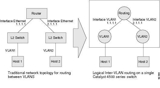
The logical Layer 3 VLAN interfaces provide logical routing interfaces to VLANs on Layer 2 switches. A traditional network requires a physical interface from a router to a switch to perform inter-VLAN routing. The Catalyst 4500 series switch supports inter-VLAN routing by integrating the routing and bridging functions on a single Catalyst 4500 series switch.
Figure 20-1 shows how the routing and bridging functions in the three physical devices of the traditional network are performed logically on one Catalyst 4500 series switch.
Figure 20-1 Logical Layer 3 VLAN Interfaces for the Catalyst 4500 Series Switch
Physical Layer 3 Interfaces
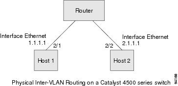
The physical Layer 3 interfaces support capabilities equivalent to a traditional router. These Layer 3 interfaces provide hosts with physical routing interfaces to a Catalyst 4500 series switch.
Figure 20-2 shows how the Catalyst 4500 series switch functions as a traditional router.
Figure 20-2 Physical Layer 3 Interfaces for the Catalyst 4500 Series Switch
Configuration Guidelines
A Catalyst 4500 series switch supports AppleTalk routing and IPX routing. For AppleTalk routing and IPX routing information, refer to "Configuring AppleTalk" and "Configuring Novell IPX" in the Cisco IOS AppleTalk and Novell IPX Configuration Guide at the following URL:
http://www.cisco.com/univercd/cc/td/doc/product/software/ios122/122cgcr/atipx_c/index.htm
A Catalyst 4500 series switch does not support subinterfaces or the encapsulation keyword on Layer 3 Fast Ethernet or Gigabit Ethernet interfaces.
Configuring Logical Layer 3 VLAN Interfaces
Note ![]() Before you can configure logical Layer 3 VLAN interfaces, you must create and configure the VLANs on the switch, assign VLAN membership to the Layer 2 interfaces, enable IP routing if IP routing is disabled, and specify an IP routing protocol.
Before you can configure logical Layer 3 VLAN interfaces, you must create and configure the VLANs on the switch, assign VLAN membership to the Layer 2 interfaces, enable IP routing if IP routing is disabled, and specify an IP routing protocol.
To configure logical Layer 3 VLAN interfaces, perform this task:
This example shows how to configure the logical Layer 3 VLAN interface vlan 2 and assign an IP address:
Switch> enable
Switch# config term
Enter configuration commands, one per line. End with CNTL/Z.
Switch(config)# vlan 2
Switch(config)# interface vlan 2
Switch(config-if)# ip address 10.1.1.1 255.255.255.248
Switch(config-if)# no shutdown
Switch(config-if)# end
This example uses the show interfaces command to display the interface IP address configuration and status of Layer 3 VLAN interface vlan 2:
Switch# show interfaces vlan 2
Vlan2 is up, line protocol is down
Hardware is Ethernet SVI, address is 00D.588F.B604 (bia 00D.588F.B604)
Internet address is 172.20.52.106/29
MTU 1500 bytes, BW 1000000 Kbit, DLY 10 usec,
reliability 255/255, txload 1/255, rxload 1/255
Encapsulation ARPA, loopback not set
ARP type: ARPA, ARP Timeout 04:00:00
Last input never, output never, output hang never
Last clearing of "show interface" counters never
Input queue: 0/75/0/0 (size/max/drops/flushes); Total output drops: 0
Queueing strategy: fifo
Output queue: 0/40 (size/max)
5 minute input rate 0 bits/sec, 0 packets/sec
5 minute output rate 0 bits/sec, 0 packets/sec
0 packets input, 0 bytes, 0 no buffer
Received 0 broadcasts, 0 runts, 0 giants, 0 throttles
0 input errors, 0 CRC, 0 frame, 0 overrun, 0 ignored
0 packets output, 0 bytes, 0 underruns
0 output errors, 0 interface resets
0 output buffer failures, 0 output buffers swapped out
Switch#
This example uses the show running-config command to display the interface IP address configuration of Layer 3 VLAN interface vlan 2:
Switch# show running-config
Building configuration...
Current configuration : !
interface Vlan2
ip address 10.1.1.1 255.255.255.248
!
ip classless
no ip http server
!
!
line con 0
line aux 0
line vty 0 4
!
end
Configuring Physical Layer 3 Interfaces
Note ![]() Before you can configure physical Layer 3 interfaces, you must enable IP routing if IP routing is disabled, and specify an IP routing protocol.
Before you can configure physical Layer 3 interfaces, you must enable IP routing if IP routing is disabled, and specify an IP routing protocol.
To configure physical Layer 3 interfaces, perform this task:
This example shows how to configure an IP address on Fast Ethernet interface 2/1:
Switch# configure terminal
Enter configuration commands, one per line. End with CNTL/Z.
Switch(config)# ip routing
Switch(config)# interface fastethernet 2/1
Switch(config-if)# no switchport
Switch(config-if)# ip address 10.1.1.1 255.255.255.248
Switch(config-if)# no shutdown
Switch(config-if)# end
Switch#
This example uses the show running-config command to display the interface IP address configuration of Fast Ethernet interface 2/1:
Switch# show running-config
Building configuration...
!
interface FastEthernet2/1
no switchport
ip address 10.1.1.1 255.255.255.248
!
...
ip classless
no ip http server
!
!
line con 0
line aux 0
line vty 0 4
!
end
 Feedback